Télécharger Imprimer la page

Publicité

Les langues disponibles

Les langues disponibles

Liens rapides

1
Information GOLD maxi
Art. Nr. / Art. no. / Art. n° 10440
th
4. Auflage / 4
Edition / 4. Edition 02 14
B.B.10.0062

Publicité

loading

Sommaire des Matières pour Lenz Digital Plus GOLD maxi

  • Page 1 Information GOLD maxi Art. Nr. / Art. no. / Art. n° 10440 4. Auflage / 4 Edition / 4. Edition 02 14 B.B.10.0062...
  • Page 2 Information GOLD maxi ext.K. GOLD maxi...
  • Page 3 Technische Daten / Technical Data / Données techniques: Maximale Maximum continuous Charge totale Dauerbelastbar- current-carrying maximale keit des gesamten capacity of total autorisée du Decoders decoder décodeur Motorausgang Motor output Sortie moteur 3 / 5 A Dauer/Spitze Continuous / maximum Continu/En pointe power Funktions-...
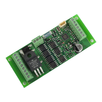
  • Page 4 Information GOLD maxi Motor ext.K. Abb. 1: Anschluss des GOLD maxi The connection of the GOLD maxi Raccordement du décodeur GOLD maxi...
  • Page 5 Abb. 2: Anschluss des GOLD maxi The connection of the GOLD maxi Raccordement du décodeur GOLD maxi...
  • Page 6 Information GOLD maxi charge Abb. 3: USP – Anschluss / USP connection / Raccordement USP S.U.S.I. – Schnittstelle / S.U.S.I. interface / Interface S.U.S.I.
  • Page 7 ext.K. Abb. 4: Externer Reed-Kontakt / external reed contact / contact Reed externe...
  • Page 8 Information GOLD maxi Nicht geeignet für Kinder unter 14 Jahren wegen verschluckbarer Kleinteile. Bei unsachgemäßem Gebrauch besteht Verletzungsgefahr durch funktionsbedingte Kanten und Spitzen! Nur für trockene Räume. Irrtum sowie Änderung aufgrund des technischen Fortschrittes, der Produktpflege oder anderer Herstellungsmethoden bleiben vorbehalten. Jede Haftung für Schäden und Folgeschäden durch nicht bestimmungsgemäßen Gebrauch, Nichtbeachtung dieser Gebrauchsanweisung, Betrieb mit nicht für Modellbahnen zugelassenen, umgebauten oder schadhaften Transformatoren bzw.
  • Page 9 Les appareils numériques sont non indiqués pour les enfants en dessous de 14 ans en raison des petites pièces susceptibles d'être avalées. En cas d'utilisation incorrecte existe un danger de blessures dues à des arêtes vives ! Les appareils sont uniquement utilisables dans des locaux secs.
  • Page 10 Information GOLD maxi Wichtige Sicherheitshinweise: Digital plus Lokdecoder dürfen ausschließlich mit dem Digital plus by Lenz System oder einer anderen handelsüblichen Digitalsteuerungen mit NMRA-Konformitäts-Siegel verwendet werden. Fragen Sie im Zweifelsfall beim Lieferanten des Systems nach. Die in den technischen Daten angegebenen Belastbarkeiten dürfen nicht überschritten werden. Sie müssen sicherstellen, dass diese maximale Belastbarkeit nicht überschritten wird.
  • Page 11 Einbau des GOLD maxi (Abb.1, S.4) Notieren Sie sich, welcher Motoranschluss mit den rechten und welcher mit den linken Radschleifern verbunden ist. Dies erspart Ihnen beim Anschluss des Decoders Versuche, welcher der beiden Motorausgänge M1 und M2 des Decoders mit welchem Motoranschluss verbunden werden muss, um die richtige Fahrtrichtung einzustellen.
  • Page 12 Information GOLD maxi  Funktionsausgang FA an die in Fahrtrichtung vorne liegende Stirnbeleuchtung  Funktionsausgang FB an die in Fahrtrichtung hinten liegende Stirnbeleuchtung Besteht eine Verbindung zwischen Glühbirnen und Chassis, so ist der Anschluss der Stirnbeleuchtung damit abgeschlossen. Sind die Glühbirnchen nicht elektrisch mit dem Chassis der Lokomotive verbunden (wir nennen diese dann "potentialfrei"), so verbinden Sie den anderen Pol der Lampenmit dem Anschluss U+ des GOLD maxi (welche der beiden U+-Anschlüsse Sie verwenden ist gleichgültig.
  • Page 13 Im Folgenden geben wir Ihnen einen kurzen Überblick über die Eigenschaften des GOLD maxi und deren Einstellung. Ausführliche Informationen zu den Eigenschaften und deren Einstellungen finden Sie im "Handbuch Plus-Decoder" welches Sie von der Website der Lenz Elektronik GmbH herunterladen können: www.lenz-elektronik.de/pdf/download.php 4.1 Leistung und Schutzeinrichtungen Der Motorausgang ist bis 3A dauernd belastbar, und dies ohne spezielle Montage auf Kühlflächen!
  • Page 14 Information GOLD maxi ohne Knickstellen zu gewährleisten. Unabhängig davon ist es außerdem möglich, eine individuelle Geschwindigkeitskennlinie zu programmieren. Der Decoder besitzt weiterhin einen so genannten EMK-Teiler, der eine Anpassung des Decoders an verschiedene Motortypen ermöglicht. Je nach verwendetem Motor kann es vorkommen, dass eine digital gesteuerte Lokomotive im Vergleich zum konventionellen Betrieb keine ausreichende Höchstgeschwindigkeit erreicht.
  • Page 15 Sie aktivieren Sie den konstanten Bremsweg bei Fahrstufe 0 durch Setzen des Bit 8(7) in der CV51 Ausführliche Informationen zur Einstellung des Bremsweges finden Sie im „Handbuch Plus-Decoder“, welches Sie von der Website der Lenz Elektronik GmbH herunterladen können: www.lenz-elektronik.de/pdf/download.php Weitere wichtige Hinweise: ...
  • Page 16 Information GOLD maxi 4.6 Rangiergang Der Rangiergang halbiert die Geschwindigkeit. Eine besonders feinfühlige Regelung zum Rangieren wird so möglich. Mit der Funktion 3 (Werkseinstellung, kann in CV58 geändert werden) schalten Sie den Rangiergang ein und aus. Wenn der Rangiergang eingeschaltet ist, ist der konstante Bremsweg ausgeschaltet.
  • Page 17 Sie in der Tabelle der unterstützen CVs weiter unten. 4.11 Die S.U.S.I. Schnittstelle In Kooperation der Firmen DIETZ und LENZ enstand das Konzept einer Sound- und Funktionsschnittstelle für Lokdecoder. Sinn dieser Schnittstelle ist es, Sound- und andere Funktionsmodule auf besonders einfache Weise an einen Lokdecoder anzuschließen.
  • Page 18 (PoM)" als auch über das "Programmieren auf dem Programmiergleis" vorgenommen werden. Bei ® Einsatz von Digital plus by Lenz Systemen können Sie mit PoM die CVs 1 bis 999 verändern, beim "Programmieren auf dem Programmiergleis" erreichen Sie zurzeit die CVs 1 bis 256. Für die S.U.S.I.
  • Page 19 Soll die Ziel-CV nur gelesen werden, so wird nach dem Einschreiben des Ziels in CV126 die Transport CV127 ausgelesen. Da in eine CV nur Werte bis 255 eingegeben werden können, die CVs für SUSI aber bei 897 beginnen, ist die Zeiger CV mit dem Offset 800 "vorgeladen". Sie müssen nur noch die Differenz zur gewünschten Ziel-CV eingeben, beispielsweise für die Ziel-CV897 also die Zahl 97.
  • Page 20 Information GOLD maxi 4.13 Kupplungssteuerung Der Decoder ermöglicht an allen Funktionsausgängen eine komfortable Steuerung von fernbedienbaren Kupplungen. Der gewählte Ausgang stellt für eine einstellbare Zeit die volle Leistung (Kickdauer), nach Ablauf dieser Zeit eine reduzierte Leistung zur Verfügung. Wie weit die Leistung reduziert wird, ist ebenfalls einstellbar.
  • Page 21 eingestellten Bremsweg bis zum Stillstand ab. Wenn die Lok wieder anfahren soll, so stellen zuerst die Geschwindigkeit auf Fahrstufe 0 und können danach die Lok wieder anfahren. Nothalt: Überfährt die Lok während des Abbremsens einen zweiten Magneten (Kontakt wird erneut geschlossen), so hält sie sofort, also ohne Verzögerung (oder den eingestellten Bremsweg abzufahren) an.
  • Page 22 Information GOLD maxi Decoder dauerhaft, also auch beim Abschalten der Betriebsspannung, "aufgehoben". In der (amerikanischen) Normung werden die Speicher als "Configuration Variable", kurz: "CV" bezeichnet. Das Einschreiben/Auslesen der Werte erfolgt elektronisch, die Lokomotive muss also nach Einbau des Decoders nicht mehr geöffnet werden. Zur Programmierung des Decoders können folgende Digital plus Geräte eingesetzt werden: Zentrale LZ100 / LZV100 (mit einem Handregler oder dem Interface);...
  • Page 23 1-127 Basis – Lokadresse ® Dies ist die Nummer, mit der Sie die Loks im Digital plus by Lenz ® System aufrufen. Für die Verwendung mit Digital plus by Lenz Geräten ist nur der Bereich 1-99 zugelassen. Beim Schreiben...
  • Page 24 Information GOLD maxi RailCom Konfiguration 7 (dec) 1 (0) Kanal 1 freigegeben für Adress-Broadcast 2 (1) Kanal 2 freigegeben für Daten und Acknowledge 6 (dec) Einstellungen 1 1 (0) Richtung der Lok normal: Lok fährt nach vorne, wenn der Pfeil auf dem Handregler nach oben zeigt.
  • Page 25 6 (5) Decoder verwendet Basisadresse (aus CV1) Decoder verwendet erweiterte Adresse (aus CV17 u. CV18) 7-8(6-7) nicht verwendet Fehleranzeige 0 (dec) 1 (0) Lampen- Kurzschluss 2 (1) Übertemperatur 3 (2) Motor Kurzschluss Werte- Funktionszuordnung (Mapping) für Funktionsausgänge: Werks- bereich Um eine Funktion des Digitalsystems einem Funktionsausgang einstellung zuzuordnen sucht man den Schnittpunkt der Zeile der gewünsch- –...
  • Page 26 Information GOLD maxi 0-255 Funktion 8 0-255 Funktion 9 0-255 Funktion 10 0-255 Funktion 11 0-255 Funktion 12 0-255 F1 rückwärts Motor Konfiguration 4(dec) 1-4 (0-3) Auswahl des Motortyps 0-5, Eingabe als Dezimalzahl 6 (5) EMK-Teiler nicht aktiv EMK-Teiler aktiv 7 (6) Regelung eingeschaltet Regelung ausgeschaltet...
  • Page 27 0-255 Bremsweg bei aktiviertem konstanten Bremsweg 0-255 Langsamfahrt bei ABC 0-255 Aufenthaltsdauer bei Pendelbetrieb, 1 bis 256 Sekunden 0-255 stellt die Helligkeit an den F-Ausgängen A und C ein, 255=max 0-255 stellt die Helligkeit an den F-Ausgängen B und D ein, 255=max Funktionszuordnung (Mapping): Jedes Bit der CV steht für eine Funktion des Digitalsystems: Bit 1(0) für Funktion 1, Bit 2(1) für Funktion 2 und so weiter bis...
  • Page 28 Information GOLD maxi kein Effekt kein Effekt Blinken im Gleichtakt zu Blinken F-Ausgang C Flackern Typ 1 (ruhig) Blinken im Gegentakt zu Dimmen mit Wert aus F-Ausgang C CV55 Flackern Typ 2 (unruhiger) Flackern Typ 3 (hektisch) Dimmen mit Wert aus CV56 Blinkfrequenz für F-Ausgänge C und D: für eine bestimmte Frequenz (f) ergibt sich der Wert für CV63 aus...
  • Page 29 0-255 Transport CV für SUSI Servicenummer (aktuelle Nummer bitte auslesen) Funktionszuordnung F13 – F28 zu den Ausgängen Ausgang: 0-255 Funktion 13 0-255 Funktion 14 0-255 Funktion 15 0-255 Funktion 16 0-255 Funktion 17 0-255 Funktion 18 0-255 Funktion 19 0-255 Funktion 20 0-255 Funktion 21...
  • Page 30 Information GOLD maxi 0-16 Funktionszuordnung Kupplungssteuerung vorwärts Funktionsausgang: 0-16 Funktionszuordnung Kupplungssteuerung rückwärts Funktionsausgang: 0-255 „Kickdauer“: Einstellbar in Vielfachen von 0,016 Sekunden. Die Werkseinstellung enspricht 30x0,016 Sekunden = 0,48 Sekunden 0-255 Verfahren der Lok beim Entkuppeln "vom Zug weg". Einstellbar in Vielfachen von 0,016 Sekunden.
  • Page 32 Information GOLD maxi Important safety instructions Digital plus locomotive decoders are to be used only with Lenz Digital plus or other standard digital control systems with an NMRA-conformance seal. If in doubt, ask the system supplier. Please note that the maximum current-carrying capacity of the outputs may not be exceeded as this...
  • Page 33 Installing the GOLD decoder via cable connection (Abb. 1, p.4) Please note which motor connection is connected to the right rail pickups and which to the left. If you do this, you will not have to try out which of the two motor outputs M1 and M2 of the decoder needs to be connected to which motor connection to set the desired direction of travel.
  • Page 34 The following contains a short survey of the features of the GOLD maxi as well as information on how to set them. You can find detailed information on the features and their settings in the “Manual Plus Decoders” that you can download from the Lenz Elektronik GmbH website www.lenz- elektronik.de...
  • Page 35 4.1 Capacity and Protection equipment The motor output has a current-carrying capacity of up to 3A even without special installation on cooling surfaces! The short-term maximum current-carrying capacity is 5A. The function outputs have current-carrying capacities of 1000mA each. The decoder is protected against overloading, short circuits and overheating. In case of a fault, the corresponding bit is set in CV30 which will state the type of fault which has occured.
  • Page 36 Information GOLD maxi 4.3 Running notches The decoder can be operated in the 14/27 or the 28/128 running-notches mode. This setting is made in CV29. 4.4 Disabling of delay Use function 4 (ex-works setting, can be altered in CV60) to disable the starting and braking delay as well as the constant braking distance during operation.
  • Page 37 You can find detailed information on setting the braking distance in the “Manual Plus Decoders” that download from Lenz Elektronik GmbH website www.lenz- elektronik.de/pdf/download.php Important advice: The length of the covered braking distance is set in CV52. The braking distance differs depending on the value set in this CV.
  • Page 38 Information GOLD maxi signal. The decoder reacts to this. Combined with the constant braking distance, precise on-the- spot stopping in front of red signals is not a problem. Of course, passage in the opposite direction is also possible. The signal indication "slow approach/caution" does not pose a problem; the respective speed can be set in CV53.
  • Page 39 allocations to functions F1 to F8 in CV61 (for function outputs A and B) and CV64 (for function outputs C and D). The effects available are shown in the table of the supported CVs further below. 4.11 The S.U.S.I. interface The sound and function interface concept for locomotive decoders was devised in 2002 in cooperation with the company DIETZ.
  • Page 40 The settings of the S.U.S.I. module can be carried out both through "Programming in operational ® mode (PoM)" or "Programming on the programming track". When using Digital plus by Lenz systems, you can change CVs 1 to 999 with PoM, while "Programming on the programming track" is currently used for CVs 1 to 256.
  • Page 41 Example 2: You wish to read out the present value of CV902 of the S.U.S.I. module: Enter 902-800=102 in the indicator CV126. Read out the transport device CV127. The value of CV902 of the connected module is displayed. 4.12 USP – Uninterruptable Signal Processing In combination with the optional energy storage, the intelligent USP circuit ensures that your locomotive can run even over dirty track sections or dead frogs.
  • Page 42: Signal Stop

    Information GOLD maxi Signal stop and push-pull control with an external reed contact The GOLD maxi has a connection for an external reed contact. The reed contact is installed at the bottom of the locomotive. You can let your locomotive stop in front of a signal or operate in push- pull operation with the help of a magnet installed in the track.
  • Page 43: Resetting The Decoder

    is ignored. The locomotive will continue until it reaches the magnet at the end of the push-pull section. There, the locomotive will brake again, wait for the set stopping time to elapse, change ist direction of travel, and continue in this direction – and the game starts all over again. Programming the decoder The locomotive address, acceleration and deceleration delay, and all other features of the locomotive decoder can be changed as often as desired by reprogramming the decoder.
  • Page 44 Ex-works Meaning setting 1-127 Basic locomotive address. This number is used to call up ® locomotives in the Digital plus by Lenz system. The use of range 1-99 is recommended for operation with ® Digital plus by Lenz devices. When writing this CV, CV19 (multiple traction address) is automatically deleted in the decoder and Bit 6 (use of extended address) is deleted in CV29.
  • Page 45 Settings 1 6 (dec) 1 (0) Direction of travel normal: locomotive drives forward if the arrow on the manual control points up. interchanged: locomotive drives forward if the arrow on the manual control points down. 2 (1) Running-notches mode: Operation with 14 or 27 running notches. This setting is chosen for digital systems which do not support the 28 running-notches mode.
  • Page 46 Information GOLD maxi Fault display 0 (dec) 1 (0) Light short-circuit 2 (1) Overheating 3 (2) Motor short-circuit Range of Function mapping for function outputs: In order to allocate a Ex-works values function of the digital system to a function output, look for the setting section where the row of the desired function meets the column of –...
  • Page 47 0-255 Function 12 0-255 F1 backward Motor configuration 4 (dec) 1-4 (0-3) Select motor type 0-5, enter as decimal number 6 (5) EMF switch inactive EMF switch active 7 (6) Control switched on Control switched off 8 (7) High-frequency motor control (approx. 23 kHz) Low-frequency motor control (approx.
  • Page 48 Information GOLD maxi 0-255 Sets brightness at function outputs B and D, 255=max Function mapping: Each bit of the CV stands for a function of the digital system: Bit 1(0) for function 1, Bit 2(1) for function 2 and so on up to Bit 8(7) for function 8.
  • Page 49 output C Dimming with value Flickering type 2 (less smooth) from CV55 Flickering type 3 (excitedly) Dimming with value from CV56 Flashing frequency for function outputs C and D: default approx. 1 sec, f = 1 / ( 0.03 * (1 + CV63)) Function mapping: lighting effect at function outputs C and D 0-255 Values for characteristic speed line, default = ex-works speed line...
  • Page 50 Information GOLD maxi 0-255 Function 17 0-255 Function 18 0-255 Function 19 0-255 Function 20 0-255 Function 21 0-255 Function 22 0-255 Function 23 0-255 Function 24 0-255 Function 25 0-255 Function 26 0-255 Function 27 0-255 Function 28 0-16 Function allocation coupling control forward Function output: 0-16...
  • Page 51 of 0,016 seconds. Factory setting is 80x 0,016s = 1,28s Control with external contact 1(0) Signal stop activated with external contact 2(1) Push-pull operation activated with external contact...
  • Page 52 Information GOLD maxi Remarques importantes Tout décodeur Digital plus est exclusivement destiné à être utilisé avec Lenz DIGITAL plus ou un autre système de pilotage digital du commerce portant le sigle de compatibilité NMRA. En cas de doute, demandez des explications au revendeur du système.
  • Page 53 Montage du décodeur GOLD avec câbles (fig. 1, page 4) Veuillez noter la correspondance entre les bornes du moteur et les patins de prise de courant droits et gauches. Ceci vous évitera de rechercher, lors du raccordement du décodeur, dans quel ordre vous devrez souder les deux sorties M1 et M2 du décodeur aux bornes de sortie du moteur pour que la locomotive roule dans le bon sens.
  • Page 54 Information GOLD maxi S'il existe une liaison entre les ampoules et le châssis, la connexion des feux de signalisation est alors réalisée. Si les ampoules ne sont pas reliées électriquement au châssis de la locomotive (donc, si elles sont au potentiel zéro), reliez le second pôle des ampoules à la borne U+ du décodeur GOLD Maxi (peu importe laquelle des deux bornes U+).
  • Page 55: Puissance Et Sécurité

    Vous trouverez des informations plus détaillées dans le "Manuel du décodeur" que vous pouvez obtenir auprès de votre détaillant spécialisé ou télécharger sur le site Internet de la firme Lenz Elektronik GmbH : www.lenz-elektronik.com. 4.1 Puissance et sécurité La sortie moteur peut être chargée jusqu'à 1 A en régime continu et ceci sans le recours spécial à...
  • Page 56 Information GOLD maxi Les vitesses minimale (CV 2), maximale (CV 5) et moyenne (CV 6) peuvent être réglées, obligeant ainsi le décodeur à adapter la courbe caractéristique de vitesse de façon dynamique afin de garantir une course régulière et douce du moteur exempte d'à-coups. Indépendamment de cela, il est en outre possible de programmer une courbe caractéristique de vitesse individuelle.
  • Page 57 (7) dans la CV 51. Vous trouverez dans le "Manuel Décodeurs-Plus" des informations détaillées à propos du paramétrage de la distance de freinage. Ce manuel est téléchargeable sur le site Internet de Lenz Elektronik GmbH : www.lenz-elektronik.de/pdf/download.php. 4.5 Mode de marche "manœuvre"...
  • Page 58: Abc (Automatic Braking Control) = Arrêt Automatique Devant Un Signal Avec Marche Au Ralenti

    Information GOLD maxi 4.6 ABC (Automatic Braking Control) = Arrêt automatique devant un signal avec marche au ralenti L'utilisation des modules ABC permet de réaliser très simplement l'arrêt devant les signaux. En fonction de l'aspect que présente un signal déterminé, le module ABC qui lui est associé génère une asymétrie dans le courant digital appliqué...
  • Page 59 D. Pour connaître les effets disponibles, consultez le tableau des CV supportées (ci-après). 4.10 L'interface S.U.S.I. Les firmes DIETZ et LENZ ont annoncé, l'année dernière, qu'elles avaient conjointement mis au point un nouveau concept d'interface pour décodeur de locomotive. Le but de cette nouvelle interface est de pouvoir connecter au décodeur de locomotive, de manière particulièrement simple,...
  • Page 60 "Programmation pendant la marche (PoM)" que par la méthode "Programmation sur la voie de ® programmation". Avec le système Digital plus by Lenz , on peut modifier les CV 1 à 999 au moyen de la PoM, et les CV 1 à 256 avec la "Programmation sur la voie de programmation". Le domaine de CV allant de 897 à...
  • Page 61 transfert. Si la CV-cible ne peut être que lue, la CV 127-transfert est lue après inscription de la cible dans la CV 126. Comme on ne peut encoder que des valeurs allant jusqu'à 255 dans une CV et que les CV inhérentes aux modules S.U.S.I.
  • Page 62: Télécommande Des Attelages

    Information GOLD maxi 4.12 Télécommande des attelages Via les sorties de fonction le décodeur permet une télécommande confortable des attelages. Pendant un temps limité réglable, la sortie sélectionnée dispose d'une pleine puissance. Une fois ce temps écoulé, la puissance est de nouveau réduite. La valeur de la réduction de puissance est également réglable.
  • Page 63 de se remettre en marche, il faut positionner le régulateur sur le cran 0 avant de lui conférer une vitesse. Arrêt d'urgence : Si la locomotive franchit un second aimant au cours de son ralentissement (le contact se ferme de nouveau), elle s'arrête aussitôt sans aucun freinage progressif (ou sans tenir compte de la distance de freinage encodée).
  • Page 64: Réinstallation Des Paramètres D'usine Dans Le Décodeur

    Information GOLD maxi propriétés sont "conservées" de manière permanente au sein du décodeur, même après avoir débranché le courant d'alimentation. Dans les normes (américaines), les emplacements mémoriels sont désignés "Configuration Variable", en abrégé "CV". L'encodage et la lecture des valeurs mémorisées se font électroniquement de sorte que la locomotive ne devra plus jamais être ouverte une fois le décodeur installé.
  • Page 65 1-127 Adresse de base de locomotive. Ceci est le numéro avec lequel vous appelez la locomotive dans ® le système Digital plus by Lenz . Pour une utilisation avec les ® appareils Digital plus by Lenz , seules les adresses 1-99 sont permises.
  • Page 66 Information GOLD maxi Configuration RailCom 7 (déc.) 1 (0) Canal 1 autorisé pour "Adress-Broadcast" 2 (1) Canal 2 autorisé pour données et admission instruction Réglages de niveau 1 6 (déc.) 1 (0) Sens de marche de la locomotive : Normal : la locomotive roule en avant lorsque la flèche sur l'écran du régulateur pointe vers le haut.
  • Page 67 5 (4) Courbe caractéristique de vitesse encodée en usine Courbe caractériser. de vitesse définie par l'utilisateur 6 (5) Le décodeur utilise l'adresse de base (en CV 1). Le décodeur utilise l'adresse étendue (en CV 17 et 18). 7-8 (6-7) Non utilisé. Annonce d'erreur 0 (déc.) 1 (0)
  • Page 68 Information GOLD maxi Sortie de fonction : 0-255 Fonction 5 0-255 Fonction 6 0-255 Fonction 7 0-255 Fonction 8 0-255 Fonction 9 0-255 Fonction 10 0-255 Fonction 11 0-255 Fonction 12 0-255 Fonction 1 arrière Configuration moteur 4 (déc.) 1-4 (0-3) Choix du type de moteur 0-5, entrée en nombre décimal.
  • Page 69 4 (3) Exploitation en navette sans arrêt intermédiaire activée 5 (4) Exploitation en navette avec arrêt intermédiaire activée 6 (5) Arrêter avec le courant continu indépendamment de la polarité (n'est pris en compte que si le bit 3 est éteint dans la CV29) 7 (6) Bit non utilisés...
  • Page 70 Information GOLD maxi 0-255 Désactivation de la temporisation (touche F4 encodée en usine) 0-255 Effets lumineux aux sorties de fonction A et B. Le chiffre des unités vaut pour la sortie A et le chiffre des dizaines vaut pour la sortie B : Aucun effet Marslight (gyrophare lent)
  • Page 71 encodée en CV 56 Fréquence de clignotement pour les sorties de fonction C et D : par défaut, env. 1 seconde. f = 1 / ( 0,03 * (1 + CV 63)) Attribution des fonctions aux sorties de fonction C et D pour la commande des effets lumineux 0-255 Valeurs pour la courbe caractéristique de vitesse ;...
  • Page 72 Information GOLD maxi Attribution des touches de fonction F13 – F28 (mapping) aux sorties de fonction : Sortie de fonction 0-255 Fonction 13 0-255 Fonction 14 0-255 Fonction 15 0-255 Fonction 16 0-255 Fonction 17 0-255 Fonction 18 0-255 Fonction 19 0-255 Fonction 20 0-255...
  • Page 73 0-16 Attribution d'une touche de fonction à la télécommande des attelages en marche avant. Sortie de fonction : 0-16 Attribution d'une touche de fonction à la télécommande des attelages en marche arrière. Sortie de fonction : 0-255 La durée de pleine puissance est réglable sur une série de valeurs multiples de 0,016 secondes.
  • Page 74 Information GOLD maxi...
  • Page 76 Information GOLD maxi Vogelsang 14 D - 35398 Gießen Hotline: 06403 900 133 Fax: 06403 900 155 http://www.lenz-elektronik.de info@digital-plus.de Diese Betriebsanleitung bitte für späteren Gebrauch aufbewahren! Keep this operation manual for future reference! Conservez ce manuel pour une utilisation ultérieure !

Ce manuel est également adapté pour:

10440