Table des Matières
Publicité
Les langues disponibles
Les langues disponibles
Liens rapides
Best.-Nr. 4459
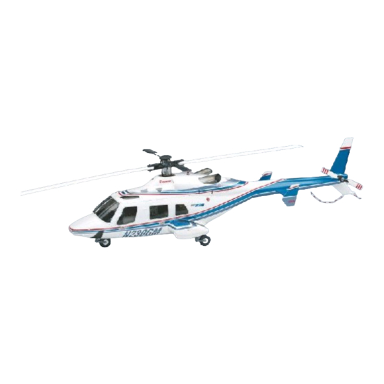
Bell 230
Rumpfbausatz zu UNI-Mechanik 2000,
Uni-Expert-Mechanik oder Starlet 50
Warnung!
Der mit diesem Bausatz erstellte RC-Hubschrauber ist kein Spielzeug! Er ist ein kompli-
ziertes Fluggerät, das durch unsachgemässen Umgang schwere Sach- und Personen-
schäden verursachen kann.
Sie allein sind für die korrekte Fertigstellung und einen gefahrlosen Betrieb verantwort-
lich! Bitte beachten Sie unbedingt die beiliegenden Blätter SHW3 und SHW7 mit Sicher-
heitshinweisen, sie sind Bestandteil dieser Anleitung.
GRAUPNER GmbH & Co. KG D-73230 KIRCHHEIM/TECK GERMANY
Änderungen, Irrtümer und Druckfehler vorbehalten
ID# 31014
6/04
Publicité
Chapitres
Table des Matières

Manuels Connexes pour GRAUPNER heim Bell 230


Sommaire des Matières pour GRAUPNER heim Bell 230
- Page 1 Sie allein sind für die korrekte Fertigstellung und einen gefahrlosen Betrieb verantwort- lich! Bitte beachten Sie unbedingt die beiliegenden Blätter SHW3 und SHW7 mit Sicher- heitshinweisen, sie sind Bestandteil dieser Anleitung. GRAUPNER GmbH & Co. KG D-73230 KIRCHHEIM/TECK GERMANY Änderungen, Irrtümer und Druckfehler vorbehalten ID# 31014...
- Page 2 Bell 230 Vorwort Das Modell 230 ist ein 9-sitziger Mehrzweckhubschrauber der Fa. Bell Helicopter TEXTRON und wurde als Nachfolgemuster des bekannten Typs 222 entwickelt. Angetrieben von zwei Allison 250 C-30 G/2 - Turbinen mit jeweils 700 SHP Startleistung besitzt dieser Hub-schrauber bei einem maximalen Abfluggewicht von 3,8t eine Dienstgipfelhöhe von 4500m und erreicht eine maximale Reisegeschwindigkeit von 228km/h.
- Page 3 Bell 230 Warnhinweise • • • • Das aus diesem Bausatz betriebsfertig aufgebaute Modell ist kein harmloses Spiel- zeug! Es kann durch mangelhaften Aufbau und/oder unsachgemässe oder fahrlässige Handhabung beim Betrieb zu schweren Sach- und Personenschäden führen. • • • • Ein Hubschrauber hat zwei im Betrieb schnell drehende Rotoren mit einer hohen Drehenergie.
- Page 4 Fa. Graupner zur Leistung von Schadenersatz, gleich aus welchem Rechtsgrund, be- grenzt auf den Rechnungswert der an dem schadenstiftenden Ereignis unmittelbar betei- ligten Warenmenge der Fa. Graupner. Dies gilt nicht, soweit die Fa. Graupner nach zwin- genden gesetzlichen Vorschriften wegen Vorsatz oder grober Fahrlässigkeit unbe-...
-
Page 5: Table Des Matières
Bell 230 Inhaltsübersicht • Vorwort ..........• Warnhinweise ......... • Zubehör, zusätzlich benötigte Artikel ......• 1. Montage ..........1.1 Vorarbeiten und Hinweise • ......1.2 Zugangsöffnung für den Mechanikeinbau herstellen • ..1.3 Einziehfahrwerk, Hauptfahrwerk ......• 1.4 Bugfahrwerk ........S.11 •... - Page 6 Minimum. Grobes Schleifpapier, z. B. Körnung 100, Best.-Nr. 1068.1 zum Aufrauhen der Klebestellen und zum Aus- und Nacharbeiten der GFK-Zelle. Fernlenkanlage (siehe Handbuch Mechanik bzw. Graupner-Hauptkatalog) Erforderlich ist eine mit speziellen Hubschrauberoptionen ausgestattete Fernlenkanlage oder eine Microcomputer-Fernlenkanlage wie z. B. mc-14, mc-15, mc-19, mc-22 oder mc-24 Servos (nur hochwertige Ausführungen verwenden), z.B.
-
Page 7: Montage
Bell 230 1. Montage 1.1 Vorarbeiten und Hinweise Die in Klammern () gesetzten Ziffern bezeichnen die Positionen gemäss Stückliste am Schluss. Die Rümpfe werden in Handarbeit gefertigt und weisen innen unter Umständen Differenzen auf (Mittelnaht). Durch die Seitenfenster sind wichtige Teile der Mechanik gut zugänglich. Vor dem endgültigen Einbau von Teilen sind diese zuerst einzupassen und ohne Klebstoff provisorisch auszurichten. -
Page 8: Einziehfahrwerk, Hauptfahrwerk
Bell 230 Die beiden Holzlaschen (A25) gemäss Abbildung auf den Quersteg aufkleben und den Steg in seiner ursprünglichen Position am Rumpf wieder exakt ausrichten; dann Laschen (A25) an der markierten Stelle mit dem Rumpf zusammen verbohren (Ø 1,5 mm). Bohrungen in den Laschen auf 2,2mm Ø... - Page 9 Bell 230 Im Flugbetrieb werden die Fahrwerksgabeln bei am Boden stehendem Modell stets an den An- schlägen anliegen; die Feder dient lediglich dazu, nach dem Abheben die Räder in die zum Einfahren erforderlichen Positionen zu bringen. 1.3.3. Einbau des Hauptfahrwerks Zunächst werden die Aussparungen in der Unterseite der Flügelstummel anhand der Markierun- gen herausgeschnitten.
- Page 10 Bell 230 Die beiden äusseren Spanten A15 und A16 werden nun in ihre Position - bündig mit den Aussenkanten der Fahrwerkausschnitte - gebracht und provisorisch leicht mit Klebstoff ange- heftet. Dann werden die Hauptfahrwerksbeine mit zuvor eingedrückten Wellen F32 eingesetzt, danach die inneren Spanten A17 bzw A18, wobei der Stift F3 am Hebel F24 jeweils in die Nut im Fahrwerksbein eingreifen muss.
-
Page 11: Bugfahrwerk
Bell 230 1.4 Bugfahrwerk 1.4.1 Spantengerüst erstellen In die Mechanikauflage A11 werden an den markierten Stellen zwei Bohrungen mit 3mm Ø an- gebracht. Das Spantengerüst für das Bugrad wird dann aus den Teilen (A1)...(A6) und (A11) gemäss Abbildung zusammengesetzt, sorgfältig ausgerichtet und verklebt. Der Lagerbock für den Betätigungshebel (F24) aus den Teilen (A5) und (A6) muss innen am linken Längsspant (A1) angebracht werden. - Page 12 Bell 230 Das Bugfahrwerk wird auf der Welle (F28) gelagert; sie läuft in den kleinen Buchsen (F27), die von innen in (A1) und (A2) fluchtend eingeklebt werden. Da das Fahrwerk schmaler ist als die Lagerung, werden links und rechts die beiden Distanzbuchsen (F41) eingesetzt. Fahrwerkbein einbauen und dabei den Stift (F3) in (F23) einhängen.
-
Page 13: Einbau Der Mechanik
Bell 230 Ende des Schlitzes anliegt oder ob ein geringer Abstand verbleibt: Wichtig ist die sichere Ver- riegelung in ausgefahrenem Zustand, und daraufhin sind Gestänge und Hebel sorgfältig zu ju- stieren. Wenn die endgültige Position der Hebel (F24) gefunden ist, jeweils eine der zwei Stiftschrauben in den beiden Stellringen (F26) gut festziehen, die jeweils andere herausdrehen und durch die Gewindebohrung mit Bohrer 2,4mm Ø... - Page 14 Bell 230 1.5.3 Endgültige Verklebung der Mechanikbefestigung Wenn alles passt, Blechschrauben in den Teilen (A13/A14) wieder herausdrehen und die unte- ren Befestigungsschrauben der Mechanik so weit lösen, dass Klebstoff (UHU plus endfest 300) zwischen die Klötzchen (A23) und die Auflagebrettchen sowie an die Messingröhrchen hinten am Rumpfboden gegeben werden kann;...
- Page 15 Kugelköpfen beträgt ca. 40 mm. Die Servos werden über ein V-Kabel mit der Empfangsanlage verbunden, so dass die Einzieh- fahrwerksfunktion justiert werden kann: Bei Graupner-Fernsteuerungen soll der Servoweg beid- seitig 100% betragen, die Betätigung erfolgt mit einem Kippschalter. Zunächst Gestänge und Servohebelposition bei ausgefahrenem Fahrwerk so justieren, dass die Fahrwerksbeine sicher mechanisch verriegelt werden, ohne dass das Servo dabei blockiert wird.
-
Page 16: Kufenlandegestell
Bell 230 1.6 Kufenlandegestell Das Modell kann, wie auch das Vorbild, ausser mit funktionsfähigem Einziehfahrwerk auch mit einem Kufenlandegestell gebaut werden. Der Aufbau der Version mit Kufenlandegestell wird entsprechend der beschriebenen Version mit Einziehfahrwerk vorgenommen, mit folgenden Abweichungen: • Alle Fahrwerksteile entfallen, es werden keine Fahrwerksausschnitte in der Rumpfunterseite angebracht. -
Page 17: Heckrotor
Bell 230 1.7 Heckrotor 1.7.1 Montage des Heckrotors Aus den zwei miteinander verleimten Teilen (A9) wird der Heckrotorspant gefertigt. Spant zu- nächst provisorisch ins Rumpfheck einpassen. Heckrotor am Spant mit drei Blechschrauben 2,9x13 befestigen, dann die Einheit in das Rumpfheck einschieben. Das Heck besitzt einen umlaufenden Falz zur Befestigung der Heckkappe (B3). - Page 18 Bell 230 1.7.2.2 Einbau der Lagerleiste Die Nutleiste (B6) auf eine Länge von 500mm kürzen (Reststück aufbewahren!). Das Führungs- rohr (B8) auf 540mm ablängen und vorn und hinten je einen ca. 3 mm breiten Ring aus Kraft- stoffschlauch (bei der Mechanik) aufdrücken, dann das Führungsrohr auf die Welle (B9) auf- schieben.
-
Page 19: Leitwerke
Bell 230 1.7.2.3 Endgültiger Einbau des Heckrotorantriebes In den beiden vorangegangenen Abschnitten wurde der Heckantrieb provisorisch eingepasst und zusammengebaut, so dass die Teile jetzt passen müssen und deren Lage bekannt ist. Die Heckantriebswelle (B9) aus dem Führungsrohr (B8) herausziehen, im Bereich des Füh- rungsrohres leicht einölen und wieder hineinschieben. -
Page 20: Hecksporn
Bell 230 Die beiden Höhenflossenhälften werden durch zwei eingeleimte Verbindungsdrähte am Rumpf gehalten. Die Bohrpositionen am Rumpf sind anhand der eingeprägten Markierungen anzubrin- gen. Überprüfen, dass Heckrotorantrieb oder Heckrotorsteuerung nicht durch die Verbindungs- drähte behindert werden. Die Flossen werden nach dem Lackieren auf die durch den Rumpf gesteckten Drähte aufgefädelt und mit den Drähten und dem Rumpf mit Epoxikleber verklebt. -
Page 21: Fertigstellen Von Oberer Rumpfabdeckung Und Heckkappe
Bell 230 Schalldämpferkonsole (4450.149) als Lagerung verwendet werden, wodurch der Schalldämpfer fest an der Mechanik ausgerichtet ist, was Ein- und Ausbau der Mechanik zu Wartungsarbeiten wesentlich erleichtert. Die Konsole muss den Erfordernissen entsprechend eingebaut werden, so dass das mit einem Silikonschlauch überzogene und verlängerte Endrohr des Schalldämp- fers durch eine möglichst kleine Öffnung im Rumpf nach aussen führt. -
Page 22: Schwerpunkt
Bell 230 Der Fenstersatz enthält auch die beiden Auspuffattrappen aus rauchfarben getöntem Material. Sie werden bis auf einen ca. 5mm breiten Rand ausgeschnitten und an den Enden geöffnet. Ein sehr realistischer Eindruck ergibt sich, wenn die Abgasrohre von innen mit Airbrush oder Sprühdose lackiert werden, und zwar zuerst ganz dünn kupferfarben (nicht deckend), dann sil- berfarben und zum Schluss matt schwarz. -
Page 23: Einstellarbeiten
Die nachfolgenden Abschnitte sind in gleicher oder ähnlicher Form auch in den Montagehand- büchern der Mechaniken enthalten, werden hier jedoch noch einmal angefügt, falls eine ältere Graupner/Heim Uni-Expert-Mechanik zum Einsatz kommt, die mit den ursprünglichen Bauplä- nen geliefert wurde. 2.1 Einstellen der zyklischen Steuerung Die Grundeinstellung von Roll-und Nicksteuerung sollte bereits korrekt sein, wenn die Gestänge... -
Page 24: Weitere Einstellungen
Bell 230 2.4 Weitere Einstellungen Wenn alle Gestängeverbindungen gemäss den vorausgegangenen Bauabschnitten hergestellt worden sind, können die nachfolgenden Einstellungen am Sender vorgenommen werden: 1. Servolaufrichtungen Den Drehsinn aller Servos entsprechend den Angaben in der Anleitung einstellen. Beson- dere Aufmerksamkeit dabei auf das Gasservo richten! 2. - Page 25 Einstellung der Kreiselwirkung zu einem Aufschwingen (Pendelbewegungen des Heckauslegers) des Modells kommt. Besondere Hinweise für den Einsatz der Piezo-Kreiselsysteme Graupner/JR „PIEZO 450...5000“ in Verbindung mit einer Computer-Fernsteuerung (z.B. mc-12...mc-24) Die fortschrittliche Konstruktion dieser Kreiselsysteme macht ein vom zuvor Beschriebenen abweichendes Vorgehen gemäss dem nachfolgenden Schema erforderlich:...
-
Page 26: Endkontrolle Vor Dem Erstflug
Bell 230 3. Endkontrolle vor dem Erstflug Wenn der Zusammenbau des Modells abgeschlossen ist, sollten die folgenden Überprüfungen vor dem Erstflug durchgeführt werden: • Gehen Sie dieses Handbuch noch einmal durch und stellen Sie sicher, dass alle Aufbau- schritte korrekt durchgeführt wurden. •... -
Page 27: Einstellungen Beim Erstflug, Spurlauf-Einstellung
Bell 230 6. Einstellungen beim Erstflug 6.1 Spurlaufeinstellung „Spurlaufeinstellung“ beschreibt einen Einstellvorgang, bei dem die Einstellwinkel der Haupt- rotorblätter auf genau die gleichen Werte gebracht werden, so dass die Blätter im Betrieb exakt in der selben Ebene laufen. Ein nicht korrekter Spurlauf, bei dem die Blätter in unterschiedlichen Ebenen laufen, hat starke Vibrationen des Modells im Fluge zur Folge. -
Page 28: Motor - Einstellhinweise
Bell 230 6.2 Motor - Einstellhinweise Für die Motoreinstellung vor allem die dem Motor beiliegende Anleitung beachten! Die korrekte Abstimmung von Pitch und Gas im Schwebeflug ist von entscheidender Bedeutung für Flugverhalten und -leistung des Modells. Ein zu hoher Anstellwinkel der Rotorblätter beispielsweise führt dazu, dass der Motor nicht die vorgesehene Drehzahl erreicht und irrtümlich als zu schwach eingeschätzt wird, zumal er dabei sehr heiss wird und so zusätzlich an Leistung verliert. -
Page 29: Allgemeine Vorsichtsmassnahmen
Bell 230 7. Allgemeine Vorsichtsmassnahmen • Eine Haftpflichtversicherung abschliessen. • Nach Möglichkeit Mitglied in einem Modellflugverein und -verband werden. 7.1 Auf dem Flugfeld: • Mit Modellen keine Zuschauer überfliegen. • Modelle nicht in der Nähe von Gebäuden oder Fahrzeugen betreiben. •... - Page 30 Bell 230 8.3 Drehmomentausgleich Der drehende Rotor erzeugt ein Moment, das versucht, den ganzen Hubschrauber in entge- gengesetzter Richtung zu drehen. Dies muss genau ausgeglichen werden, was durch Blattver- stellung des Heckrotors geschieht. Mit dem Heckrotor wird gleichzeitig die Richtung um die Hochachse gesteuert.
- Page 31 Best.-Nr. 4459 Bell 230 Ersatzteil- Übersicht Stand 5/04 GRAUPNER GmbH & Co. KG D-73230 KIRCHHEIM/TECK GERMANY...
- Page 32 Bell 230 Einziehfahrwerk...
- Page 33 Bell 230 Graupner Pos. Bezeichnung Abmessung Stück Best.-Nr. [mm] ben./Ers.P. 4459.1 GfK-Rumpf, weiß 4459.2 Obere Rumpfabdeckung und Heckkappe je 1 4459.9 Fenstersatz, rauchfarben transparent 4459.4 Einziehfahrwerk kompl. 4616.16 Arm-Hälfte 4616.17 Gabel-Hälfte Zylinderstift 2x29 4616.18 Gewindebuchse M2 3x20,5 4616.19 Rad, 2-teilig 4616.20A...
- Page 34 Bell 230 Graupner Pos. Bezeichnung Abmessung Stück Best.-Nr. [mm] ben./Ers.P. 4618.54 Nutleiste, Balsa 10 x 10 x 720 5221.2 CfK-Rohr Ø5/3 x 850 4618.64 Heckantriebswelle 3500.3 Führungsrohr, Kunststoff 3,2/2,2x1000 701.3 Schaumstoffplatte 310 x 210 519.2,0 Federstahldraht (Hecksporn) Ø2 x 500 Fliegengitter, Kunststoff, weiß...
- Page 35 Please be sure to read the sheets SHW3 and SHW7 which are supplied in the kit. They include much important safety information, and represent an essential part of these instructions. GRAUPNER GmbH & Co. KG D-73230 KIRCHHEIM/TECK GERMANY Liability for printing errors excluded. ID# 31036 6/04 We reserve the right to introduce modifications.
- Page 36 Bell 230 Introduction The Model 230 is a 9-seater multi-purpose helicopter made by the Bell Helicopter TEXTRON company, and was developed to be the successor to the renowned Type 222. Powered by two Allison 250 C-30 G/2 turbines, each rated at 700 BHP take-off power, this helicopter can attain a maximum service altitude of 4500 m at a maximum take-off weight of 3.8 tons, and is capable of 228 km/hr top cruise speed.
-
Page 37: Warning Notes
Bell 230 Warning notes • • • • The contents of this kit can be assembled to produce a working model helicopter, but the model is by no means a harmless plaything. If assembled incorrectly or handled incompetently or carelessly it can cause serious injury to persons and damage to property. - Page 38 Liability exclusion / Compensation As manufacturers, we at GRAUPNER are not in a position to influence the way you build and set up the model, nor how you install, operate and maintain the radio control system components.
- Page 39 Bell 230 Contents • Introduction ........... • Warnings ..........• Accessories, essential items ....... • 1. Assembling the model ........1.1 Preparation, general notes ......• 1.2 Cutting the access opening for mechanics installation ..• 1.3 Retractable undercarriage, main retract units ....•...
- Page 40 100-grit, Order No. 1068.1, for roughening joint areas and for final trimming of GRP mouldings. Radio control system (see manual supplied with mechanics, and main Graupner catalogue) For this model you need a radio control system equipped with special helicopter functions, or a micro-computer RC system such as the mc-14, m-15, mc-19, mc22 or mc-24.
-
Page 41: Assembling The Model
Bell 230 1. Assembling the model 1.1 Preparation, general notes The numbers in (brackets) refer to the part numbers in the parts list at the end of the instructions. These fuselages are moulded by hand, and may exhibit minor differences between examples, particularly along the inside of the central joint line. -
Page 42: Retractable Undercarriage, Main Retract Units
Bell 230 Glue the two wooden lugs (A25) to the cross-piece as shown in the drawing, then hold the strut exactly in its original position on the fuselage. Clamp the parts together, then drill 1.5 mm Ø pilot-holes through the lugs (A25) and the fuselage at the marked points. Carefully open up the holes in the lugs only to 2.2 mm Ø. -
Page 43: Installing The Main Undercarriage
Bell 230 When completed, the model will stand with the wheel legs firmly against the buffers; the purpose of the springs is just to move the wheels down to the correct position for retraction. 1.3.3. Installing the main undercarriage The first step is to cut out the openings in the underside of the sponsons (stub wings) along the marked lines. - Page 44 Bell 230 The two outer formers A15 and A16 can now be fitted in their final position, flush with the outside edges of the undercarriage opening, and temporarily tacked in place with a few drops of glue. Press the shaft F32 into the undercarriage leg, and install the leg assembly. Now fit the inner formers A17 and A18, and check that the pin F3 engages in the channel in the lever F24 on the undercarriage leg.
-
Page 45: Noseleg Unit
Bell 230 1.4 Noseleg unit 1.4.1 Assembling the former framework Drill two 3 mm Ø holes at the marked points in the mechanics support A11. Assemble the framework of formers for the noseleg unit from parts (A1) to (A6) and (A11) as shown in the drawing, align the parts carefully and glue all the joints securely. - Page 46 Bell 230 The noseleg pivots on the shaft (F28) which is supported in the small bushes (F27) which are glued on the inside of (A1) and (A2). These bushes must be in line with each other. As the undercarriage assembly is narrower than the distance between the bushes, the two spacer sleeves (F41) have to be fitted on both sides.
-
Page 47: Installing The Mechanics
Bell 230 Now retract the noseleg unit. The nosewheel must also lock mechanically in the retracted position, although in this case it is not essential that the pin (F3) should be right at the end of the slot, because the loads are much lower; i.e. a slight space is permissible at the end of its travel. The important point is that the leg should lock absolutely reliably in the extended position;... - Page 48 Bell 230 1.5.3 Gluing the mechanics mountings permanently When you are confident that everything fits correctly, unscrew the self-tapping screws in parts (A13/A14) and loosen the retaining screws in the mechanics to the point where you can apply epoxy (UHU plus endfest 300) between the blocks (A23) and the support plates, and to the brass tubes at the rear of the fuselage bottom;...
- Page 49 Connect the servos to the receiver using the Y-lead arrangement already described, so that you can adjust the entire retract system; if you are using a Graupner radio control system, set the servo travel for the retract channel to 100% on both sides of neutral. The retract system should be operated by a toggle switch on the transmitter.
-
Page 50: Skid Landing Gear
Bell 230 1.6 Skid landing gear Like the full-size helicopter, the model can be fitted with a skid landing gear as a scale alternative to a working retract system. The process of building the version of this helicopter with the skid landing gear is the same as that for the version with retractable undercarriage, with the following exceptions: •... -
Page 51: Tail Rotor
Bell 230 1.7 Tail rotor 1.7.1 Installing the tail rotor Glue together parts (A9) to form the tail rotor bulkhead. Trim the bulkhead to fit in the tail end of the fuselage. Fix the tail rotor to the bulkhead using three 2.9 x 13 mm self-tapping screws, then slide this assembly into the fuselage. - Page 52 Bell 230 1.7.2.2 Installing the support rail Cut down the channeled rail (B6) to a length of 500 mm, and put the piece you cut off to one side. Cut the guide tube (B8) to a length of 540 mm and push a ring of fuel tubing onto each end (cut the rings from the tubing supplied with the mechanics;...
-
Page 53: Stabiliser Panels
Bell 230 1.7.2.3 Final installation of the tail rotor drive shaft In the previous two sections you have temporarily assembled and installed the tail rotor drive system, so you should now be confident that the parts fit correctly, and that you know their final position. -
Page 54: Tailskid
Bell 230 The two horizontal stabiliser panels are held on the fuselage by means of two joiner rods, and glued in place. Drill holes in the tail boom at the moulded-in positions, and check that the joiner rods do not foul the tail rotor drive shaft or control linkage. Slip the stabilisers onto the joiners and check the fit. -
Page 55: Completing The Top Fuselage Fairing And Tail Cap
Bell 230 install the silencer console (4450.149) to support it; this is available as an optional extra. This console supports the silencer in a defined position relative to the mechanics, which makes it easier to remove and re-install the main mechanical aggregate for maintenance. The exact installation of the exhaust console is left to the builder’s discretion. -
Page 56: Receiver Aerial
Bell 230 The window set also includes the two dummy exhausts moulded in smoked-tint plastic. Cut them out leaving a flange about 5 mm wide all round, and open them up at the ends. You can achieve a very realistic impression by painting the inside of the exhaust pipes with an airbrush or spray can;... -
Page 57: Setting Up
The following sections are included in this or similar form in the assembly manuals supplied with the mechanics, but they are repeated here in case you are using an early version of Graupner/Heim Uni-Expert mechanics, which was supplied with the original plans. 2.1 Setting up the cyclic control system The basic settings for the roll-axis and pitch-axis control systems should already be correct if you have installed the linkages exactly as described in the instructions. - Page 58 Bell 230 2.4 Further adjustments If you have made up all the linkages exactly as described in the previous sections, no changes to the mechanical arrangements will be necessary. The following adjustments can all be carried out at the transmitter: 1.
- Page 59 The aim of the gyro adjustment process is to achieve as high a level of gyro stabilisation as possible, without the gyro causing the tail boom to oscillate. Notes regarding the use of the Graupner/JR „PIEZO 450...5000" piezo gyro system in conjunction with a computer radio control system (e.g. mc-12 ... mc-24) The advanced design of this gyro system necessitates a different set-up procedure to the one described above.
-
Page 60: Maintenance
Bell 230 3. Final checks before the first flight When you have completed the model, run through the final checks listed below before the first flight: • Study the manual again and ensure that all the stages of assembly have been completed correctly. - Page 61 Bell 230 6. Adjustments during the first flight 6.1 Blade tracking "Blade tracking" refers to the height of the two rotor blades when they are spinning. The adjustment procedure aims at fine-tuning the pitch of the main rotor blades to exactly the same value, so that the blades rotate at the same level.
-
Page 62: Adjusting The Motor
Bell 230 6.2 Adjusting the motor Please be sure to read the operating instructions supplied with your motor. The correct matching of collective pitch and throttle when the helicopter is hovering is of crucial importance to the model’s flying characteristics and performance. For example, if the pitch of the main rotor blades is too high, the motor may not reach the rotational speed intended, and this may cause you to think that the motor is not powerful enough for the job. -
Page 63: General Safety Measures
Bell 230 7. General safety measures • Take out adequate third-party insurance cover. • Wherever possible join the local model flying club. 7.1 At the flying site: • Never fly your model above spectators. • Do not fly models close to buildings or vehicles. •... - Page 64 Bell 230 8.4 Hovering This is the state in which the helicopter flies in a fixed position in the air, without moving in any direction. 8.5 Ground effect This occurs only when the machine is close to the ground, and it falls off as altitude rises. At an altitude of about 1 - 1.5 times the rotor diameter ground effect is completely absent.
- Page 65 Order No. 4459 Bell 230 Summary of replacement parts Date of issue 6/04 GRAUPNER GmbH & Co. KG D-73230 KIRCHHEIM/TECK GERMANY...
- Page 66 Bell 230 Retractable undercarriage...
- Page 67 Bell 230 Graupner Part Description Dimensions No. off Order No. [mm] Reqd./Pack 4459.1 GRP fuselage, white 4459.2 Top fuselage fairing and tail cap 1 each 4459.9 Glazing set, smoked-tint, clear Retractable undercarriage, complete 4459.4 4616.16 Arm section 4616.17 Wheel fork section...
- Page 68 Bell 230 Graupner Part Description Dimensions No. off Order No. [mm] Reqd./Pack 4618.54 Channeled balsa rail 10 x 10 x 720 5221.2 CFRP tube Ø5/3 x 850 4618.64 Tail rotor drive shaft 3500.3 Plastic guide tube 3,2/2,2x1000 701.3 Foam sheet 310 x 210 519.2,0...
-
Page 69: Kit De Fuselage Pour Mécanique Uni-2000, Mécanique Uni-Expert Ou Starlet
Vous êtes seul responsable du montage correct et d'une utilisation sans danger de votre modèle! Veuillez lire et observer impérativement les conseils de sécurité donnés sur les feuilles additives jointes SHW3 et SHW7 qui font partie de ces instructions. GRAUPNER GmbH & Co. KG D-73230 KIRCHHEIM/TECK GERMANY Sous réserve de modifications! ID# 31036... -
Page 70: Avant-Propos
Bell 230 Avant-propos Le modèle 230 est un hélicoptère multi-missions à 9 places construit par la Firme Bell Helicopter TEXTRON qui a été développé en tant que successeur du célèbre type 222. Propulsé par deux turbines Allison 250 C-30 G/2 d’une puissance au démarrage de 700 CV chacune, cet hélicoptère d’un poids maximum au décollage de 3,8 tonnes a un plafond de service de 4500 mètres et atteint une vitesse de croisière maximale de 228 Km/h. -
Page 71: Avertissements
Bell 230 Avertissements • • • • Le modèle réalisé avec ce kit de montage n’est pas un jouet inoffensif! Un mauvais montage et/ou une utilisation incorrecte ou irresponsable peuvent causer de sérieux dégâts matériels et personnels. • • • • Un hélicoptère possède deux rotors tournant à haut régime qui développent une forte énergie centrifuge. -
Page 72: Exclusion De Responsabilité/Dédommagements
Tant qu'elle n'est pas impérativement contrainte par le législateur, la responsabilité de la Firme Graupner, quelque soit la raison de droit, se limite à la valeur marchande d'origine Graupner impliquée dans l'accident. Ceci n'est pas valable dans la mesure où la Firme Graupner serait contrainte par la législation en vigueur pour une raison de grande... - Page 73 Bell 230 Sommaire: • Avant-propos .......... • Conseils de sécurité ........• Accessoires, articles supplémentaires ,écessaires ....• 1. Montage ..........1.1 Préparatifs et conseils ....... • 1.2 Fabrication de l’ouverture d’accès pour la mécanique ..• 1.3 Train d’atterrissage escamotable, train principal •...
- Page 74 Equipement R/C (Voir dans le manuel de la mécanique ou dans le catalogue général Graupner): Un ensemble R/C équipé des options spéciales pour hélicoptère est nécessaire, ou un ensemble à micro-ordinateur tel que par ex. mc-14, mc-15, mc-19, mc-22 ou mc-24.
-
Page 75: Montage
Bell 230 1. Montage 1.1 Préparatifs et avertissements Les chiffres entre-parenthèses désignent les numéros de pièce dans la liste figurant à la fin de ces instructions. Le fuselage étant fabriqué à la main peut présenter quelques différences de cotes intérieures (Joint central). -
Page 76: Train D'atterrissage Escamotable, Train Principal
Bell 230 Coller les deux pattes en bois (A25) sur la traverse conformément à l’illustration et remettre celle-ci dans sa position d’origine, exactement alignée sur le fuselage; percer alors les pattes (A25) à l’emplacement marqué en même temps que le fuselage (f 1,5mm). Agrandir le perçage dans les pattes à... -
Page 77: Montage Du Train Principal
Bell 230 Avec le modèle posé sur le sol, la fourche des jambes du train vient en appui contre les butées; le ressort sert uniquement à placer la roue dans la position nécessaire pour l’escamotage lorsqu’elle a quitté le sol. 1.3.3. - Page 78 Bell 230 Les deux couples extérieurs (A15) et (A16) seront maintenant placés dans leur position, de niveau avec les bords extérieurs des logements du train, puis fixés légèrement et provisoirement avec de la colle. Placer d’abord les jambes du train principal avec les axes (F32) insérés, ensuite les couples intérieurs (A17) et (A18);...
-
Page 79: Jambe Du Train Avant
Bell 230 1.4 Jambe du train avant 1.4.1 Assemblage des couples de la structure Percer un trou de f 3mm aux deux emplacements marqués dans l’appui de la mécanique (A11). Les couples de la structure de la jambe du train avant se composent des pièces (A1) à (A6) et (A11) assemblées conformément à... -
Page 80: Commande De La Jambe Du Train Avant
Bell 230 La jambe du train avant est montée sur l’axe (F28); elle pivote dans les petites bagues (F27) qui seront collées par l’intérieur dans les pièces (A1) et (A2). Comme la jambe est plus étroite que le palier, les deux bagues d’écartement (F41) seront interposées à gauche et à droite. Monter la jambe du train avant et engager la cheville (F3) dans (F23). -
Page 81: Montage De L'ensemble Du Train Avant Dans Le Fuselage
Bell 230 que la cheville (F3) se trouve à l’extrémité de la fente ou qu’il reste encore une faible distance. L’important est un verrouillage sûr en position sortie et pour celà la tringlerie et les leviers devront être soigneusement réglés. Lorsque la position définitive des leviers (F24) sera trouvée, bien les bloquer avec l’une des deux vis pointeau dans les deux bagues d’arrêt (F26). -
Page 82: Collage Définitif Des Fixations De La Mécanique
Bell 230 1.5.3 Collage définitif des fixations de la mécanique Lorsque tout concorde, retirer les vis parker dans les pièces (A13/A14) et desserrer les vis de fixation inférieures de la mécanique de façon à pouvoir appliquer de la colle (UHU plus endfest 300) entre les petits blocs (A23) et les planchettes d’appui ainsi que sur les petits tubes de laiton à... - Page 83 Les servos seront reliés au récepteur par un cordon en V de façon à ce que la fonction du train escamotable puisse être réglée: avec les ensembles R/C Graupner, la course du servo doit être de 100% dans les deux sens, la commande se fera par un commutateur à bascule. Régler la tringlerie et la position du palonnier du servo d’abord avec le train sorti de façon à...
-
Page 84: Train D'atterrissage À Patins
Bell 230 1.6 Train d’atterrissage à patins Tout comme l’original, le modèle pourra aussi être équipé d’un train d’atterrissage fixe à patins. Le montage de la version avec train d’atterrissage à patins sera effectué conformément à la description de la version avec train escamotable, avec les variations suivantes: •... -
Page 85: Rotor De Queue
Bell 230 1.7 Rotor de queue 1.7.1 Montage du rotor de queue Le couple du rotor de queue est composé des deux pièces (A9) collées entre-elles. Ajuster d’abord provisoirement le couple dans l’extrémité arrière du fuselage. Fixer le rotor de queue sur le couple avec trois vis parker 2,9x13, puis mettre l’ensemble en place dans l’extrémité... -
Page 86: Montage De La Baguette Palier
Bell 230 1.7.2.2 Montage de la baguette palier Couper la baguette rainurée (B6) sur une longueur de 500mm (Conserver la chute). Couper la gaine (B8) sur une longueur de 540mm et insérer à chacune de ses extrémités une bague de durit à... -
Page 87: Montage Final De La Transmission Du Rotor De Queue
Bell 230 1.7.2.3 Montage final de la transmission du rotor de queue Dans les deux paragraphes précédents, la transmission du rotor de queue a été provisoirement adaptée et assemblée, de sorte que les pièces doivent maintenant être ajustées et leur emplacement repéré. -
Page 88: Béquille Arrière
Bell 230 le balsa avec les vis); la fixation définitive se fera ultérieurementpar un collage à l’epoxy, après finition et peinture. Les deux moitiés du plan fixe du stabilisateur seront maintenues sur le fuselage par deux broches de liaison en acier collées; les emplacements de perçages sont marqués sur le fuselage. -
Page 89: Finition Du Recouvrement Supérieur Du Fuselage Et De La Fermeture Arrière
Bell 230 à l’avant sur celui-ci par le raccord en Téflon fixé par un collier métallique. La console de silencieux (4450.149) pourra être utilisée comme support à l’arrière, le silencieux est ainsi fixé à demeure sur la mécanique, ce qui facilite considérablement le démontage et le remontage de celle-ci pour les travaux d’entretien. -
Page 90: Antenne De Réception
Bell 230 couche (non couvrante) de teinte cuivre, ensuite de teinte argent et pour finir de noir mat. Chaque tube d’échappement terminé sera d’abord collé par sa base sur une pièce découpée dans la plaque de caoutchouc mousse fournie (Sur le dessus et non sur la face auto-adhésive). Cette pièce sera ensuite découpée de niveau avec la bordure extérieure des tubes d’échappement. -
Page 91: Travaux De Réglage
Les paragraphes qui vont suivre sont pratiquement identiques à ceux inclus dans le manuel de montage des mécaniques, mais ils seront cependant repris ici en cas d’utilisation d’une ancienne mécanique Graupner/Heim Uni-Expert qui aura été livrée avec les plans de construction d’origine. -
Page 92: Autres Réglages
Bell 230 2.4 Autres réglages Lorsque toutes les liaisons de tringlerie ont été établies conformément aux stades de montage précédents, les réglages suivants pourront être effectués sur l'émetteur: 1. Sens de course des servos Régler le sens de la course des servos conformément aux indications données dans les instructions. - Page 93 (balancements de la poutre arrière) par un réglage trop fort de l'effet du gyroscope. Conseils particuliers pour l’utilisation des systèmes de gyroscope Graupner/JR "PIEZO 450...5000" en liaison avec un ensemble R/C à micro-ordinateur (Par ex. mc-12 à mc-24) La conception avancée de ces systèmes de gyroscope fait qu’ils sont différents de ceux précé- demment décrits et qu’il doivent être installés en procédant comme suit:...
-
Page 94: Contrôle Final Avant Le Premier Vol
Bell 230 3. Contrôle final avant le premier vol Lorsque le montage du modèle est terminé, les vérifications suivantes devront être effectuées avant le premier vol: • Parcourir encore une fois les pages de ce manuel pour s'assurer que tous les stades de montage on été... -
Page 95: Réglages Au Cours Du Premier Vol, Réglage Du Plan De Rotation Du Rotor
Bell 230 6. Réglages au cours du premier vol 6.1 Réglage du plan de rotation du rotor Ce processus consiste à régler l'angle d'incidence des pales du rotor principal sur une valeur identique afin que celles-ci qu'elles tournent exactement sur le même niveau. Un plan de rotation incorrectement réglé... -
Page 96: Moteur - Conseils De Réglage
Bell 230 6.2 Moteur - Conseils de réglage Pour le réglage du moteur, se référer avant tout aux instructions d'utilisation fournies avec celui-ci. La synchronisation correcte du Pas et des gaz est d'une importance capitale pour le comportement en vol et les performances du modèle. Un angle d'incidence trop fort des pales du rotor, par ex., aura pour conséquence que le moteur n'atteindra pas le régime prévu et qu'en outre il s'échauffera avec une perte de puissance supplémentaire. -
Page 97: Mesures De Précaution Générales
Bell 230 7. Mesures de précaution générales • Contracter une assurance. • S'inscrire dans un club d'aéromodélisme si possible. 7.1 Sur le terrain de vol: • Ne pas survoler les spectateurs avec le modèle. • Ne pas faire voler le modèle à proximité de bâtiments ou de véhicules Ne pas survoler les ouvriers agricoles en campagne. - Page 98 Bell 230 8.4 Vol stationnaire C’est la condition dans laquelle l’hélicoptère vole en restant immobilisé sur place. 8.5 Effet de sol Cet effet se produit après le décollage du sol jusqu’à une hauteur correspondante à peu près à 1 - 1 fois 1/2 au diamètre du rotor. Il est dû à ce que l’écoulement normalement libre du souffle du rotor rencontre ici un obstacle (Le sol) et forme un coussin d’air.
-
Page 99: Pièces Détachées
Réf. N° 4459 Bell 230 Pièces détachées Etat 6/04 GRAUPNER GmbH & Co. KG D-73230 KIRCHHEIM/TECK GERMANY... - Page 100 Bell 230 Train d’atterrissage escamotable.
- Page 101 Bell 230 Graupner Désignation Dimensions Pièces nécessaires/ Réf. N° N° [mm] détachées 4459.1 Fuselage en fibre de verre, blanc 4459.2 Recouvrement supérieur et ferm. arrière 1 de chaque 4459.9 Jeu de vitrages de fenêtre teintés fumé Train d’atterrissage escamotable complet 4459.4...
-
Page 102: Accessoires Adaptés
Bell 230 Graupner Désignation Dimensions Pièces nécessaires/ Réf. N° N° [mm] détachées 4618.54 Baguette rainurée, balsa 10 x 10 x 720 5221.2 Tube en fibre de carbone Ø5/3 x 850 4618.64 Arbre de transmission de rotor de queue 3500.3 Gaines plastique 3,2/2,2x1000 701.3...