Télécharger Imprimer la page

Publicité

Les langues disponibles
  • FR

Les langues disponibles

  • FRANÇAIS, page 21

Liens rapides

T201
ISTT201
V. 01.2007
I
T201 (
6)
ISTRUZIONI PER L'INSTALLAZIONE DELLA CENTRALINA ELETTRONICA
PAG.
IL PRESENTE LIBRETTO È DESTINATO AL PERSONALE TECNICO QUALIFICATO ALLE INSTALLAZIONI
T201 (
23)
F
INSTRUCTIONS POUR L'INSTALLATION DE LA CENTRALE ELECTRONIQUE
PAG.
CETTE NOTICE S'ADRESSE À DES TECHNICIENS SPÉCIALISÉS DANS L'INSTALLATION
T201 (
40)
E
INSTRUCCIONES DE LA CENTRAL ELECTRONICA
PAG.
EL PRESENTE FOLLETTO ESTÁ DESTINADO AL PERSONAL TÉCNICO ESPECIALIZADO EN INSTALACIONES
T201 (
57)
GB
INSTRUCTIONS FOR INSTALLING THE ELECTRONIC CONTROL UNIT
PAG.
THIS HANDBOOK IS INTENDED FOR QUALIFIED TECHNICAL INSTALLERS
T201 (
74)
D
INSTALLATIONSANWEISUNGEN DER ELEKTRONISCHEN STEUEREINHEIT
PAG.
DAS VORLIEGENDE HANDBUCH IST FÜR DAS MIT DER INSTALLATION BETRAUTE TECHNISCH
QUALIFIZIERTE FACHPERSONAL BESTIMMT
T201 (
91)
NL
AANWIJZINGEN VOOR DE INSTALLATIE VAN DE ELEKTRONISCHE BESTURINGSKAST
PAG.
DEZE HANDLEIDING IS BESTEMD VOOR VAKBEKWAME INSTALLATEURS

Publicité

loading

Sommaire des Matières pour Telcoma T201

  • Page 1 T201 ISTT201 V. 01.2007 T201 ( ISTRUZIONI PER L’INSTALLAZIONE DELLA CENTRALINA ELETTRONICA PAG. IL PRESENTE LIBRETTO È DESTINATO AL PERSONALE TECNICO QUALIFICATO ALLE INSTALLAZIONI T201 ( INSTRUCTIONS POUR L’INSTALLATION DE LA CENTRALE ELECTRONIQUE PAG. CETTE NOTICE S’ADRESSE À DES TECHNICIENS SPÉCIALISÉS DANS L’INSTALLATION...
  • Page 4 Mor n. Mor n. Dispositivo I max Funzione Note Il motore M1 viene ritardato in chiu-sura. Motore M1 Comune M1 230Vac In impianti a battente il motore M1 deve comandare l’anta con l’elettro- serratura Motore M1 230Vac Chiude M1 Motore M1 Apre M1 230Vac Vedi note del motore...
  • Page 5 OFF ON Funzione Descrizione Note • Durante l’apertura premendo il pulsante P/P il cancello si blocca, Apre - Stop - Chiude premendo nuovamente chiude. Durante la chiusura premendo il pulsante • P/P il cancello si blocca, premendo nuovamente apre. • Durante l’apertura premendo il pulsante P/P il cancello si blocca per pochi Apre - Chiude secondi e poi chiude.
  • Page 6 ISTRUZIONI PER L’INSTALLAZIONE DELLA CENTRALINA ELETTRONICA T201 Prima di eseguire l’installazione consigliamo di leggere attentamente la presente istruzione. Un uso improprio del prodotto o un errore di collegamento potrebbe pregiudicare il corretto funzionamento DESCRIZIONE DELLE PARTI (Fig. 1) 1) Morsettiera per collegamento linea alimentazione...
  • Page 7 DATI TECNICI U.M. T201 Parametri elettrici Alimentazione 230 ±10% Frequenza Assorbimento stand-by Assorbimento Massimo Potenza Max motore 1100 Temperatura funzionamento °C -20 +55 Dimensione box (L x H x P) 200x255x100 INSTALLAZIONE L’installazione dell’apparecchiatura deve essere effettuata a “REGOLA D’ARTE” da personale avente i requisitI richiesti dalle leggi vigenti e seguendo le normative EN 12453 e EN 12445 riguardanti la sicurezza dell’automazione.
  • Page 8 P/P, riparte in chiusura. Collegare l’encoder dei motori ai morsetti della T201 come da fig. 2 e TAB. 1. In fase di programmazione della corsa del cancello, il led L1 lampeggiante certifica che la centralina ha rilevato la presenza dell’encoder.
  • Page 9 Il funzionamento e programmazione del ricevitore serie LED1 LED2 OC2 è riportato nelle istruzioni inserite nel ricevitore stesso. E’ da tenere presente che il canale 1 del ricevitore corrisponde sempre al comando passo/passo (P/P) della centralina mentre il canale 2 al pedonale. PROGRAMMAZIONE DEI TEMPI DI LAVORO E PAUSA La centrale auto-apprende i tempi di lavoro e pausa durante la manovra di programmazione.Durante la fase di Note importanti prima della programmazione:...
  • Page 10 TIPOLOGIA 1 AUTOMAZIONE DI 2 MOTORI SENZA FINECORSA ELETTRICI, SENZA E SENZA ENCODERMAS200 Programmazione: 1 - Togliere alimentazione alla centrale. 2 - Posizionare il cancello a metà della corsa. (se il motore gira al contrario, togliere l’alimentazione, invertire le fasi del il motore e ripetere la procedura). 8 e 9 - Arrivato in battuta di arresto il motore M2 si ferma e parte automaticamente in chiusura il motore M1 (anta con elettroserratura) 10 e 11 - Arrivato anche M1 in battuta di arresto, il motore si ferma e riparte automaticamente in apertura.
  • Page 11 16 -Premere il pulsante P/P quando l’anta con il motore M2 arriva a completare tutta l’apertura. 18 -Trascorso il tempo di pausa desiderato, premere il pulsante P/P, parte in chiusura il motore M2. 19 e 20 - Durante questa manovra dobbiamo scegliere lo spazio di sfasamento in chiusura delle due ante. Per impostare il tempo di ritardo premere il pulsante P/Pquando l’anta con il motore M2 ha raggiunto il punto in cui dovrebbe partire l’anta con il motore M1.
  • Page 12 Note prima della programmazione: Programmazione: 1 - Togliere alimentazione alla centrale. 2 - Posizionare il cancello a metà della corsa. gira al contrario, togliere l’alimentazione, invertire le fasi del il motore e ripetere la procedura) 8 e 9 - Arrivato in battuta di arresto il motore M2 si ferma e parte automaticamente in chiusura il motore M1 (anta con encoder.
  • Page 13 TIPOLOGIA 3 AUTOMAZIONE DI 1 MOTORE SENZA FINECORSA ELETTRICI E SENZA ENCODER Note prima della programmazione: L’eventuale modulo antischiacciamento MAS200 deve essere inserito solo dopo aver fatto la procedura di autoapprendimento. Programmazione: 1 - Togliere alimentazione alla centrale. 2 - Posizionare il cancello a metà della corsa. invertire le fasi del motore e ripetere la procedura) 8 e 9 - Arrivato in battuta di arresto, premere P/P.
  • Page 14 TIPOLOGIA 4 AUTOMAZIONE DI 1 MOTORE CON FINECORSA ELETTRICI O ENCODER Note prima della programmazione: L’eventuale modulo antischiacciamento MAS200 deve essere inserito solo dopo aver fatto la procedura di autoapprendimento. Programmazione: 1 - Togliere alimentazione alla centrale. 2 - Posizionare il cancello a metà della corsa. (se gira al contrario, togliere l’alimentazione, invertire le fasi del motore e ripetere la procedura) 8 e 9 - Arrivato in battuta di arresto, il motore si ferma e parte automaticamente in apertura.
  • Page 15 PROGRAMMAZIONE DEI TEMPI DI RALLENTAMENTO Nel caso si voglia impostare dei rallentamenti diversi dalle impostazioni di fabbrica, serve eseguire la fase di apprendimento PROGRAMMAZIONE APERTURA PEDONALE (solo per automazione ad un motore, dip 11 OFF) 1 e 2 - Con cancello a metà corsa togliere alimentazione alla centrale. 4, 5 e 6 - Alimentare la centrale tenendo premuto il tasto STOP/PROG.
  • Page 16 (es. frizione meccanica). TRIAC TEST La centrale T201 comanda i motori attraverso l’uso del TRIAC.Il guasto di questo componente può pregiudicare il funzionamento e la sicurezza dell’impianto.Per questo motivo è stato inserito un controllo prima di ogni manovra.Nel caso in cui ci sia qualche anomalia la centrale si blocca e la spia cancello aperto esegue alcuni lampeggi lenti.
  • Page 17 Dopo aver scelto rilasciare il pulsante STOP/PROG, la centrale memorizza e avvia il funzionamento normale. SELEZIONE DURATA COLPO DI SGANCIO E COLPO DI CHIUSURA Nella T201 si può aumentare la durata del colpo di sgancio e di chiusura operando come segue: - togliere alimentazione alla centrale - mantenendo premuto il pulsante STOP/PROG.spostare il dip 10 da Off a On (se il dip è...
  • Page 18 ESCLUSIONE MEMORIA DEI TEMPI In questa versione di T201 è possibile escludere la memoria dei tempi parziali. Questa funzione è utile quando il motore è già provvisto, al suo interno, di un sistema di rallentamento meccanico o oleodinamico (esempio BLUES 21).
  • Page 19 COLLAUDO FINALE - Controllare il corretto funzionamento dei dispositivi di protezione (sistema antischiacciamento, pulsante stop, fotocellule, coste sensibili, ecc.). - Controllare il corretto funzionamento dei dispositivi di segnalazione (lampeggianti, spia cancello aperto, ecc.). - Controllare il corretto funzionamento dei dispositivi di comando (pulsante P/P, telecomandi, ecc.). AVVERTENZE IMPORTANTI SULL’INSTALLAZIONE - Fare un’analisi dei rischi dell’automazione e di conseguenza adottare le sicurezze e le segnalazioni necessarie.
  • Page 20 DICHIARAZIONE DI CONFORMITA’ CE Il sottoscritto Augusto Silvio Brunello, Legale rappresentante della ditta: TELCOMA S.r.l. Via Luigi Manzoni 11, 31015 Conegliano (TV) ITALY Dichiara che il prodotto: Modello: T201 con impiego: Centralina per apricancello È...
  • Page 21 TAB. 1 (voir Bom n. Bom n. Dispositif I max Fonction Note L’actionnement du moteur M1 est retar-dé en fermeture. Moteur M1 Commune M1 230Vac En cas de portailsbattants, le moteur M1 doit commanderle battant avec la serrure électrique. Moteur M1 230Vac Ferme M1 Moteur M1...
  • Page 22 TAB. 2 OFF ON Fonction Description Note • Pendant l’ouverture, en appuyant le bouton P/P on bloque le portail; Ouvre - Stop le second appui ferme le portail. Pendant la fermeture en appuyant le • Ferme bouton P/P le portail se bloque; le second appui ouvre le portail. •...
  • Page 23 INSTRUCTIONS POUR L’INSTALLATION DELA CENTRALE ELECTRONIQUE T201 Ces instructions doivent être lues attentivement avant de commencer l’installation. Un usage impropre du produit ou une erreur de connexion pourraient compromettre le bon fonctionnement de ce dernier et mettre en danger son utilisateur.
  • Page 24 DONNÉES TECHNIQUES U.M. T201 Paramètres électriques Alimentation 230 ±10% Fréquence Absorption stand-by (230V) Absorption max. (230V) Puissance max. moteur 230V 1100 Température de fonc. °C -20 +55 Dimensions box (L x H x P) 200x255x100 INSTALLATION L’installation de l’appareil doit être effectuée DANS LES RÈGLES DE L’ART par du personnel ayant les caractéristiques requises par les lois envigueur et conformément aux normes EN 12453 et EN 12445 concernant...
  • Page 25 P/P, il repart en fermeture. Connecter l’encodeur des moteurs aux bornes de la T201 comme sur la fig. 2 et TAB. 1. En phase de programmation de la course du portail, la led L1 clignotante certifie que la logique a détecté la présence de l’encodeur.
  • Page 26 Le fonctionnement et la programmation du récepteur série LED1 LED2 OC2 sont décrits dans les instructions jointes au récepteur. Il faut tenir compte du fait que le canal 1 du récepteur correspond toujours à la commande pas à pas (P/P) de la logique tandis que le canal 2 correspond à...
  • Page 27 TYPOLOGIE 1 AUTOMATISATION DE 2 MOTEURS SANS FINS DE COURSE ÉLECTRIQUES, SANS ENCODEUR ET SANS MAS200 Programmation : 1 - Couper l’alimentation de la logique. 2 - Positionner le portail à mi-course. 4, 5 et 6 - Alimenter la logique en maintenant la pression sur la touche STOP/PROG. jusqu’à ce que la led L1 s’allume (si le moteur tourne dans le sens contraire, couper l’alimentation, inverser les phases du moteur et répéter la procédure).
  • Page 28 15 -Le vantail avec le moteur M2 part automatiquement en ouverture. 16 -Presser la touche P/P quand le vantail avec le moteur M2 arrive à compléter l’ouverture. 18 -Quand le temps de pause désiré s’est écoulé, presser la touche P/P, le moteur M2 part en fermeture. 19 et 20 - Durant cette manœuvre nous devons choisir l’espace de décalage en fermeture des deux vantaux.
  • Page 29 Notes avant la programmation : Programmation : 1 - Couper l’alimentation de la logique. 2 - Positionner le portail à mi-course. 4, 5 et 6 - Alimenter la logique en maintenant la pression sur la touche STOP/PROG. jusqu’à ce que la led L1 s’allume dans le sens contraire, couper l’alimentation, inverser les phases du moteur et répéter la procédure).
  • Page 30 TYPOLOGIE 3 AUTOMATISATION D1 MOTEUR SANS FINS DE COURSE ÉLECTRIQUES ET SANS ENCODEUR Notes avant la programmation: L’éventuel module anti-écrasement MAS200 doit être connecté uniquement après avoir effectué la procédure d’auto-apprentissage. Programmation: 1 - Couper l’alimentation de la logique. 2 - Positionner le portail à mi-course. 4, 5 et 6 - Alimenter la logique en maintenant la pression sur la touche STOP/PROG.
  • Page 31 TYPOLOGIE 4 AUTOMATISATION D’1 MOTEUR AVEC FINS DE COURSE ÉLECTRIQUES OU ENCODEUR Notes avant la programmation: L’éventuel module anti-écrasement MAS200 doit être connecté uniquement après avoir effectué la procédure d’auto-apprentissage. Programmation: 1 - Couper l’alimentation de la logique. 2 - Positionner le portail à mi-course. 4, 5 et 6 - Alimenter la logique en maintenant la pression sur la touche STOP/PROG.
  • Page 32 PROGRAMMATION DES TEMPS DE RALENTISSEMENT Nel caso si voglia impostare dei rallentamenti diversi dalle impostazioni di fabbrica, serve eseguire la fase di apprendimento PROGRAMMATION OUVERTURE PIÉTON (uniquement pour automatisme à un moteur, dip 11 OFF) 1 et 2 - Avec le portail à mi-course, couper l’alimentation de la logique de commande. 4, 5 et 6 - Alimenter la logique de commande en maintenant la pression sur la touche STOP/PROG.
  • Page 33 (ex. friction mécanique). TRIAC TEST La centrale T201 commande les moteurs à travers l’utilisation d’un TRIAC. Cet élément est indispensable au bon fonctionnement et à la sécurité de l’installation. Pour cette raison, un contrôle est effectué avant chaque manœuvre. Si une anomalie est détectée, la centrale se bloque et le témoin clignote lentement.
  • Page 34 Après avoir choisi, relâcher la touche STOP/PROG, la logique de commande mémorise et passe au fonctionnement normal. SÉLECTION DURÉE COUP DE DÉCROCHAGE ET COUP DE FERMETURE Dans la T201 on peut augmenter la durée du coup de décrochage et de fermeture en procédant comme suit: - couper l’alimentation de la logique.
  • Page 35 EXCLUSION DE LA MÉMOIRE DES TEMPS PARTIELS Il est possible, sur cette version de T201, d’exclure la mémoire des temps partiels. Cette fonction est utile lorsqu’un système de ralentissement mécanique ou oléodynamique (par exemple BLUES 21) existe déjà à l’intérieur du moteur.
  • Page 36 ESSAIS FINAUX - Contrôler le fonctionnement correct des dispositifs de protection (système anti-écrasement, bouton stop, photocellules, barre palpeuse, etc.) - Contrôler le fonctionnement correct des dispositifs de signalisation (lampe clignotante, voyant portail ouvert, etc.) - Contrôler le fonctionnement correct des dispositifs de commande (bouton P/P, émetteurs, etc.). AVERTISSEMENTS IMPORTANTS CONCERNANT L’INSTALLATION L’installation de l’automation doit être effectuée dans les règles de l’art par du personnel spécialisé, conformément forces développées par le moteur.
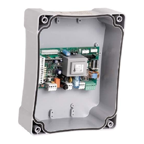
  • Page 37 à un niveau local. DÉCLARATION DE CONFORMITÉ CE Le soussigné Augusto Silvio Brunello, représentant légal de la société: TELCOMA S.r.l. Via Luigi Manzoni 11, 31015 Conegliano (TV) ITALIE Déclare que le produit: Modèle: T201 Emploi: Coffret pour motorisation des portails Est conforme aux impératifs essentiels de l'article 3 et aux dispositions de la Directive 1999/5/CE, s'il est employé...
  • Page 38 TAB. 1 (véanse Mor n. Mor n. Dispositivo I max Función Note El motor M1 se cierra con retardo. Motor M1 Común M1 230Vac En el caso de cancelas batientes, el motor M1 debe controlar la hoja con la electrocerradura. Motor M1 230Vac Cierra M1...
  • Page 39 TAB. 2 OFF ON Función Descripción Note • Durante la fase de apertura, pulsando el botón P/P, la cancela se bloquea; Abre - Stop - Cierra apretándolo de nuevo, se cierra. Durante la fase de cierre, pulsando el • botón P/P, la cancela se bloquea; apretándolo de nuevo, se abre. •...
  • Page 40 INSTRUCCIONES DE LA CENTRAL ELECTRONICA T101 Antes de realizar la instalación, se aconseja leer atentamente las presentes instrucciones. Un uso impropio del producto o un error de conexión podría comprometer el correcto funcionamiento del DESCRIPCIÓN DE LAS PIEZAS (Fig. 1) 1) Tablero de bornes para la conexión de la línea de alimentación.
  • Page 41 DATOS TECNICOS U.M. T201 Parámetros eléctricos Alimentación 230 ±10% Frecuencia Absorción stand-by (230V) Absorción máxima (230V) Potencia máx. motor 230V 1100 Temperatura de funcionamiento °C -20 +55 Dimensiones box (ANCH. x ALT. x PROF.) 200x255x100 INSTALACIÓN El equipo debe ser instalado CORRECTAMENTE por personal que posea los requisitos establecidos por las leyes vigentes y siguiendo las normativas EN12453 y EN12445 sobre la seguridad de la automatización.
  • Page 42 P/P, reinicia hacia el sentido de cierre. Conecte el encoder de los motores a los bornes de la T201, tal como se muestra en la fig. 2 y en la TAB. 1. Durante la programación de la carrera de la cancela, el led L1 intermitente certifica que la central ha detectado la presencia del encoder.
  • Page 43 El funcionamiento y la programación del receptor de LED1 LED2 la serie OC2 están mencionadas en las instrucciones indicadas en el mismo receptor. Tenga en cuenta que el canal 1 del receptor siempre corresponde al mando paso a paso (P/P) de la central, mientras que el canal 2 corresponde al mando peatones.
  • Page 44 TIPO 1 AUTOMATIZACIÓN DE 2 MOTORES SIN FINES DE CARRERA ELÉCTRICOS, SIN ENCODER Y SIN MAS200 Programación: 1 - Corte la alimentación de la central. 2 - Coloque la cancela en la mitad de la carrera. 4, 5 y 6 - Alimente la central manteniendo pulsado el botón STOP/PROG. hasta que se encienda el led L1 (detalle 8 el motor girase en el sentido contrario, corte la alimentación, invierta las fases del motor y repita el procedimiento).
  • Page 45 15 -Se abrirá automáticamente la hoja con el motor M2. 16 -Pulse el botón P/P cuando la hoja con el motor M2 complete la apertura. 18 -Transcurrido el tiempo de pausa deseado, pulse el botón P/P: el motor M2 comenzará la maniobra de cierre. 19 y 20 - Durante dicha maniobra habrá...
  • Page 46 Notas a tener en cuenta antes de la programación: Programación: 1 - Corte la alimentación de la central. 2 - Coloque la cancela en la mitad de la carrera. 4, 5 y 6 - Alimente la central manteniendo pulsado el botón STOP/PROG. hasta que se encienda el led L1 (detalle 8 Si está...
  • Page 47 TIPO 3 AUTOMATIZACIÓN DE 1 MOTOR SIN FINES DE CARRERA ELÉCTRICOS Y SIN ENCODER Notas a tener en cuenta antes de la programación: - Controle que el motor esté conectado en M1 (bornes 1 - 2 y 3) El módulo antiaplastamiento MAS200 debe insertarse únicamente después de haber hecho el procedimiento de autoaprendizaje.
  • Page 48 TIPO 4 AUTOMACIÓN DE 1 MOTOR CON FINES DE CARRERA ELÉCTRICO O ENCODER Notas a tener en cuenta antes de la programación: - Controle que el motor esté conectado en M1 (bornes 1 - 2 y 3) El módulo antiaplastamiento MAS200 debe insertarse únicamente después de haber hecho el procedimiento de autoaprendizaje.
  • Page 49 PROGRAMACIÓN DE LOS TIEMPOS DE DESACELERACIÓN PROGRAMACIÓN DE LA APERTURA PARA PEATONES (sólo para una automatización con un motor, dip 11 OFF) 1 y 2 - Con la cancela colocada en la mitad de su carrera, corte la alimentación de la central. 4, 5 y 6 - Alimente la central, manteniendo pulsado el botón STOP/PROG.
  • Page 50 TRIAC TEST La central T201 controla los motores a través del uso del TRIAC. La avería de este componente puede comprometer el funcionamiento y la seguridad de la instalación. Por este motivo, se ha introducido un control antes de cada maniobra. En caso de que haya alguna anomalía, la central se bloquea y la luz de aviso de cancela abierta ejecuta algunos parpadeos lentos.
  • Page 51 FUNCIONES ESPECIALES DE T201 Con unos procedimientos particulares, durante la fase de conexión de la central, se pueden introducir otras funciones. DESACELERACIÓN La T201 ofrece la posibilidad de obtener dos tipos de desaceleración: 1) Desaceleración normal 2) Desaceleración potenciada para automatizaciones pesadas.
  • Page 52 EXCLUSIÓN DE LA MEMORIA DE LOS TIEMPOS PARCIALES En esta versión de T201, es posible excluir la memoria de los tiempos parciales. Esta función es útil cuando el motor ya está provisto, en su interior, de un sistema de deceleración mecánico u oleodinámico (ejemplo: BLUES 21).
  • Page 53 - que no debe permitir que los niños jueguen en las cercanías de la automatización. Predisponga un programa de mantenimiento de la instalación (al menos cada 6 meses para los dispositivos de seguridad), La empresa TELCOMA Srl se reserva la facultad indiscutible de aportar, en cualquier momento, las...
  • Page 54 ámbito local DECLARACIÓN DE CONFORMIDAD CE El infrascrito Augusto Silvio Brunello, Representante legal de la empresa: TELCOMA S.r.l. dirección Via L. Manzoni 11, 31015 Conegliano (TV), ITALIA Declara que el producto: Modelo: T201 Empleo: Central de mando para abrecancela Es conforme a los requisitos esenciales del artículo 3 y a las correspondientes disposiciones de la Directiva...
  • Page 55 Mor n. Mor n. Device I max Function Notes The motor M1 is delayed for gate clo-sing. Motor M1 Common M1 230Vac In swing gate installa-tions the motor M1 should control theleaf with the electric lock. Motor M1 230Vac Close M1 Motor M1 Open M1 230Vac...
  • Page 56 TAB. 2 OFF ON Function Desciption Notes • During opening, upon pressing the P/P button the gate stops, pressing it Open - Stop - Close again the gate closes. During closing, upon pressing the P/P button the • gate stops, pressing it again the gate opens. •...
  • Page 57 INSTRUCTIONS FOR INSTALLING THE ELECTRONIC CONTROL UNIT T201 Please read these instructions carefully before installing the control unit. Improper use or a connection error could jeopardise correct operation of the product and endanger the end user. DESCRIPTION OF PARTS (Fig. 1) 1) Terminals for the connection of the mains supply 2) Line fuse 230V 6.3A (5x20)
  • Page 58 TECHNICAL DATA U.M. T201 Electrical parameters: Power supply 230 ±10% Frequency Stand-by input (230V) Maximum input (230V) Max. motor power 230V 1100 Working temperature °C -20 +55 Box size (W x H x D) 200x255x100 INSTALLATION legislation and incompliance with the standards EN12453 and EN12445 governing safety of the automation.
  • Page 59 Connect the motor encoders to the T201 terminals as shown in fig. 2 and TABLE 1. During the programming of the gate travel, the flashing of Led L1 signals that the control unit has detected the presence of the encoder.
  • Page 60 The operation and programming of the OC2 series LED1 LED2 receiver are described in the instructions attached to the receiver itself. Keep in mind that channel 1 on the receiver always corresponds to the step-by-step (P/P) control on the control unit, whereas channel 2 corresponds to the pedestrian control.
  • Page 61 TYPE 1 AUTOMATION OF 2 MOTORS WITHOUT ELECTRIC LIMIT SWITCHES, WITHOUT ENCODER AND WITHOUT MAS200 Programming: 1 - Disconnect the power supply to the control unit. 2 - Bring the gate to mid-travel position. the reverse direction, disconnect the power supply, exchange the motor phase wires and repeat the procedure). 8 and 9 - When it reaches the stop point press button P/P.
  • Page 62 16 -Press button P/P when the wing driven by motor M2 has opened all the way. 18 -When the desired pause time has elapsed, press button P/P: motor M2 will start closing. delay, press button P/P when the wing driven by motor M2 reaches the point where the wing driven by motor M1 should start moving.
  • Page 63 Before programming: - If limit switches are used, adjust them before executing the self-learning procedure. Programming: 1 - Disconnect the power supply to the control unit. 2 - Bring the gate to mid-travel position. in the reverse direction, disconnect the power supply, exchange the motor phase wires and repeat the procedure) 8 and 9 - When it reaches the stop point, motor M2 will stop while motor M1 will automatically start closing (wing with electric lock).
  • Page 64 TYPE 3 AUTOMATION OF 1 MOTOR WITHOUT ELECTRIC LIMIT SWITCHES AND WITHOUT ENCODER Before programming: - Make sure the motor is connected to M1 (terminals 1 - 2 and 3) The optional anti-crushing module MAS200 may be connected only after the self-learning procedure has been carried out.
  • Page 65 TYPE 4 AUTOMATION OF 1 MOTOR WITH ELECTRIC LIMIT SWITCHES OR ENCODER Before programming: - Make sure the motor is connected to M1 (terminals 1 - 2 and 3 ) - Adjust the limit switches before performing the self-learning procedure. he optional anti-crushing module MAS200 may be connected only after the self-learning procedure has been carried out.
  • Page 66 DECELARATION TIME PROGRAMMING If you wish to have decelerations values different from the factory settings, you must execute the time learning stage with before the wing reaches the end-of-travel position. PROGRAMMING OF PEDESTRIAN OPENING (only for automations with one motor, dip-switch 11 to OFF) 1 and 2 - When the gate is in mid-travel position, disconnect the power supply to the control unit.
  • Page 67 (e.g. mechanical clutch). TRIAC TEST The control unit T201 controls the motors through the TRIAC. This component is essential to the system operation and safety. If there is an anomaly, the control unit locks and the gate open indicator light blinks slowly.
  • Page 68 SELECTING THE DURATION OF THE RELEASE STROKE AND CLOSING STROKE Unit T201 allows you to increase the duration of the release and closing strokes by proceeding as follows: - disconnect the power supply to the control unit - while holding down the STOP/PROG. button, set dip-switch 10 from Off to On (if the dip-switch is already set to ON, turn it to Off and then back to On) After making your selection, release the STOP/PROG.
  • Page 69 SETTING THE SLOWDOWN RAMP The control unit is normally set to carry out optimal deceleration ramps for piston type motors, where the slowdown function is used. Should there be any jerking of the gate when passing from normal to slowdown speed or the passage is abrupt, this deceleration ramp may be changed as follows: - Cut off the power to the control unit.
  • Page 70 Prepare a maintenance schedule for the automation installation (at least once every 6 months for the safety devices), recording the work carried out in a special book. In line with its continual product improvement policy, both in aesthetic and functional terms, TELCOMA Srl reserves the right to make changes at any time without notice.
  • Page 71 Make enquiries concerning the recycling or disposal of the product, complying with the local laws in force. CE DECLARATION OF CONFORMITY The undersigned Augusto Silvio Brunello, Legal representative of the firm: TELCOMA S.r.l. Via Luigi Manzoni 11, 31015 Conegliano (TV) ITALY Declares that the product: Model: T201 Use: Gate operator control unit Complies with the essential requirements of section 3 and relative provisions of the Directive 1999/5/CE, if used for the purposes for which it has been designed.
  • Page 72 TAB. 1 (siehe Abb. 2) Mor n. Mor n. Vorrichtung I max Funktion Hinweise Die Schließzeit des Motors M1 wird verzö-gert. Motor M1 Gemein M1 230Vac Elektroschloss steuern. Motor M1 230Vac Schließen M1 Motor M1 Öffnen M1 230Vac Siehe Hinweise zum Motor Kondensator 230Vac Anlauf Motor M1...
  • Page 73 TAB. 2 (Detail 14 der Abb. 1) OFF ON Funktion Beschreinbung Hinweise • Während der Öffnung blockiert sich durch Drücken der Schritt-Tastedas Tor, Öffnen - Stop - Schließen durch erneutes Drücken schließt es sich. Während der Schließung blockiert sich • durch Drücken der Schritt-Taste das Tor,durch erneutes Drücken öffnet es sich.
  • Page 74 INSTALLATIONSANWEISUNGEN DER ELEKTRONISCHEN STEUEREINHEIT T201 Vor der Installation empfehlen wir, die vorliegenden Anweisungen aufmerksam durchzulesen. Eine unsachgemäße Anwendung des Produktes und ein fehlerhafter Anschluß können den einwandfreien Betrieb desselben und die Sicherheit des Endbenutzers beeinträchtigen. BESCHREIBUNG DER VERSCHIEDENEN TEILE (Abb. 1) 1) Klemmenleiste für Anschluss Stromversorgung...
  • Page 75 TECHNISCHE DATEN U.M. T201 Elektrische Parameter: Stromversorgung 230 ±10% Frequenz Stromaufnahme Stand-By (230V) Höchstaufnahmeleistung (230V) Höchstleistung Motor 230V 1100 Betriebstemperatur °C -20 +55 Abmessungen box (B x H x T) 200x255x100 INSTALLATION Die Apparaturmuss “FACHGERECHT” von Personal installiert werden, das über die gesetzlich verlangten - Sicher stellen, dass die Automatisierung überfür das Torgewicht korrekt bemessene Endanschläge verfügt.
  • Page 76 Antrieb in Öffnung blockiert ist, erfolgt automatisch eine kurze Schließbewegung; durch das Drücken der Taste P/P startet der Antrieb wieder in Schließung. Den Encoder der Antriebe an den Klemmen der T201 anschließen, gemäß der Abb. 2 und TAB. 1. Während der Programmierung des Torlaufs bestätigt die blinkende LED L1, dass die Steuerung das Vorhandensein des Encoders wahrgenommen hat.
  • Page 77 EMPFÄNGER OC2 (Det. 12 in Abb. 1) Die Funktionsweise und Programmierung des Empfängers LED1 LED2 der Serie OC2 sind in den Anweisungen im Empfänger angegeben. Bitte berücksichtigen, dass der Kanal 1 des Empfängers immer dem Befehl Schrittbetrieb (P/P) der Steuerung entspricht, wogegen der Kanal 2 dem Befehl PROGRAMMIERUNG DER ARBEITS - UND PAUSENZEITEN Die Zentrale erlernt die Arbeits- und Pausenzeiten während des Programmierungsmanövers selbst.
  • Page 78 TYP 1 AUTOMATION MIT 2 ANTRIEBEN OHNE ELEKTRISCHE ENDSCHALTER, ENCODER UND MAS200 Programmierung: 1 - Die Spannungsversorgung zur Steuerung abschalten. 2 - Das Tor auf Laufhälfte verschieben. 3 - Auf die Taste PROG./STOP drücken (Det. 21 in Abb. 1) 4, 5 und 6 -Die Spannungsversorgung zur Steuerung einschalten, Taste STOP/PROG gedrückt halten, bis LED L1 umgekehrt dreht, die Spannungsversorgung abschalten, die Phasen des Antriebs umkehren und das Verfahren wiederholen).
  • Page 79 15 -Der Antrieb M2 startet automatisch in Öffnung. 18 -Nach Ablauf der gewünschten Pausezeit, auf die Taste P/P drücken; der Antrieb M2 startet in Schließung. an dem der Antrieb M1 starten sollte. Der Antrieb M2 stoppt kurz und bewegt sich dann in Schließung. beendet hat.
  • Page 80 Wichtige Anmerkungen vor der Programmierung: Wenn Endschalter benutzt werden, müssen diese vor der Durchführung der Selbsterlernung eingestellt sein. Falls das Sondermodul MAS200 benutzt wird, ist sicher zu stellen, dass es je nach Antriebsmodell korrekt Programmierung: 1 - Die Spannungsversorgung zur Steuerung abschalten. 2 - Das Tor auf Laufhälfte verschieben.
  • Page 81 TYP 3 AUTOMATION MIT 1 ANTRIEB OHNE ELEKTRISCHE ENDSCHALTER UND OHNE ENCODER Wichtige Anmerkungen vor der Programmierung: - Prüfen, dass Dip Nr. 11 auf OFF gestellt ist (Det. 14 in Abb. 1) Das eventuelle Antiquetsch-Sondermodul MAS200 darf erst eingeschaltet sein, nachdem die Selbsterlernung ausgeführt ist.
  • Page 82 TYP 4 AUTOMATION MIT 1 ANTRIEB MIT ELEKTRISCHEN ENDSCHALTERN ODER ENCODER Wichtige Anmerkungen vor der Programmierung: - Prüfen, dass Dip Nr. 11 auf OFF gestellt ist (Det. 14 in Abb. 1) - Die Endschalter vor der Durchführung der Selbsterlernung einstellen. Das eventuelle Antiquetsch-Sondermodul MAS200 darf erst eingeschaltet sein, nachdem die Selbsterlernung ausgeführt ist.
  • Page 83 PROGRAMMIERUNG DER SOFT-STOPP-ZEITEN Falls man Soft-Stopps einstellen will, die anders sind als werkseitig eingestellt, muss die Erlernung der Zeiten ausgeführt werden, wobei Dip-Switch Nr. 9 (Det. 14 in Abb. 1) auf Pos. ON gestellt sein muss. erreicht hat, auf die Taste P/P (Det. 20 in Abb. 1) gedrückt werden. PROGRAMMIERUNG DER GEHFLÜGELÖFFNUNG (nur für Automationen mit einem Antrieb, Dip Nr.
  • Page 84 Fall müssen die Motoren eine eigene Regulierung der Kraft im Lieferumfang enthalten (z.B. mechanische Kupplung). TRIAC TEST Die Zentrale T201 steuert die Motoren durch Verwendung von TRIAC. Der Defekt dieses Bauteils kann den Betrieb und die Sicherheit der Anlage beeinträchtigen. Aus diesem Grund wurde eine Kontrolle vor jedem Manöver eingesetzt. Falls irgendeine Anomalie auftritt, blockiert die Zentrale und die Kontrolllampe Tor offen blinkt einige Malelangsam.
  • Page 85 Die Taste STOP/PROG loslassen, nachdem man gewählt hat. Die Steuerung wird speichern und den Normalbetrieb starten. AUSWAHL DER DAUER DES STOßES BEI ANLAUF UND SCHLIEßUNG An der T201 kann die Dauer des Stoßes bei Anlauf und Schließung wie folgend erhöht werden: - Die Spannungsversorgung zur Steuerung abschalten.
  • Page 86 ändert sich die Einstellung. AUSSCHLUSS DES TEILZEITEN-SPEICHERS Bei dieser Version des T201 kann der Teilzeiten -Speicher ausgeschlossen werden. Diese Funktion ist dann nützlich, wenn im Inneren des Motors bereits ein mechanisches oder öldynamisches Verlangsamungssystem (Beispiel BLUES 21) vorhanden ist.
  • Page 87 - dass Kind ernicht in der unmittelbaren Nähe der Automatisierung spielen dürfen Einen Wartungsplan für die Anlage vorbereiten (die Sicherheitsvorrichtung müssen mindestens alle 6 Monate gewartet werden) und die ausgeführten Wartungseingriffe in einem entsprechenden Verzeichnis anmerken. Die Firma TELCOMA Srl behält sich das unanfechtbare Recht vor, jederzeit Änderungen vorzunehmen, die sie...
  • Page 88 Informieren Sie sich, nach welchem Recycling-oder Entsorgungssystem das Produkt entsprechend der örtlich geltenden Bestimmungen zu entsorgen ist. CE-KONFORMITÄTSBESCHEINIGUNG Der Unterzeichner Augusto Silvio Brunello, gesetzlicher Vertreter der Firma: TELCOMA S.r.l. Via Luigi Manzoni 11, 31015 Conegliano (TV) ITALIEN erklärt hiermit, daß das Produkt: Modell: T201 Anwendung: Zentra le für Toröffnung wenn bestimmungsgemäß...
  • Page 89 TAB. 1 (zie Mor n. Mor n. Inrichting I max Functie Opmerkingen De motor M1 wordt tijdens het sluitenvertraagd. Motor M1 Gemeenschappelijk M1 230Vac Bij vleugelpoorten moet demotor M1 de poortvleugel met deelektrische vergrendeling besturen. Motor M1 230Vac Sluiten M1 Motor M1 Openen M1 230Vac...
  • Page 90 TAB. 2 OFF ON Funktie Bechrijving Opmerkingen • Door tijdens het openen op de Start/Stop-drukknop te drukken wordt de poortgeblokkeerd, door nogmaals op de knop te drukken sluit de poort. Openen - Stop - Sluiten • Door tijdens het sluiten op de Start/Stop-drukknop te drukken wordt de poort geblokkeerd, door nogmaals op de drukknop te drukken gaat de poort open.
  • Page 91 AANWIJZINGEN VOOR DE INSTALLATIE VAN DE ELEKTRONISCHE BESTURINGSKAST T201 Alvorens de besturingskast te installeren adviseren wij om deze aanwijzingen aandachtig te lezen. Door onjuist gebruik van het product of een foute aansluiting kan de juiste werking ervan en de vei- ligheid van de eindgebruiker in gevaar gebracht worden.
  • Page 92 TECHNISCHE DATEN U.M. T201 Elektrische Parameter: Stromversorgung 230 ±10% Frequenz Stromaufnahme Stand-By (230V) Höchstaufnahmeleistung (230V) Höchstleistung Motor 230V 1100 Betriebstemperatur °C -20 +55 Abmessungen box (B x H x T) 200x255x100 INSTALLATIE De apparatuur dient volgens de “REGELS VAN DE KUNST” geïnstalleerd te worden door monteurs die daartoe wettelijk bevoegd zijn en volgensde normen EN 12453 en EN 12445 inzake de veiligheid van de automatisering.
  • Page 93 P/P wordt gedrukt, start hij in sluitrichting. Sluit de encoder van de motoren op de klemmetjes van de T201 aan zoals dat te zien is op afb. 2 en TAB. 1. Tijdens het programmeren van de loop van de poort, geeft de knipperende led L1 aan dat de besturingseenheid de aanwezigheid van de encoder heeft geconstateerd.
  • Page 94 GEBRUIK ONTVANGER OC2 (deel 12 op afb. 1) Werking en programmering van de ontvanger serie LED1 LED2 OC2 vindt u in de aanwijzingen die met de ontvanger zijn meegeleverd. Denk eraan dat het kanaal 1 van de ontvanger altijd overeenkomt met de instructie stap-voor-stap (P/P) van de besturingseenheid en het kanaal 2 met de voetgangersopening.
  • Page 95 TYPE 1 AUTOMATISERING VAN 2 MOTOREN ZONDER ELEKTRISCHE EINDSCHAKELAARS, ZONDER ENCODER EN ZONDER MAS200 EENVOUDIGE PROGRAMMERING - dip 9 op OFF - deel 14 op afb. 1* Programmering: 1 - Schakel de stroomtoevoer naar de besturingseenheid uit. 2 - Zet de poort halverwege. 3 - Druk op de toets STOP/PROG.
  • Page 96 16 -Druk op de knop P/P wanneer de vleugel met de motor M2 bijna helemaal open is. 19 en 20 - Tijdens deze manoeuvre moet u de ruimte voor vertraging van de ene vleugel ten opzichte van de andere bij het sluiten bepalen. Voor het invoeren van die vertragingstijd drukt u op de knop P/P wanneer de vleugel met de motor M2 het punt heeft bereikt waarop de vleugel met de motor M1 zou moeten zou moeten starten.
  • Page 97 NL NL Opmerkingen voor het programmeren: Als de eindschakelaars worden gebruikt, dient u die af te stellen voordat u de herkenningsprocedure gaat uitvoeren. toegepaste model motor en dient u pas bij het programmeren de kracht op het maximum te zetten (deel 19 op afb. 1). Programmering: 1 - Schakel de stroomtoevoer naar de besturingseenheid uit.
  • Page 98 TYPE 3 AUTOMATISERING VAN 1 MOTOR ZONDER ELEKTRISCHE EINDSCHAKELAARS EN ZONDER ENCODER EENVOUDIGE PROGRAMMERING - dip 9 op OFF - deel 14 op afb. 1* Opmerkingen voor het programmeren: - Controleer dat u de dipschakelaar nr. 11 op de stand OFF hebt gezet (deel14 op afb.1). - Controleer dat u de motor op M1 hebt aangesloten (klemmetjes 1 - 2 en 3) De eventuele antiknelmodule MAS200 mag pas worden ingeschakeld nadat u de herkenningsprocedure hebt uitgevoerd.
  • Page 99 NL NL TYPE 4 AUTOMATISERING VAN 1 MOTOR MET ELEKTRISCHE EINDSCHAKELAARS OF ENCODER EENVOUDIGE PROGRAMMERING - dip 9 op OFF - deel 14 op afb. 1* Opmerkingen voor het programmeren: - Controleer dat u de dipschakelaar nr.11 op stand OFF hebt gezet (deel 14 op afb.1) - Controleer dat u de motor op M1 hebt aangesloten (klemmetjes 1 - 2 en 3) - Stel de eindschakelaars af voordat u de herkenningsprocedure gaat uitvoeren.
  • Page 100 PROGRAMMERING VAN DE VERTRAGINGSTIJDEN Indien u andere vertragingstijden wilt instellen dan die welke in de fabriek zijn ingesteld, dient u de herkenningsfase voor de tijden uit te voeren waarbij de dipschakelaar nr. 9 (deel 14 op afb. 1) op de stand ON staat. Tijdens de herkenningsfase dient u op de knop P/P (deel 20 op afb.1) te drukken op het punt waarop u wilt dat de vertraging begint, in ieder geval voordat de vleugel bij de eindschakelaar komt.
  • Page 101 TRIAC TEST De besturingskast T201 bestuurt de motoren met behulp van TRIAC. Door een storing aan dit onderdeel kan de werking en de veiligheid van de installatie in gevaar gebracht worden. Daarom is er vóór elke manoeuvre een controle opgenomen. Als er een storing is wordt de besturingskast geblokkeerd en knippert het controlelampje poort open een paar keer langzaam.
  • Page 102 SELECTIE DUUR ONTGRENDELINGSSLAG EN SLUITSLAG Bij het model T201 kunt u de duur van de ontgrendelingslag en sluitslag verlengen; u gaat hiervoor als volgt te werk: - schakel de stroomtoevoer naar de besturingseenheid uit - schakel de stroomtoevoer naar de besturingseenheid in en houd daarbij de toets STOP/PROG.
  • Page 103 Telkens als deze procedure herhaald wordt (RESET + P/P en STOP/PROG. 3 seconden lang ingedrukt) verandert de instelling. UITSCHAKELING VAN HET GEDEELTELIJKE TIJDGEHEUGEN Bij dit model van de T201 is het mogelijk om het gedeeltelijke tijdgeheugen uit te schakelen. Deze functie komt van pas als de motor reeds inwendig van een mechanisch of hydraulisch vertragingssysteem voorzien is (bijvoorbeeld BLUES 21).
  • Page 104 Er moet een onderhoudsplan van de installatie opgesteld worden (minimaal om de 6 maanden voor de beveiligingen) waarbij de uitgevoerde werkzaamheden ineenspeciaalregistergenoteerdmoetenworden. De firma TELCOMA S.r.l. behoudt zich het onaanvechtbare recht voor om op elk gewenst moment de veranderingen aan werking te verbeteren.
  • Page 105 Informeer over de wijze van hergebruik of verwijdering van het product en neem daarbij de wettelijke voorschriften die ter plaatse gelden in acht EG-VERKLARING VAN OVEREENSTEMMING Ondergetekende, Augusto Silvio Brunello, Wettelijk vertegenwoordiger van de firma: TELCOMA S.r.l. Via Luigi Manzoni 11, 31015 Conegliano (TV) ITALY Verklaart dat het product: Model: T201 Toepassing: Besturingskast voor poortopeners...
  • Page 108 L'entreprise Telcoma caso de arreglos improprios o utilizactión equivocada del Durante il periodo di garanzia la ditta Telcoma srl si impegna srl s'engange, durant la periode de garantie du produit, à producto. Durante el periodo de garantía, la empresa a riparare e/o sostituire le parti difettate e non manomesse.