Table des Matières

Publicité

Les langues disponibles
  • FR

Les langues disponibles

  • FRANÇAIS, page 59

Liens rapides

Betriebsanleitung | Operating instructions | Mode d'emploi |
Istruzioni per l'uso | Instrucciones de servicio | Bruksanvisning
Drehantrieb
Rotary actuator
Vérin rotatif
Attuatore rotante
Actuador de giro
Vriddon
RAK
R402005099/10.2014, Replaces: 09.2009, DE/EN/FR/IT/ES/SV

Publicité

Table des Matières
loading

Sommaire des Matières pour Emerson AVENTICS RAK

  • Page 1 Betriebsanleitung | Operating instructions | Mode d’emploi | Istruzioni per l'uso | Instrucciones de servicio | Bruksanvisning Drehantrieb Rotary actuator Vérin rotatif Attuatore rotante Actuador de giro Vriddon R402005099/10.2014, Replaces: 09.2009, DE/EN/FR/IT/ES/SV...
  • Page 3: Table Des Matières

    AVENTICS | RAK | R402005099–BDL–001–AB Inhalt Zu dieser Anleitung ............2 Weiterführende Dokumentation ........... 2 Zu Ihrer Sicherheit ............2 Bestimmungsgemäßer Gebrauch........3 Nicht bestimmungsgemäßer Gebrauch ......3 Qualifikation des Personals ........... 3 Warnhinweise................4 Das müssen Sie beachten ............4 Einsatzbereiche .............
  • Page 4: Zu Dieser Anleitung

    AVENTICS | RAK | R402005099–BDL–001–AB Zu dieser Anleitung Diese Anleitung enthält wichtige Informationen, um den Drehantrieb, Serie RAK, sicher und sachgerecht zu installieren und in Betrieb zu nehmen. Sie enthält auch Informationen zur Bedienung und Wartung sowie zur Behebung einfacher Störungen. Lesen Sie diese Anleitung, insbesondere Kapitel 2, ”Zu Ihrer Sicherheit”, auf Seite 2, sorgfältig durch, bevor Sie mit dem Drehantrieb, Serie RAK, arbeiten.
  • Page 5: Bestimmungsgemäßer Gebrauch

    AVENTICS | RAK | R402005099–BDL–001–AB Bestimmungsgemäßer Gebrauch Halten Sie die in den technischen Daten genannten Leistungsgrenzen ein. Setzen Sie den Drehantrieb, Serie RAK, bevorzugt im industriellen Bereich ein. Der bestimmungsgemäße Gebrauch schließt auch ein, dass Sie diese Anleitung und insbesondere das Kapitel „Zu Ihrer Sicherheit“ gelesen und verstanden haben.
  • Page 6: Warnhinweise

    AVENTICS | RAK | R402005099–BDL–001–AB Warnhinweise In dieser Anleitung stehen Warnhinweise vor einer Handlungsanweisung, bei der die Gefahr von Personen- oder Sachschäden besteht. Die beschriebenen Maßnahmen zur Gefahrenabwehr müssen eingehalten werden. Warnhinweise sind wie folgt aufgebaut: SIGNALWORT Art und Quelle der Gefahr Folgen bei Nichtbeachtung Maßnahme zur Gefahrenabwehr Warnzeichen, Signalwort...
  • Page 7: Einsatzbereiche

    AVENTICS | RAK | R402005099–BDL–001–AB Montagearbeiten noch nicht abgeschlossen sind und Sie die Montagestelle unbeaufsichtigt lassen müssen. Verlegen Sie die Leitungen so, dass niemand darüber stolpern kann. Bei der Stellen Sie sicher, dass alle pneumatischen Anschlüsse ordnungsgemäß belegt oder verschlossen sind. Inbetriebnahme Vergewissern Sie sich, dass der Drehantrieb und eventuell damit verbundene Teile ordnungsgemäß...
  • Page 8: Lieferumfang

    AVENTICS | RAK | R402005099–BDL–001–AB Lieferumfang Im Lieferumfang sind enthalten: Drehantrieb, Serie RAK, gemäß Bestellung Optionales Zubehör, gemäß Bestellung Informationen zu den erhältlichen Ausführungen und die Teilenummern finden Sie im Produktkatalog im Internet (www.aventics.com) oder im Hauptkatalog von AVENTICS. Gerätebeschreibung Der Drehantrieb, Serie RAK, ist ein doppeltwirkender Drehflügel- antrieb, der aus einem Grundkörper mit einer durchgehenden Welle und einem oder zwei Flügeln besteht.
  • Page 9: Drehantrieb, Serie Rak, Größe 1 Bis 5

    AVENTICS | RAK | R402005099–BDL–001–AB Drehantrieb, Serie RAK, Größe 1 bis 5 00133580 Abb. 1: Größe 1S, 2S, 3S, 4S, 5S, 5D 1 Drehantrieb 4 Magnet 2 Fußbefestigung 5 Sensoreinheit 3 Flanschbefestigung 6 Schutzdeckel für einstellbaren Anschlag...
  • Page 10: Drehantrieb, Serie Rak, Größe 6 Bis 8

    AVENTICS | RAK | R402005099–BDL–001–AB Drehantrieb, Serie RAK, Größe 6 bis 8 00133581 Abb. 2: Größe 6S, 6D, 7S, 7D, 8S, 8D 1 Drehantrieb 6 Schwenkarm mit Magnet 2 Fußbefestigung 7 Hydraulischer Stoßdämpfer 3 Flanschbefestigung 8 Schwenkarm ohne Magnet 4 Befestigungsblech 9 Schwenkarm mit Magnet 5 Sensorhalter mit Sensor Zubehör...
  • Page 11 AVENTICS | RAK | R402005099–BDL–001–AB 5.3.1 Flanschbefestigung Für jede Größe des Drehantrieb, Serie RAK, (siehe Produkt- katalog) ist jeweils eine Flanschgröße erhältlich. Die Flanschbefestigung für die Größen 2 und 3 kann in Schritten von ° zum Bezugsposition montiert werden. 5.3.2 Fußbefestigung Für jede Größe des Drehantrieb, Serie RAK, (siehe Produkt- katalog) ist jeweils eine Größe erhältlich.
  • Page 12 AVENTICS | RAK | R402005099–BDL–001–AB blech können zwei Sensoren mit Sensorhalter angebracht werden, um eine Anzeige bei maximalem Drehwinkel zu ermöglichen. Die Sensoren entsprechen dem Elektroniktyp CT-3 mit einer LED und einem PNP-Ausgang. 5.3.6 Hydraulischer Stoßdämpfer für die Größen 6 bis 8 Der hydraulische Stoßdämpfer sorgt für eine weiche und sanfte Abfederung der Drehbewegung.
  • Page 13: Montage

    AVENTICS | RAK | R402005099–BDL–001–AB Montage Jeder Drehantrieb, Serie RAK, ist für eine bestimmte Anwendung ausgelegt. Verwenden Sie den Drehantrieb niemals für andere Anwendungen, ohne vorher mit Hilfe des Online-Konfigurators im Internet (www.aventics.com) oder des Hauptkatalogs von AVENTICS eine Neuberechnung durchzuführen. Stellen Sie sicher, dass die in den technischen Daten angegebenen Maximalwerte für Betriebsdruck sowie für axiale und radiale Lagerbelastung nicht überschritten werden.
  • Page 14 AVENTICS | RAK | R402005099–BDL–001–AB WARNUNG Gefahr von Personen- und Sachschäden durch unkontrollierte Bewegungen! Wenn beim Einbau des Drehantriebs Druckluft angeschlossen ist, können Personen verletzt oder die Anlage beschädigt werden. Stellen Sie sicher, dass der relevante Anlagenteil drucklos ist, während der Drehantrieb montiert wird.
  • Page 15: Einstellbaren Anschlag Einbauen

    AVENTICS | RAK | R402005099–BDL–001–AB Einstellbaren Anschlag einbauen Der Drehantrieb in den Größen 2 bis 5 besitzt einen einstellbaren Anschlag bestehend aus einem Schwenkarm, der an der Welle auf der Rückseite des Drehantriebs befestigt ist, und zwei Anschlägen, die mit Stellschrauben eingestellt werden. Der Schwenkarm (1) und der Bezugspunktanschlag (2) sind bei Lieferung bereits eingebaut.
  • Page 16 AVENTICS | RAK | R402005099–BDL–001–AB 0013358 Abb. 6: Winkeleinstellung Tabelle 1: Winkeleinstellbereich Abb. 6, Winkel Einstellung Bezug ° Minimaler Drehwinkel ° Bezugspunktanschlag, Feineinstellung ±3 ° ° Drehwinkelanschlag, Feineinstellung bis +6 ° ° Drehwinkelanschlag bei max. Winkel bis +3 ° Befestigungsintervall °...
  • Page 17: Schutzdeckel Befestigen Für Größen 2 Bis 5

    AVENTICS | RAK | R402005099–BDL–001–AB Schutzdeckel befestigen für Größen 2 bis 5 Der Schutzdeckel für den Drehantrieb in den Größen 2 bis 5 wird am Gehäuse des Drehantriebs befestigt, um den einstellbaren Anschlag zu schützen, wenn keine Sensoren verwendet werden. Bei Verwendung von Sensoren wird stattdessen ein Sensor- gehäuse eingebaut (siehe “Sensoreinheit für Größen 1 bis 5 einbauen”...
  • Page 18 AVENTICS | RAK | R402005099–BDL–001–AB 00133593 Abb. 7: Sensoreinheit für Größen 1 bis 5 einbauen Tabelle 3: Anzugsdrehmoment, Sensoreinheit Für Größe Schraube für Gehäuse Schraube für Sensor 2 – 3 Ncm 40 – 50 Ncm 6 – 10 Ncm 40 – 50 Ncm 10 –...
  • Page 19: Sensor Für Größen 6 Bis 8 Einbauen

    AVENTICS | RAK | R402005099–BDL–001–AB Sensor für Größen 6 bis 8 einbauen Der Sensor für den Drehantrieb in den Größen 6 bis 8 wird mit Hilfe eines Sensorhalters und einer Befestigungsblech am Gehäuse des Drehantriebs angebracht. Sensor, Halter und Befestigungsblech werden separat bestellt und geliefert.
  • Page 20: Stoßdämpfer Und Schwenkarm Einbauen

    AVENTICS | RAK | R402005099–BDL–001–AB Stoßdämpfer und Schwenkarm einbauen Der hydraulische Stoßdämpfer sorgt zusammen mit einem Schwenkarm für Drehantriebe in den Größen 6 bis 8 für eine weiche und sanfte Abfederung der Drehbewegung. Der Schwenkarm wird an der Welle des Drehantriebs befestigt und ist für verschiedene Drehwinkel erhältlich (siehe Produktkatalog).
  • Page 21: Flanschbefestigung

    AVENTICS | RAK | R402005099–BDL–001–AB Tabelle 4: Anzugsdrehmoment für Stoßdämpferschrauben Für Größe Schraube Drehmoment M6 x 12 10 Nm M8 x 16 24 Nm M10 x 20 47 Nm Flanschbefestigung Befestigen Sie die Flanschbefestigung mit den beigelegten Schrauben an der Vorderseite des Drehantriebs. Der Flansch °...
  • Page 22: Fußbefestigung

    AVENTICS | RAK | R402005099–BDL–001–AB Fußbefestigung Befestigen Sie die Fußbefestigung mit den beigelegten Schrauben an der Vorderseite des Drehantriebs. Bei den Größen 1, 6, 7 und 8 kann auch eine Fußbefestigung an der Rückseite befestigt werden. Die Fußbefestigung für die Größen °...
  • Page 23: Inbetriebnahme

    AVENTICS | RAK | R402005099–BDL–001–AB Inbetriebnahme Die Inbetriebnahme darf nur durch eine Pneumatikfachkraft oder durch eine Person unter der Leitung und Aufsicht einer Fachkraft erfolgen (siehe “Qualifikation des Personals” auf Seite 3). VORSICHT Gefahr von Personen- oder Sachschäden bei nicht fachgerechter Montage! Nicht fachgerecht montierte Komponenten können sich im Betrieb lösen und andere Teile der Anlage beschädigen oder Personen verletzen.
  • Page 24: Druckluft Anschließen

    AVENTICS | RAK | R402005099–BDL–001–AB Druckluft anschließen Stellen Sie sicher, dass die Druckluftzufuhr abgeschaltet ist, und schließen Sie dann die Druckluftleitungen an. Stellen Sie sicher, dass der maximal zulässige Betriebsdruck nicht überschritten wird. Siehe “Technische Daten” auf Seite 26. Drehgeschwindigkeit einstellen ACHTUNG Gefahr von Sachschäden Ein Drehantrieb, der ohne Geschwindigkeitssteuerung betrieben wird, kann eine zu hohe...
  • Page 25: Demontage Und Austausch

    AVENTICS | RAK | R402005099–BDL–001–AB Demontage und Austausch Demontage Eine Demontage wird nur erforderlich, wenn das Gerät ersetzt oder entsorgt werden muss. Schalten Sie die gesamte Druckluft am relevanten Teil der Anlage ab. Entfernen Sie alle Geräte, die nicht zum Drehantrieb gehören. Nehmen Sie alle Anbauten ab und entfernen Sie den Drehantrieb vom betreffenden Anlagenteil.
  • Page 26: Reinigung Und Pflege

    AVENTICS | RAK | R402005099–BDL–001–AB Reinigung und Pflege ACHTUNG Feinstaub, korrosionsfördernde Gase, Lösemittel und aggressive Reinigungsmittel können zu Beschädigungen des Geräts führen. Durch die Verwendung aggressiver Chemikalien kann der Drehantrieb beschädigt oder seine Lebensdauer verkürzt werden. Verwenden Sie niemals Lösemittel oder aggressive Reinigungsmittel. Halten Sie Schleifstäube und korrosionsfördernde Gase vom Gerät fern.
  • Page 27: 10 Wenn Störungen Auftreten

    AVENTICS | RAK | R402005099–BDL–001–AB 10 Wenn Störungen auftreten WARNUNG Gefahr von Personen- und Sachschäden bei nicht fachgerecht ausgeführter Instandsetzung! Falsch ausgeführte Instandsetzungen oder Veränderungen des Drehantriebs können Personen- oder Sachschäden zur Folge haben. Verwenden Sie bei der Instandsetzung eines Drehantriebs ausschließlich Ersatzteile und Austauschbausätze aus dem Produktkatalog.
  • Page 28: 11 Technische Daten

    AVENTICS | RAK | R402005099–BDL–001–AB 11 Technische Daten Allgemeine Daten Abmessungen Konfigurationsabhängig, siehe Produktkatalog. Gewicht Konfigurationsabhängig, siehe Produktkatalog. +5 °C bis +60 °C Temperaturbereich für Anwendung –25 °C bis +75 °C Temperaturbereich Lagerung Schutzart nach EN 60529/IEC529 (gilt für IP67 eingebaute Sensoren) Betriebsdruck Größe 1S, 2S:1,5 —...
  • Page 29: 12 Index

    AVENTICS | RAK | R402005099–BDL–001–AB 12 Index Erforderliche Kenntnisse 3 Abfallentsorgung 23 Anschluss von Druckluft 22 Ausführungen 6 Fehlerbehebung 25 Austausch 23 Fehlersuche 25 Axiale Belastung 11 Flanschbefestigung 7, 8, 9, Axiales Lager 11 Flanschbefestigung befestigen 19 Belastung zu hoch 25 Fußbefestigung 7, 8, 9, 20 Beschreibung 6 Fußbefestigung...
  • Page 30 AVENTICS | RAK | R402005099–BDL–001–AB Stoßdämpfer 10 Magnet 7 einbauen 18 Maßnahmen bei Fehlern 25 Montage 11 Technische Daten 26 Temperatur 26 Öl im Drehantrieb 25 Undichtheit 25 Pflegen 24 Warnhinweise 4 Qualifikation 3 Wartung 24 Wasser Nutzung 24 Radiale Belastung 11 Wellenbelastung 12 Recycling 23 Winkel einstellen 13...
  • Page 31 AVENTICS | RAK | R402005099–BDL–001–AB Contents About this document ........... 30 Related documents..............30 For your safety ............31 Intended use ................31 Improper use ................31 Personnel qualifications ............32 Safety instructions..............32 Observe the following ............33 Applications ..............34 Delivery contents ............34 Device description ............
  • Page 32: About This Document

    AVENTICS | RAK | R402005099–BDL–001–AB About this document This instruction manual contains important information for the safe and appropriate installation and commissioning of Rotary actuator, series RAK. It also contains information about service and maintenance, and how to remedy simple malfunctions yourself.
  • Page 33: For Your Safety

    AVENTICS | RAK | R402005099–BDL–001–AB For your safety The rotary actuator, series RAK, has been manufactured in accordance with current engineering standards and safety regulations. Even so, there is a risk of injury or damage if the following general safety instructions and the specific warnings given in this instruction manual are not observed.
  • Page 34: Personnel Qualifications

    AVENTICS | RAK | R402005099–BDL–001–AB Personnel qualifications Installation, connection and commissioning require fundamental knowledge of electronics and pneumatics, as well as knowledge of the applicable technical terminology. For this reason, the device may only be installed, connected and commissioned by a specialist in electronics and pneumatics or by a person under the control and supervision of such a specialist.
  • Page 35: Observe The Following

    AVENTICS | RAK | R402005099–BDL–001–AB Observe the following General information Observe the local regulations to avoid workplace accidents and to protect the environment in the country of use. The Drehantrieb must never be altered or modified from its original configuration (not including mounting of accessories). The Drehantrieb may only be used within the technical data stated in the technical description.
  • Page 36: Applications

    AVENTICS | RAK | R402005099–BDL–001–AB Applications The rotary actuator, series RAK, is used for rotating movements in small space industrial applications. The Drehantrieb is a double acting rotary wing drive, which gives high torque in relation to size and price. The wide range of models and various accessories make it possible to optimize the function for most applications.
  • Page 37: Device Description

    AVENTICS | RAK | R402005099–BDL–001–AB Device description The rotary actuator, series RAK, is a double acting rotary wing drive and consists of a body with a through shaft and one or two wings. When compressed air is connected a rotating movement is performed.
  • Page 38: Rotary Actuator, Series Rak, Size 6 To 8

    AVENTICS | RAK | R402005099–BDL–001–AB Rotary actuator, series RAK, size 6 to 8 00133581 Fig. 2: Size 6S, 6D, 7S, 7D, 8S, 8D 1 Rotary actuator 6 Swivel arm with magnet 2 Foot mounting 7 Hydraulic shock absorber 3 Flange mounting 8 Swivel arm without magnet 4 Sensor mounting plate 9 Swivel arm with magnet...
  • Page 39: Flange Mounting

    AVENTICS | RAK | R402005099–BDL–001–AB 5.3.1 Flange mounting Available in one size for each size of rotary actuator, series RAK. See the product catalog. The flange mounting for size 2 and 3 can ° be mounted in steps of 120 from the reference position.
  • Page 40 AVENTICS | RAK | R402005099–BDL–001–AB 5.3.6 Hydraulic shock absorber, for size 6 to 8 The hydraulic shock absorber is used for a smooth and gentle cushioning of the rotating movement. The hydraulic shock absorber consists of an oil filled housing with two pistons that are influenced by a swivel arm fitted on the shaft of the Drehantrieb.
  • Page 41: Installation

    AVENTICS | RAK | R402005099–BDL–001–AB Installation Each rotary actuator, series RAK, is dimensioned for a particular application. Never use the Drehantrieb for another application without making a new calculation by using the on-line configurator on the Internet (www.aventics.com) or the main AVENTICS catalog. Check that the maximum values of working pressure and axial and radial bearing load stated in the technical specifications are not exceeded.
  • Page 42: Fitting The Adjustable Stop

    AVENTICS | RAK | R402005099–BDL–001–AB Fig. 4: Load directly on the shaft Make sure that the load is properly attached for the specific application, and that the attachment can handle the load for which the Drehantrieb is dimensioned. Fitting the adjustable stop The Drehantrieb size 2 to 5 has an adjustable stop that consists of a swivel arm, fitted on the shaft at the back end of the Drehantrieb, and two stoppers that are adjusted with screws.
  • Page 43 AVENTICS | RAK | R402005099–BDL–001–AB 00133603 Fig. 5: Fitting the adjustable stop Adjust the rotation angles with the fine-adjust screws. See Fig. 6 and Table 2 for angle adjustment range. Fit either the protective cover or sensor unit, available as accessories.
  • Page 44 AVENTICS | RAK | R402005099–BDL–001–AB 00133582 Fig. 6: Angle adjustment Table 1: Angle adjustment range Fig. 6, Angle Adjustment referenc ° Minimum oscillation angle ° Reference stopper, fine adjustment ±3 ° ° Angle adjustment stopper, fine adjustment to +6 ° °...
  • Page 45: Fitting The Protective Cover, For Size 2 To 5

    AVENTICS | RAK | R402005099–BDL–001–AB Fitting the protective cover, for size 2 to 5 The protective cover for Drehantrieb size 2 to 5 is fitted onto the rotary actuator housing to protect the adjustable stop when sensors are not used. When using sensors, a sensor housing is fitted instead (see “Fitting the sensor unit, for size 1 to 5”, below).
  • Page 46 AVENTICS | RAK | R402005099–BDL–001–AB 00133593 Fig. 7: Fitting the sensor unit, for size 1 to 5 Table 3: Tightening torque, sensor unit For size Screw for housing Screw for sensor 2 – 3 Ncm 40 – 50 Ncm 6 – 10 Ncm 40 –...
  • Page 47: Fitting The Sensor, For Size 6 To 8

    AVENTICS | RAK | R402005099–BDL–001–AB Fitting the sensor, for size 6 to 8 The sensor for Drehantrieb size 6 to 8 is fitted onto the Drehantrieb housing by using a sensor holder and a mounting plate. Sensor, holder and mounting plate are ordered and supplied separately. Two sensors with sensor holder can be fitted.
  • Page 48: Fitting The Shock Absorber And Swivel Arm

    AVENTICS | RAK | R402005099–BDL–001–AB Fitting the shock absorber and swivel arm The hydraulic shock absorber is used together with a swivel arm for Drehantriebs size 6 to 8, for a smooth and gentle cushioning of the rotating movement. The swivel arm is fitted onto the shaft of the Drehantrieb and is available for various oscillation angles (see the product catalog).
  • Page 49: Flange Mounting

    AVENTICS | RAK | R402005099–BDL–001–AB Flange mounting Fit the flange mounting to the front end of the rotary actuator using screws supplied. The flange for size 2 and 3 can be fitted ° in steps of 120 from the reference position. Attach the flange to a base by using suitable screws or bolts.
  • Page 50: Foot Mounting

    AVENTICS | RAK | R402005099–BDL–001–AB Foot mounting Fit the foot mounting to the front end of the rotary actuator using screws supplied. Size 1, 6, 7, and 8 can also be fitted with a foot mounting on the back end. The foot mounting for size 2, °...
  • Page 51: Commissioning

    AVENTICS | RAK | R402005099–BDL–001–AB Commissioning Commissioning may only be performed by a specialist in pneumatics or by a person under the control and supervision of such a specialist (see “Personnel qualifications”, page 32). CAUTION Risk of injury or damage in case of incorrect installation! Incorrectly installed components may come loose in service and damage other parts of the system, or injure personnel.
  • Page 52: Setting The Oscillation Speed

    AVENTICS | RAK | R402005099–BDL–001–AB Setting the oscillation speed NOTICE Risk of damage A Drehantrieb that is operated without speed control can reach too high oscillation speed, with risk of machine breakdown. Make sure that the Drehantrieb is always operated with speed control. Normally the oscillation speed is controlled by throttling the exhaust air from the Drehantrieb chambers with a check-choke valve.
  • Page 53: Removal And Replacement

    AVENTICS | RAK | R402005099–BDL–001–AB Removal and replacement Removal The only time removal will be necessary is when replacing or scrapping the device. Switch off all compressed air from the relevant part of the system. Remove any devices that do not belong to the Drehantrieb itself.
  • Page 54: Service And Maintenance

    AVENTICS | RAK | R402005099–BDL–001–AB Service and maintenance The rotary actuator, series RAK, is maintenance-free, if used within its technical specifications, and does not normally require any particular service or maintenance. Cleaning and care NOTICE The unit may be damaged by grinding dust, corrosive gas, solvents and aggressive cleaning agents.
  • Page 55: 10 If Malfunctions Occur

    AVENTICS | RAK | R402005099–BDL–001–AB 10 If malfunctions occur WARNING If a repair is not done properly there is a risk of injury or damage! Incorrect repair or modifications to the Drehantrieb may result in the risk of injury or damage.
  • Page 56: 11 Technical Data

    AVENTICS | RAK | R402005099–BDL–001–AB 11 Technical data General data Dimensions Depend on configuration; see product catalog. Weight Depends on configuration; see product catalog. +5 °C to +60 °C Operating temperature range –25 °C to +75 °C Storage temperature range Protection to EN 60529/IEC529 (applies to IP 67 fitted sensors)
  • Page 57: 12 Index

    AVENTICS | RAK | R402005099–BDL–001–AB 12 Index Accessories 36 End cover impacts 53 Action in the event of faults 53 Adjustable stop Fault-finding 53 fitting 40 Features 34 Adjustment of angles 41 Fitting adjustable stop 40 Angle adjustment 41, 42 Fitting flange mounting 47 Angle setting stopper 40 Fitting foot mounting 48...
  • Page 58 AVENTICS | RAK | R402005099–BDL–001–AB Sensor unit 35, 37 Magnet 35 fitting 43 Maintenance 52 Shaft load 40 Malfunction 53 Shock absorber fitting 46 Solvents 52 Oil in the cylinder 53 Speed control 50 Oscillation speed Swivel arm 36, 38 too high 53 Technical data 54 Pressure...
  • Page 59 AVENTICS | RAK | R402005099–BDL–001–AB Sommaire A propos de ce mode d’emploi ........58 Documentation supplémentaire .........58 Pour votre sécurité ............. 59 Utilisation conforme...............59 Utilisation non conforme............59 Qualification du personnel............60 Consignes de danger..............60 A respecter................61 Domaines d’application ..........62 Fourniture ..............62 Description de l’appareil ..........
  • Page 60: Propos De Ce Mode D'emploi

    AVENTICS | RAK | R402005099–BDL–001–AB A propos de ce mode d’emploi Ce mode d’emploi contient des informations importantes pour installer et mettre en service le vérin rotatif, série RAK, de manière sûre et conforme. Il contient aussi des informations sur l’utilisation et l’entretien ainsi que sur la réparation de défaillances simples.
  • Page 61: Pour Votre Sécurité

    AVENTICS | RAK | R402005099–BDL–001–AB Pour votre sécurité Le vérin rotatif, série RAK, a été fabriqué conformément aux techniques les plus modernes et aux règles de sécurité technique reconnues. Des dommages matériels ou corporels peuvent néanmoins survenir si les consignes de sécurité générales suivantes ainsi que les avertissements précédant les consignes d’utilisation contenus dans les présentes instructions ne sont pas respectées.
  • Page 62: Qualification Du Personnel

    AVENTICS | RAK | R402005099–BDL–001–AB Qualification du personnel Le montage, le raccordement et la mise en service exigent des connaissances électriques et pneumatiques fondamentales, ainsi que des connaissances concernant les termes techniques adéquats. Le montage, le raccordement et la mise en service ne doivent donc être effectués que par du personnel spécialisé...
  • Page 63: A Respecter

    AVENTICS | RAK | R402005099–BDL–001–AB A respecter Consignes générales Respecter les dispositions relatives à la prévention des accidents et à la protection de l’environnement applicables dans le pays d’utilisation et au poste de travail respectifs. La configuration d’origine du vérin rotatif ne doit pas être modifiée (indication non valable pour le montage d’accessoires).
  • Page 64: Domaines D'application

    AVENTICS | RAK | R402005099–BDL–001–AB Domaines d’application Le vérin rotatif, série RAK, s’emploie pour des rotations dans des domaines industriels à l’espace limité. Le vérin rotatif est un entraînement rotatif à palettes à double effet qui, pour sa taille et son prix, offre un couple élevé.
  • Page 65: Description De L'appareil

    AVENTICS | RAK | R402005099–BDL–001–AB Description de l’appareil Le vérin rotatif, série RAK, est un entraînement rotatif à palettes à double effet composé d’un corps de base et d’arbre sans fin ainsi que d’une ou de deux palettes. Un mouvement rotatif a lieu lors du raccordement de l’entraînement à...
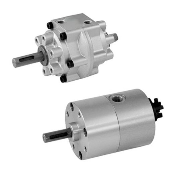
  • Page 66: Vérin Rotatif, Série Rak, Tailles 1 À 5

    AVENTICS | RAK | R402005099–BDL–001–AB Vérin rotatif, série RAK, tailles 1 à 5 00133580 Fig. 1: Tailles 1S, 2S, 3S, 4S, 5S, 5D 1 Vérin rotatif 4 Aimant 2 Fixation par patte d’équerre 5 Unité de capteurs 3 Fixation par bride 6 Couvercle de protection pour butée réglable...
  • Page 67: Vérin Rotatif, Série Rak, Tailles 6 À 8

    AVENTICS | RAK | R402005099–BDL–001–AB Vérin rotatif, série RAK, tailles 6 à 8 00133581 Fig. 2: Tailles 6S, 6D, 7S, 7D, 8S, 8D 1 Vérin rotatif 6 Bras pivotant avec aimant 2 Fixation par patte d’équerre 7 Amortisseur hydraulique 3 Fixation par bride 8 Bras pivotant sans aimant 4 Plaque de fixation de capteur 9 Bras pivotant avec aimant...
  • Page 68: Fixation Par Bride

    AVENTICS | RAK | R402005099–BDL–001–AB 5.3.1 Fixation par bride Une taille de bride est disponible pour chaque taille du vérin rotatif, série RAK (voir catalogue de produits). Pour les tailles 2 et 3, il est ° possible de monter la fixation par brides par paliers de 120 à...
  • Page 69 AVENTICS | RAK | R402005099–BDL–001–AB capteurs avec supports afin de permettre l’affichage de l’angle de rotation maximum. Les capteurs correspondent au type électronique CT-3, avec une DEL et une sortie PNP. 5.3.6 Amortisseur hydraulique pour les tailles 6 à 8 L’amortisseur hydraulique assure un amortissement souple et léger du mouvement rotatif.
  • Page 70: Montage

    AVENTICS | RAK | R402005099–BDL–001–AB Montage Chaque vérin rotatif, série RAK est conçu pour une application spécifique. Ne jamais utiliser le vérin rotatif pour d’autres applications que celle spécifiée sans avoir au préalable effectué un nouveau calcul à l’aide du configurateur en ligne sur Internet (www.aventics.com) ou du catalogue principal de AVENTICS.
  • Page 71 AVENTICS | RAK | R402005099–BDL–001–AB AVERTISSEMENT Risque de dommages corporels et matériels dus à des mouvements incontrôlés ! Si l’air comprimé est raccordé lors du montage du vérin rotatif, des personnes peuvent se blesser et l’installation peut être endommagée. S’assurer que la partie pertinente de l’installation est sans pression, pendant le montage du vérin rotatif.
  • Page 72: Montage De La Butée Réglable

    AVENTICS | RAK | R402005099–BDL–001–AB Montage de la butée réglable Le vérin rotatif de tailles 2 à 5 possède une butée réglable composée d’un bras pivotant fixé à l’arbre au dos du vérin rotatif, et de deux butées réglées à l’aide de vis de réglage. Le bras pivotant (1) et la butée du point de référence (2) sont déjà...
  • Page 73 AVENTICS | RAK | R402005099–BDL–001–AB 00133582 Fig. 6: Réglage des angles Tableaux 1: Plage de réglage des angles Fig. 6, Angle Réglage référence ° Angle de rotation minimum ° Butée du point de référence, réglage de ±3 précision ° ° Butée de l’angle de rotation, réglage de à...
  • Page 74: Fixation Du Couvercle De Protection, Tailles 2 À 5

    AVENTICS | RAK | R402005099–BDL–001–AB Fixation du couvercle de protection, tailles 2 à 5 Pour le vérin rotatif de tailles 2 à 5, le couvercle de protection est fixé au boîtier du vérin rotatif afin de protéger la butée réglable lorsqu’aucun capteur n’est utilisé.
  • Page 75 AVENTICS | RAK | R402005099–BDL–001–AB 00133593 Fig. 7: Montage de l’unité de capteurs pour tailles 1 à 5 Tableaux 3: Couple de serrage, unité de capteurs Pour taille Vis pour boîtier Vis pour capteur 2 – 3 Ncm 40 – 50 Ncm 6 –...
  • Page 76: Montage Du Capteur Pour Tailles 6 À 8

    AVENTICS | RAK | R402005099–BDL–001–AB Montage du capteur pour tailles 6 à 8 Pour le vérin rotatif de tailles 6 à 8, le capteur doit être monté sur le boîtier du vérin rotatif à l’aide d’un support de capteur et d’une plaque de fixation.
  • Page 77: Montage De L'amortisseur Et Du Bras Pivotant

    AVENTICS | RAK | R402005099–BDL–001–AB Montage de l’amortisseur et du bras pivotant En combinaison avec un bras pivotant, l’amortisseur hydraulique pour vérins rotatifs de tailles 6 à 8 assure un amortissement souple et léger du mouvement rotatif. Le bras pivotant se fixe à l’arbre du vérin rotatif et et disponible pour différents angles de rotation (voir catalogue de produits).
  • Page 78: Fixation Par Bride

    AVENTICS | RAK | R402005099–BDL–001–AB Tableaux 4: Couple de serrage pour vis d’amortisseur Pour taille Couple M6 x 12 10 Nm M8 x 16 24 Nm M10 x 20 47 Nm Fixation par bride Fixer la fixation par bride à la face avant du vérin rotatif à l’aide des vis fournies.
  • Page 79: Fixation Par Patte D'équerre

    AVENTICS | RAK | R402005099–BDL–001–AB Fixation par patte d’équerre Fixer la fixation par patte d’équerre à la face avant du vérin rotatif à l’aide des vis fournies. Pour les tailles 1, 6, 7 et 8, il est également possible de fixer une fixation par patte d’équerre par le dos.
  • Page 80: Mise En Service

    AVENTICS | RAK | R402005099–BDL–001–AB Mise en service La mise en service ne doit être effectuée que par un personnel spécialisé en pneumatique ou par une personne sous la direction et surveillance d’une personne qualifiée (voir « Qualification du personnel » à la page 60). ATTENTION ! Risque de dommages corporels ou matériels en cas de montage non conforme ! Des composants montés de manière non conforme peuvent se détacher en cours de...
  • Page 81: Raccordement De L'air Comprimé

    AVENTICS | RAK | R402005099–BDL–001–AB Raccordement de l’air comprimé S’assurer que l’alimentation en air comprimé est bien coupée, puis raccorder les conduites d’air comprimé. S’assurer que la pression de service maximale autorisée n’est pas dépassée. Voir « Données techniques » à la page 83. Réglage de la vitesse de rotation REMARQUE Risque de dommages matériels...
  • Page 82: Démontage Et Remplacement

    AVENTICS | RAK | R402005099–BDL–001–AB Démontage et remplacement Démontage Le démontage est nécessaire uniquement s’il faut remplacer ou jeter l’appareil. Désactiver complètement l’air comprimé sur la partie pertinente de l’installation. Retirer tous les appareils n’appartenant pas au vérin rotatif. Démonter toutes les pièces rajoutées et retirer le vérin rotatif de la partie de l’installation concernée.
  • Page 83: Nettoyage Et Entretien

    AVENTICS | RAK | R402005099–BDL–001–AB Nettoyage et entretien REMARQUE Les particules de poussière, gaz corrosifs, solvants et produits de nettoyage agressifs peuvent endommager l’appareil. L’utilisation de produits chimiques agressifs peut endommager le vérin rotatif ou en réduire la durée de vie. Ne jamais utiliser des solvants ou des détergents agressifs.
  • Page 84: 10 En Cas De Défaillances

    AVENTICS | RAK | R402005099–BDL–001–AB 10 En cas de défaillances AVERTISSEMENT ! Risque de dommages corporels et matériels en cas de réparations effectuées de manière non conforme ! Des réparations ou modifications effectuées de manière incorrecte sur le vérin rotatif peuvent entraîner des dommages corporels et matériels.
  • Page 85: 11 Données Techniques

    AVENTICS | RAK | R402005099–BDL–001–AB 11 Données techniques Données générales Dimensions En fonction de la configuration, voir le catalogue de produits. Poids En fonction de la configuration, voir le catalogue de produits. +5 °C à +60 °C Plage de température pour application –25 °C à...
  • Page 86: 12 Index

    AVENTICS | RAK | R402005099–BDL–001–AB 12 Index Données 83 Accessoires 65 Données techniques 83 Aimant 64 Douille 68 Amortisseur Montage 75 Amortisseur Utilisation 81 hydraulique 65, 67 Elimination des déchets 80 Entretien 81 Bras pivotant 65, 67 Erreurs 82 Butée réglable Montage 70 Fixation de la patte d’équerre 77...
  • Page 87 AVENTICS | RAK | R402005099–BDL–001–AB Limite du point de Raccordement de l’air référence 70 comprimé 79 Limiteur de débit Vérification 81 unidirectionnel 79 Réalisation 63 Recyclage 80 Maintenance 81 Réglage de l’angle 70, 71 Mesures en cas de Remplacement 80 défauts 82 Réparations 82 Mise en service 78...
  • Page 89 AVENTICS | RAK | R402005099–BDL–001–AB Indice analitico Spiegazione delle istruzioni ........88 Ulteriore documentazione............88 Per la vostra sicurezza ..........88 Utilizzo a norma...............89 Utilizzo non a norma ..............89 Qualifica del personale............89 Avvertenze di sicurezza ............89 Cosa bisogna osservare ............90 Campi di impiego ............91 Fornitura ..............
  • Page 90: Spiegazione Delle Istruzioni

    AVENTICS | RAK | R402005099–BDL–001–AB Spiegazione delle istruzioni Queste istruzioni contengono informazioni importanti per installare e mettere in funzione l'attuatore rotante, serie RAK nel rispetto delle norme e della sicurezza. Contengono inoltre informazioni sull'utilizzo e la manutenzione e sulla riparazione di piccoli guasti.
  • Page 91: Utilizzo A Norma

    AVENTICS | RAK | R402005099–BDL–001–AB Utilizzo a norma Rispettare i limiti di potenza riportati nei dati tecnici. Impiegare l'attuatore rotante, serie RAK di preferenza in ambiente industriale. L’uso a norma comprende anche la lettura e la comprensione di queste istruzioni ed in particolar modo del capitolo “Per la vostra sicurezza”.
  • Page 92: Cosa Bisogna Osservare

    AVENTICS | RAK | R402005099–BDL–001–AB Le avvertenze sono strutturate nel modo seguente: PAROLA DI SEGNALAZIONE Tipo di pericolo Conseguenze Protezione Parola di segnalazione Campo di applicazione Indica una situazione potenzialmente pericolosa che, se AVVERTENZA non evitata, può provocare lesioni gravi o addirittura la morte Indica una situazione potenzialmente pericolosa che, se ATTENZIONE...
  • Page 93: Campi Di Impiego

    AVENTICS | RAK | R402005099–BDL–001–AB collegate a quest'ultimo siano fissati correttamente. All'avvio aumentare la pressione lentamente e utilizzare il comando della velocità. Durante il In determinati campi di applicazione ed ambienti di installazione può sussistere il pericolo di schiacciamenti. funzionamento Attenersi sempre alle disposizioni di sicurezza del luogo.
  • Page 94: Fornitura

    AVENTICS | RAK | R402005099–BDL–001–AB Fornitura Sono compresi nella fornitura: attuatore rotante, serie RAK, come da ordinazione Accessori opzionali, come da ordinazione Le informazioni sulle versioni disponibili e i codici sono riportati nel catalogo prodotti in Internet o nel catalogo principale di AVENTICS.
  • Page 95: Attuatore Rotante, Serie Rak, Grandezze Da 1 A 5

    AVENTICS | RAK | R402005099–BDL–001–AB Attuatore rotante, serie RAK, grandezze da 1 a 5 00133580 Fig. 1: Grandezza 1S, 2S, 3S, 4S, 5S, 5D 1 Attuatore rotante 4 Magnete 2 Fissaggio a piedini 5 Unità sensori 3 Fissaggio a flangia 6 Coperchio protettivo per arresto regolabile...
  • Page 96: Attuatore Rotante, Serie Rak, Grandezze Da 6 A 8

    AVENTICS | RAK | R402005099–BDL–001–AB Attuatore rotante, serie RAK, grandezze da 6 a 8 00133581 Fig. 2: Grandezza 6S, 6D, 7S, 7D, 8S, 8D 1 Attuatore rotante 6 Braccio oscillante con magnete 2 Fissaggio a piedini 7 Ammortizzatore idraulico 3 Fissaggio a flangia 8 Braccio oscillante senza magnete 4 Piastra per fissaggio sensori 9 Braccio oscillante con magnete...
  • Page 97: Fissaggio A Flangia

    AVENTICS | RAK | R402005099–BDL–001–AB 5.3.1 Fissaggio a flangia Per ogni grandezza dell'attuatore rotante, serie RAK (ved. catalogo prodotti) è disponibile una flangia di grandezza diversa. Il fissaggio a flangia per le grandezze 2 e 3 può essere montata in passi di °...
  • Page 98: Montaggio

    AVENTICS | RAK | R402005099–BDL–001–AB essere sistemati due sensori con portasensori per poter indicare il raggiungimento dell'angolo massimo di rotazione. I sensori sono del tipo CT-3 con un LED ed un'uscita PNP. 5.3.6 Ammortizzatore idraulico per le grandezze da 6 a 8 L'ammortizzatore idraulico assicura un ammortizzamento morbido e leggero del movimento di rotazione.
  • Page 99 AVENTICS | RAK | R402005099–BDL–001–AB 00133601 Fig. 3: Ripartizione del carico pesante 1 Attuatore rotante 1 Attuatore rotante 2 Carico assiale 2 Carico radiale 3 Cuscinetto assiale 3 Boccola AVVERTENZA Pericolo di danni a cose o persone dovuto a movimenti incontrollati! Se al momento del montaggio dell'attuatore rotante l'aria compressa è...
  • Page 100: Montaggio Di Un Arresto Regolabile

    AVENTICS | RAK | R402005099–BDL–001–AB Fig. 4: Carico direttamente sull'albero Assicurarsi che il carico per l'applicazione corrispondente sia fissato correttamente e che il fissaggio possa supportare il carico per cui è predisposto l'attuatore rotante. Montaggio di un arresto regolabile L'attuatore rotante nelle grandezze da 2 a 5 presenta un arresto regolabile, costituito da un braccio oscillante fissato all'albero dell'attuatore rotante nella parte posteriore e due arresti regolati da una vite di regolazione.
  • Page 101 AVENTICS | RAK | R402005099–BDL–001–AB 00133603 Fig. 5: Montare un arresto regolabile Regolare l'angolo di rotazione servendosi delle viti a regolazione fine. Vedere Campo di regolazione dell'angolo nella Fig. 6 e Tabella 1. Applicare il coperchio protettivo oppure l'unità sensori, disponibili come accessori.
  • Page 102 AVENTICS | RAK | R402005099–BDL–001–AB 00133582 Fig. 6: Regolazione dell'angolo Tab. 1: Campo di regolazione dell'angolo Fig. 6, Angolare Impostaz. riferim. ° Angolo di rotazione minimo ° Arresto punto di riferimento, regolazione fine ±3 ° ° Arresto angolo di rotazione, regolazione fine da -9 a +6 °...
  • Page 103: Fissaggio Del Coperchio Protettivo, Grandezze

    AVENTICS | RAK | R402005099–BDL–001–AB Fissaggio del coperchio protettivo, grandezze da 2 a 5 Il coperchio protettivo per l'attuatore rotante nelle grandezze da 2 a 5 viene fissato al corpo dell'attuatore rotante per proteggere l'arresto regolabile, quando non vengono utilizzati sensori. Quando si usano invece dei sensori, viene montata una scatola sensori (vedere "Montaggio dell'unità...
  • Page 104 AVENTICS | RAK | R402005099–BDL–001–AB 00133593 Fig. 7: Montare l'unità sensori per le grandezze da 1 a 5 Tab. 3: Coppia di serraggio, unità sensori Per grandezza Vite per corpo Vite per sensore 2 – 3 Ncm 40 – 50 Ncm 6 –...
  • Page 105: Montaggio Del Sensore, Grandezze Da 6 A 8

    AVENTICS | RAK | R402005099–BDL–001–AB Montaggio del sensore, grandezze da 6 a 8 Il sensore per l'attuatore rotante nelle grandezze da 6 a 8 viene applicato al corpo dell'attuatore rotante con un portasensori ed una piastra di fissaggio. Il sensore, il portasensori e la piastra di fissaggio vengono ordinati e forniti separatamente.
  • Page 106: Montaggio Dell'ammortizzatore E Del Braccio Oscillante

    AVENTICS | RAK | R402005099–BDL–001–AB Montaggio dell'ammortizzatore e del braccio oscillante Per attuatori rotanti nelle grandezze da 6 a 8 l'ammortizzatore idraulico insieme ad un braccio oscillante garantisce un'ammor- tizzamento morbido e leggero del movimento di rotazione. Il braccio oscillante viene fissato all'albero dell'attuatore rotante ed è...
  • Page 107: Fissaggio A Flangia

    AVENTICS | RAK | R402005099–BDL–001–AB Fissaggio a flangia Fissare il fissaggio a flangia sulla parte anteriore dell'attuatore rotante con le viti fornite. Il fissaggio a flangia per le grandezze ° 2 e 3 può essere fissata solo in passi di 120 rispetto al posizione di riferimento.
  • Page 108: Fissaggio A Piedini

    AVENTICS | RAK | R402005099–BDL–001–AB Fissaggio a piedini Fissare il fissaggio a piedini sulla parte anteriore dell'attuatore rotante con le viti fornite. Per le grandezze 1, 6, 7 e 8 può essere fissata anche un fissaggio a piedini sulla parte posteriore.
  • Page 109: Messa In Funzione

    AVENTICS | RAK | R402005099–BDL–001–AB Messa in funzione La messa in funzione deve essere eseguita solo da personale specializzato in materia pneumatica o da una persona sotto la guida e la sorveglianza di personale qualificato (vedere “Qualifica del personale” a pagina 89). ATTENZIONE Pericolo di danni a persone o cose in caso di montaggio non corretto! Componenti non montati correttamente possono staccarsi durante il funzionamento e...
  • Page 110: Collegamento Dell'aria Compressa

    AVENTICS | RAK | R402005099–BDL–001–AB Collegamento dell’aria compressa Assicurarsi che l'alimentazione dell'aria compressa sia disattivata e collegare quindi le relative condutture. Assicurarsi che la pressione d'esercizio massima consentita non venga superata. Ved. “Dati tecnici” a pagina 112. Regolazione della velocità di rotazione NOTA Pericolo di danni a cose Un attuatore rotante azionato senza il comando della velocità...
  • Page 111: Smontaggio E Sostituzione

    AVENTICS | RAK | R402005099–BDL–001–AB Smontaggio e sostituzione Smontaggio Uno smontaggio è necessario solo se l'apparecchio deve essere sostituito o eliminato. Togliere completamente l'alimentazione pneumatica dalla parte rilevante dell'impianto. Rimuovere tutti gli apparecchi che non fanno parte dell'attuatore rotante. Rimuovere tutte le sovrastrutture e quindi l'attuatore rotante dalla parte dell'impianto in questione.
  • Page 112: Pulizia E Cura

    AVENTICS | RAK | R402005099–BDL–001–AB Pulizia e cura NOTA Polveri sottili, gas corrosivi, solventi e detergenti aggressivi possono danneggiare l'apparecchio. Utilizzando agenti chimici aggressivi, l'attuatore rotante può essere danneggiato o la sua vita utile accorciata. Non usare mai solventi o detergenti aggressivi. Tenere lontano dall'apparecchio il pulviscolo di rettifica e i gas corrosivi.
  • Page 113: 10 In Caso Di Disturbi

    AVENTICS | RAK | R402005099–BDL–001–AB 10 In caso di disturbi AVVERTENZA Pericolo di danni a persone e cose in caso di riparazione non a norma! Riparazioni inadeguate o modifiche all'attuatore rotante possono comportare danni a persone o cose. Per la riparazione dell'attuatore rotante utilizzare esclusivamente ricambi e set di ricambi del catalogo prodotti.
  • Page 114: 11 Dati Tecnici

    AVENTICS | RAK | R402005099–BDL–001–AB 11 Dati tecnici Dati generali Dimensioni In base alla configurazione, vedere il catalogo prodotti. Peso In base alla configurazione, vedere il catalogo prodotti. +5 °C a +60 °C Campo temperatura per applicazione –25 °C a +75 °C Campo temperatura magazzinaggio Tipo di protezione secondo EN 60529/ IP 67...
  • Page 115: 12 Indice

    AVENTICS | RAK | R402005099–BDL–001–AB 12 Indice Accessori 94 Dati tecnici 112 Acqua Descrizione Utilizzo 110 dell’apparecchio 92 Ammortizzatore Detergenti 110 Montaggio 104 Disturbo 111 Ammortizzatore idraulico 94, 96 Arresto del punto di Esecuzioni 92 riferimento 98 Arresto dell'angolo di rotazione 98 Fissaggio a flangia 93, 94, Arresto regolabile...
  • Page 116 AVENTICS | RAK | R402005099–BDL–001–AB dell'ammortizzatore 104 Smaltimento dei rifiuti 109 Montaggio dell'unità Smontaggio 109 sensori 101 Solventi 110 Montaggio di un arresto Sostituzione 109 regolabile 98 Temperatura 112 Olio nell'attuatore Tipo di protezione 112 rotante 111 Unità sensori 93, 95 Piastra per fissaggio Montaggio 101 sensori 94, 96...
  • Page 117 AVENTICS | RAK | R402005099–BDL–001–AB Índice Acerca de estas instrucciones ......... 116 Otra documentación ............116 Para su seguridad ............. 117 Utilización conforme a las especificaciones....117 Utilización no conforme a las especificaciones ..117 Cualificación del personal ..........118 Advertencias................
  • Page 118: Acerca De Estas Instrucciones

    AVENTICS | RAK | R402005099–BDL–001–AB Acerca de estas instrucciones Estas instrucciones contienen información importante para instalar y poner en servicio el Actuador de giro, serie RAK, de un modo seguro y apropiado. Contienen también información sobre el manejo y el mantenimiento así como sobre la eliminación de averías sencillas.
  • Page 119: Para Su Seguridad

    AVENTICS | RAK | R402005099–BDL–001–AB Para su seguridad El actuador de giro, serie RAK, se ha fabricado de acuerdo al estado actual de la técnica y las normas de seguridad técnica reconocidas. A pesar de ello, existe peligro de daños personales y materiales si no se tienen en cuenta las indicaciones de seguridad a continuación ni los carteles de advertencia ante indicaciones de manejo que aparecen en estas instrucciones.
  • Page 120: Cualificación Del Personal

    AVENTICS | RAK | R402005099–BDL–001–AB Cualificación del personal Es necesario tener conocimientos básicos de electrónica y neumática, así como conocimientos de la terminología técnica pertinente para realizar el montaje, la conexión y la puesta en servicio. Por lo tanto, solamente personal cualificado en electrónica o neumática o bien otra persona guiada y supervisada por una persona cualificada podrá...
  • Page 121: Cabe Tener En Cuenta

    AVENTICS | RAK | R402005099–BDL–001–AB Cabe tener en cuenta Indicaciones Observe las prescripciones vigentes para evitar accidentes y respetar el medio ambiente en el país en el que se vaya a generales utilizar el sistema y en el puesto de trabajo. La configuración original del actuador de giro no debe cambiar-se o modificarse (no es válido para el montaje de accesorios).
  • Page 122: Zonas De Utilización

    AVENTICS | RAK | R402005099–BDL–001–AB Zonas de utilización El actuador de giro, serie RAK, se utiliza para movimientos giratorios en ámbitos industriales de espacio limitado. El actuador de giro es un accionamiento de paleta giratoria de efecto doble que ofrece un elevado par de giro para su tamaño y precio. Gracias a su amplia gama de modelos y a los múltiples accesorios, se puede optimizar su función para la mayoría de campos de aplicación.
  • Page 123: Descripción Del Aparato

    AVENTICS | RAK | R402005099–BDL–001–AB Descripción del aparato El actuador de giro, serie RAK, es un accionamiento de paleta giratoria de efecto doble que consta de un cuerpo base con un eje pasante y una o dos paletas. Al conectarlo a un conducto de aire comprimido se realiza un movimiento giratorio.
  • Page 124: Actuador De Giro, Serie Rak, Tamaños 1-5

    AVENTICS | RAK | R402005099–BDL–001–AB Actuador de giro, serie RAK, tamaños 1-5 00133580 Fig. 1: Tamaños 1S, 2S, 3S, 4S, 5S, 5D 1 Actuador de giro 4 Imán 2 Fijación por pie 5 Unidad de sensor 3 Fijación de brida 6 Tapa protectora para tope ajustable...
  • Page 125: Actuador De Giro, Serie Rak, Tamaños 6-8

    AVENTICS | RAK | R402005099–BDL–001–AB Actuador de giro, serie RAK, tamaños 6-8 00133581 Fig. 2: Tamaños 6S, 6D, 7S, 7D, 8S, 8D 1 Actuador de giro 6 Brazo giratorio con imán 2 Fijación por pie 7 Amortiguador hidráulico 3 Fijación de brida 8 Brazo giratorio sin imán 4 Placa de fijación de sensor 9 Brazo giratorio con imán...
  • Page 126: Fijación De Brida

    AVENTICS | RAK | R402005099–BDL–001–AB 5.3.1 Fijación de brida Para cada tamaño del actuador de giro, serie RAK (véase el catálogo de productos) está disponible un tamaño de brida. La fijación de brida para los tamaños 2 y 3 se puede montar en pasos °...
  • Page 127 AVENTICS | RAK | R402005099–BDL–001–AB 5.3.5 Sensores con piezas de montaje para los tamaños 6-8 Los sensores emiten una señal a las unidades de control, etc. cuando el eje de giro alcanza el ángulo de giro establecido. Los sensores para el actuador de giro en los tamaños 6-8 se fijan con un portasensor independiente y una placa de fijación a la carcasa del actuador de giro.
  • Page 128: Montaje

    AVENTICS | RAK | R402005099–BDL–001–AB Montaje Cada actuador de giro, serie RAK, se ha diseñado para una deter- minada aplicación. No utilice nunca el actuador de giro para otras aplicaciones sin realizar previamente un nuevo cálculo con ayuda del configurador online en Internet (www.boschrexroth.com) o del catálogo principal de Bosch Rexroth Pneumatics.
  • Page 129 AVENTICS | RAK | R402005099–BDL–001–AB ADVERTENCIA ¡Peligro de daños personales y materiales a consecuencia de movimientos descontrolados! Si durante el montaje del actuador de giro está conectado el aire comprimido, las personas pueden sufrir lesiones o la instalación puede dañarse. Asegúrese de que la presión de la pieza relevante de la instalación está...
  • Page 130: Montar El Tope Ajustable

    AVENTICS | RAK | R402005099–BDL–001–AB Montar el tope ajustable El actuador de giro en los tamaños 2-5 posee un tope ajustable compuesto por un brazo giratorio fijado al eje en la parte posterior del actuador de giro y dos topes que se ajustan con tornillos de ajuste.
  • Page 131 AVENTICS | RAK | R402005099–BDL–001–AB 00133582 Fig. 6: Ajuste de ángulo Tabla 1: Área de ajuste del ángulo Fig. 6, Ángulo Ajuste refer. ° Ángulo mínimo de giro ° Limitación del punto de referencia, ajuste de ±3 precisión ° Limitación de ajuste del ángulo de giro, ajuste de De –9 °...
  • Page 132: Fijar La Tapa Protectora Para Los Tamaños 2-5

    AVENTICS | RAK | R402005099–BDL–001–AB Fijar la tapa protectora para los tamaños 2-5 La tapa protectora para el actuador de giro en los tamaños 2-5 se fija a la carcasa del actuador de giro para proteger el tope ajustable cuando no se utiliza ningún sensor. Si se utilizan sensores, se monta en su lugar una carcasa de sensor (véase “Montar la unidad de sensor para los tamaños 1-5”...
  • Page 133 AVENTICS | RAK | R402005099–BDL–001–AB 00133593 Fig. 7: Montar la unidad de sensor para los tamaños 1-5 Tabla 3: Par de apriete, unidad de sensor Para tamaño Tornillo para carcasa Tornillo para sensor 2-3 Ncm 40-50 Ncm 6-10 Ncm 40-50 Ncm 10-20 Ncm 40-50 Ncm 20-30 Ncm...
  • Page 134: Montar El Sensor Para Los Tamaños 6-8

    AVENTICS | RAK | R402005099–BDL–001–AB Montar el sensor para los tamaños 6-8 El sensor para el actuador de giro en los tamaños 6-8 se instala en la carcasa del actuador de giro con ayuda de un portasensor y una placa de fijación. El sensor, el soporte y la placa de fijación se solicitan y suministran por separado.
  • Page 135: Montar El Amortiguador Y El Brazo Giratorio

    AVENTICS | RAK | R402005099–BDL–001–AB Montar el amortiguador y el brazo giratorio El amortiguador hidráulico proporciona una suspensión suave y blanda del movimiento giratorio junto con un brazo giratorio para el actuador de giro en los tamaños 6-8. El brazo giratorio se fija al eje del actuador de giro y está disponi- ble para diferentes ángulos de giro (véase el catálogo de produc- tos).
  • Page 136: Fijación De Brida

    AVENTICS | RAK | R402005099–BDL–001–AB Fijación de brida Fije la fijación de brida con los tornillos suministrados a la parte delantera del actuador de giro. La brida para los tamaños ° 2 y 3 se puede fijar en pasos de 120 respecto al posición de referencia.
  • Page 137: Fijación Por Pie

    AVENTICS | RAK | R402005099–BDL–001–AB Fijación por pie Fije la fijación de pie con los tornillos suministrados a la parte delantera del actuador de giro. En los tamaños 1, 6, 7 y 8 también se puede fijar una fijación de pie a la parte posterior. La fijación de pie para los tamaños 2, 3, 6, 7 y 8 se puede fijar °...
  • Page 138: Puesta En Servicio

    AVENTICS | RAK | R402005099–BDL–001–AB Puesta en servicio Solamente personal cualificado en neumática o bien otra persona supervisada y controlada por una persona cualifica- da puede realizar la puesta en servicio (véase “Cualificación del personal” en la página 118). ATENCIÓN ¡Peligro de daños personales o materiales en caso de un montaje realizado por personal no cualificado! Los componentes montados de forma no profesional pueden soltarse durante el...
  • Page 139: Conectar El Aire Comprimido

    AVENTICS | RAK | R402005099–BDL–001–AB Conectar el aire comprimido Asegúrese de que la alimentación de aire comprimido está desconectada y conecte los conductos de aire comprimido. Asegúrese de que no se sobrepasa la máxima presión de funcionamiento admisible. Véase “Datos técnicos” en la página 142.
  • Page 140: Desmontaje Y Sustitución

    AVENTICS | RAK | R402005099–BDL–001–AB Desmontaje y sustitución Desmontaje Sólo es necesario efectuar un desmontaje cuando el aparato se debe sustituir o eliminar. Desconecte todo el aire comprimido en la pieza relevante de la instalación. Retire todos los aparatos que no pertenecen al actuador de giro.
  • Page 141: Cuidado Y Mantenimiento

    AVENTICS | RAK | R402005099–BDL–001–AB Cuidado y mantenimiento El actuador de giro, serie RAK, no requiere mantenimiento si se emplea según los datos técnicos y, por lo tanto, no necesita normalmente ningún mantenimiento en particular. Limpieza y cuidado NOTA El polvo fino, los gases que favorecen la corrosión, los disolventes y los detergentes agresivos pueden provocar daños en el aparato.
  • Page 142: Mantenimiento

    AVENTICS | RAK | R402005099–BDL–001–AB Mantenimiento El actuador de giro, serie RAK, normalmente no requiere mantenimiento. No obstante, tenga en cuenta los intervalos de mantenimiento para la instalación en la que está instalado el actuador de giro, así como la nota siguiente. 9.2.1 Comprobar las conexiones de aire comprimido Compruebe periódicamente que las conexiones y los...
  • Page 143: 10 Si Se Producen Averías

    AVENTICS | RAK | R402005099–BDL–001–AB 10 Si se producen averías ADVERTENCIA ¡Peligro de daños personales y materiales en caso de una reparación realizada por personal no cualificado! Las reparaciones o las modificaciones del actuador de giro no realizadas correctamente pueden provocar daños personales o materiales. Al reparar un actuador de giro, utilice únicamente piezas de repuesto y juegos de sustitución del catálogo de productos.
  • Page 144: 11 Datos Técnicos

    AVENTICS | RAK | R402005099–BDL–001–AB 11 Datos técnicos Generalidades Dimensiones En función de la configuración, véase el catálogo de productos Peso En función de la configuración, véase el catálogo de productos De +5 °C a +60 °C Rango de temperatura para la aplicación De –25 °C a +75 °C Rango de temperatura para el almacenamiento...
  • Page 145: 12 Índice Temático

    AVENTICS | RAK | R402005099–BDL–001–AB 12 Índice temático Cuidado 139 Accesorios 123 Aceite en el actuador de giro 141 Datos técnicos 142 Advertencias 118 Descripción 121 Agua Desmontaje 138 Empleo 139 Detergentes 139 Ajuste de ángulo 128, 129 Disolventes 139 Amortiguador Distribución de carga 126 Montar 133...
  • Page 146 AVENTICS | RAK | R402005099–BDL–001–AB Junta 141 Seguridad 117 Sensor 123, 125 Montar 132 Limitación de ajuste del án- Sustitución 138 gulo de giro 128 Limitación del punto de referencia 128 Tapa protectora 122, 124 Limpieza 139 Fijar 130 Lubricación 141 Temperatura 142 Tipo de protección 142 Tope ajustable...
  • Page 147 AVENTICS | RAK | R402005099–BDL–001–AB Innehåll Inledning ..............146 Övrig dokumentation............146 Säkerhetsföreskrifter ..........147 Tillåten användning ............. 147 Ej tillåten användning ............147 Förkunskapskrav ..............148 Varningsupplysningar............148 Viktigt att veta om vriddon serie RAK ......149 Användningsområden ..........150 Leveransomfattning ..........
  • Page 148: Inledning

    AVENTICS | RAK | R402005099–BDL–001–AB Inledning Denna bruksanvisning innehåller viktig information för att montera och driftsätta vriddon serie RAK på ett säkert och fackmanna-mässigt sätt. Den innehåller även information om skötsel och underhåll samt enkel felsökning. Läs hela bruksanvisningen noggrant och speciellt kapitel 2 ”Säkerhetsföreskrifter”...
  • Page 149: Säkerhetsföreskrifter

    AVENTICS | RAK | R402005099–BDL–001–AB Säkerhetsföreskrifter Vriddon serie RAK har tillverkats i enlighet med dagens gällande tekniska standard och säkerhetstekniska föreskrifter. Trots detta finns det risk för skador på person och materiel om man inte beaktar följande allmänna säkerhetsföreskrifter samt de specifika varningsupplysningar som finns i denna bruksanvisning.
  • Page 150: Förkunskapskrav

    AVENTICS | RAK | R402005099–BDL–001–AB Förkunskapskrav Montering, inkoppling och driftstart kräver grundläggande kunskaper om elektronik och pneumatik liksom kunskap om de tillämpliga facktermerna. Montering, inkoppling och driftstart får därför endast göras av en fackman inom elektronik och pneumatik eller av en person under ledning och uppsikt av en sådan fackman. En fackman är en person som till följd av sin utbildning, sina kunskaper och erfarenheter liksom sina kunskaper om tillämpliga bestämmelser kan bedöma anförtrott arbete, upptäcka möjliga...
  • Page 151: Viktigt Att Veta Om Vriddon Serie Rak

    AVENTICS | RAK | R402005099–BDL–001–AB Viktigt att veta om vriddon serie RAK Allmänna Beakta de lokala föreskrifterna för att undvika olycka på arbetsplatsen och för att skydda miljön i användarlandet. upplysningar Vriddonet får aldrig förändras eller byggas om (gäller ej montering av tillbehör).
  • Page 152: Användningsområden

    AVENTICS | RAK | R402005099–BDL–001–AB Användningsområden Vriddon serie RAK används för vridande rörelser på små utrymmen inom industrin. Vriddonet är dubbelverkande av så kallad vingtyp som ger högt vridmoment i förhållande till storlek och pris. Det breda sortimentet med olika tillbehör ger möjlighet att optimera funktionen för de flesta konstruktioner.
  • Page 153: Beskrivning

    AVENTICS | RAK | R402005099–BDL–001–AB Beskrivning Vriddon serie RAK är dubbelverkande av så kallad vingtyp och består av ett hus med en genomgående vridaxel med en eller två vingar. När tryckluft ansluts utförs en vridrörelse. Vriddonet finns i två varianter och åtta storlekar. En variant i mindre storlekar, 1 till 5 (Fig.
  • Page 154: Vriddon Serie Rak, Storlek 6 Till 8

    AVENTICS | RAK | R402005099–BDL–001–AB Vriddon serie RAK, storlek 6 till 8 00133581 Fig. 2: Storlek 6S, 6D, 7S, 7D, 8S, 8D 1 Vriddon 6 Vridarm med magnet 2 Fotfäste 7 Ändlägesdämpare 3 Flänsfäste 8 Vridarm utan magnet 4 Fästplatta för sensorhållare 9 Vridarm med magnet 5 Sensor med sensorhållare Tillbehör...
  • Page 155 AVENTICS | RAK | R402005099–BDL–001–AB 5.3.1 Flänsfäste Finns i en storlek för varje storlek av vriddon serie RAK. Se produktkatalogen. Fästet till storlek 2 och 3 kan monteras i steg ° om 120 från referensläget. 5.3.2 Fotfäste Finns i en storlek för varje storlek av vriddon serie RAK. Se produktkatalogen.
  • Page 156 AVENTICS | RAK | R402005099–BDL–001–AB 5.3.6 Ändlägesdämpare, för vriddon storlek 6 till 8 Ändlägesdämpare används för att bromsa vridrörelsen på ett mjukt och skonsamt sätt. Ändlägesdämparen består av ett oljefyllt hus med två kolvar som påverkas av en vridarm monterad på vriddonets axel. När armen träffar kolven tvingas oljan genom ett ställbart stryphål.
  • Page 157: Montering

    AVENTICS | RAK | R402005099–BDL–001–AB Montering Varje vriddon serie RAK är dimensionerat för en viss bestämd tillämpning. Använd aldrig vriddonet för en annan tillämpning utan att göra en ny beräkning med hjälp av beräkningsprogrammet på Internet (www.aventics.com) eller huvudkatalogen från AVENTICS. Kontrollera att maximala värden för drivtryck samt radiell- och axiell belastning som anges i de tekniska specifikationerna ej överskrids.
  • Page 158: Montering Av Justerbart Stopp

    AVENTICS | RAK | R402005099–BDL–001–AB Fig. 4: Belastning av axeln Se till att lasten fästs på rätt sätt i förhållande till användnings-fallet, och att infästningen klarar de laster som vriddonet är dimensionerat för. Montering av justerbart stopp Vriddon storlek 2 till 5 har justerbart stopp som består av en arm monterad på...
  • Page 159 AVENTICS | RAK | R402005099–BDL–001–AB 00133603 Fig. 5: Montering av justerbart stopp Finjustera vridningsvinklarna med respektive finjusteringsskruv. Se Fig. 6 och Tabell 1 för vinkeljusteringsområde. Montera antingen skyddskåpa eller sensorenhet, som finns som tillbehör. Se sid 159.
  • Page 160 AVENTICS | RAK | R402005099–BDL–001–AB 00133582 Fig. 6: Vinkeljustering Tabell 1: Vinkeljustering Fig. 6, Vinkel Justering referens ° Minsta vridningsvinkel ° Referensstopp, finjustering ±3 ° ° Vinkeljusteringsstopp, finjustering till +6 ° ° Vinkeljusteringsstopp vid max. vinkel till +3 ° Monteringsintervall °...
  • Page 161: Montering Av Skyddskåpa, För Storlek 2 Till 5

    AVENTICS | RAK | R402005099–BDL–001–AB Montering av skyddskåpa, för storlek 2 till 5 Skyddskåpan för vriddon storlek 2 till 5 monteras på vriddonets hus för att skydda det justerbara stoppet då sensorer ej används. Vid användning av sensorer monteras i stället ett sensorhus (se “Montering av sensorenhet, för storlek 1 till 5”, nedan).
  • Page 162 AVENTICS | RAK | R402005099–BDL–001–AB 00133593 Fig. 7: Montering av sensorenhet för storlek 1 till 5 Tabell 3: Åtdragningsmoment sensorenhet För storlek Skruv till hus Skruv till sensor 2 – 3 Ncm 40 – 50 Ncm 6 – 10 Ncm 40 –...
  • Page 163: Montering Av Sensor, För Storlek 6 Till 8

    AVENTICS | RAK | R402005099–BDL–001–AB Montering av sensor, för storlek 6 till 8 Sensor för vriddon storlek 6 till 8 monteras med hjälp av sensorhållare och fästplatta direkt på vriddonets hus. Sensor, hållare och fästplatta beställs och levereras var för sig. Två sensorer med sensorhållare kan monteras.
  • Page 164: Montering Av Ändlägesdämpare Och Arm

    AVENTICS | RAK | R402005099–BDL–001–AB Montering av ändlägesdämpare och arm Ändlägesdämpare används tillsammans med en vridarm för vriddon storlek 6 till 8 för att bromsa vridrörelsen på ett mjukt och skonsamt sätt. Vridarmen monteras på vriddonets axel och finns för olika vridningsvinklar (se produktkatalogen).
  • Page 165: Montering Av Flänsfäste

    AVENTICS | RAK | R402005099–BDL–001–AB Montering av flänsfäste Montera ett fäste i vriddonets främre ände med medföljande ° skruvar. Fäste för storlek 2 och 3 kan monteras i steg om 120 från referensläge. Fäst flänsfästet i underlaget med skruvar eller bultar anpassade för underlaget.
  • Page 166: Montering Av Fotfäste

    AVENTICS | RAK | R402005099–BDL–001–AB Montering av fotfäste Montera ett fäste i vriddonets främre ände med medföljande skruvar. Storlek 1, 6, 7, och 8 kan förses med fotfäste även i bakänden. Fäste till storlek 2, 3, 6, 7 och 8 kan monteras i steg °...
  • Page 167: Driftstart

    AVENTICS | RAK | R402005099–BDL–001–AB Driftstart Driftstart får endast göras av en fackman inom pneumatik eller av en person under ledning och uppsikt av en sådan fackman (se ”Förkunskapskrav” på sidan 148). SE UPP Risk för skada vid felaktig montering! Felaktigt fastsatta komponenter kan lossna under drift vilket kan medföra skada på...
  • Page 168: Anslutning Av Tryckluft

    AVENTICS | RAK | R402005099–BDL–001–AB Anslutning av tryckluft Se till att tryckluften är avstängd och anslut därefter tryckluftsledningarna. Se till att maximalt tillåtet arbetstryck inte överskrids. Se “Tekniska data” på sid 170. Inställning av vridhastighet Risk för skada Ett vriddon som körs utan hastighetsreglering kan nå för höga vridhastigheter med risk för maskinhaveri.
  • Page 169: Demontering Och Utbyte

    AVENTICS | RAK | R402005099–BDL–001–AB Demontering och utbyte Demontering Demontering behöver endast utföras vid utbyte eller skrotning av enheten. Koppla från all tryckluft från anläggningsdelen. Demontera eventuella anordningar som inte hör till själva vriddonet. Demontera alla fästen och förflytta vriddonet från anläggningsdelen.
  • Page 170: Skötsel Och Underhåll

    AVENTICS | RAK | R402005099–BDL–001–AB Skötsel och underhåll Vriddon serie RAK är underhållsfri och kräver normalt varken någon särskild skötsel eller speciellt underhåll. Skötsel ACHTUNG Enheten kan skadas av slitande damm, korrosiva gaser, lösningsmedel och aggressiva rengöringsmedel! Vid användning av aggressiva kemikalier kan vriddonet skadas eller åldras i förtid. Använd aldrig lösningsmedel eller starka rengöringsmedel.
  • Page 171: 10 Felsökning

    AVENTICS | RAK | R402005099–BDL–001–AB 10 Felsökning VARNING Risk för skada vid felaktig reparation! Felaktig reparation eller ändringar av vriddonet kan medföra risk för skador. Reparera vriddonet endast med de reservdelar och renoveringssatser som finns i produktkatalogen. Tabell 7: Felsökning Möjlig orsak Åtgärd Vridaxeln når inte önskad...
  • Page 172: 11 Tekniska Data

    AVENTICS | RAK | R402005099–BDL–001–AB 11 Tekniska data Allmänna data Mått Varierar med konfiguration, se produktkatalogen. Vikt Varierar med konfiguration, se produktkatalogen. +5 °C till +60 °C Temperaturområde vid användning –25 °C till +75 °C Temperaturområde vid förvaring Skyddsklass enligt EN 60529/IEC529 IP 67 (gäller monterade sensorer) Arbetstryck...
  • Page 173: 12 Nyckelordsregister

    AVENTICS | RAK | R402005099–BDL–001–AB 12 Nyckelordsregister Finjustering av Ändlägesdämpare 152, 154 vridvinklar 157 montering 162 Flänsfäste 151, 152, 153 Anslutning av tryckluft 166 montering 163 Användning Flexibel koppling 155 ej tillåten 147 Förkunskapskrav 148 tillåten 147 Fotfäste 151, 152, 153 Användningsområden 150 montering 164 Arbetstryck 170...
  • Page 174 AVENTICS | RAK | R402005099–BDL–001–AB Montering av Utbyte 167 skyddskåpa 159 Montering av vridarm 162 Varianter 151 Varningsupplysningar 148 Olja i vriddonet 169 Vatten användning 168 Viktigt att veta 149 Radiell last 155 Vinkeljustering 158 Referensstopp 156 Vinkeljusteringsstopp 156 Rengöringsmedel 168 Vridarm 152, 154 Reparation 169 montering 162...
  • Page 176 AVENTICS GmbH Ulmer Straße 4 30880 Laatzen Phone +49 (0) 511-21 36-0 Fax: +49 (0) 511-21 36-2 69 www.aventics.com info@aventics.com Further addresses: www.aventics.com/contact The data specified above only serve to describe the product. No statements concerning a certain condition or suitability for a certain application can be derived from our information.

Table des Matières