Emerson AVENTICS 652 Instructions De Montage
Masquer les pouces
Voir aussi pour AVENTICS 652:
- Instructions d'installation et de maintenance (18 pages) ,
- Instructions de montage (18 pages)
Table des Matières
Les langues disponibles
Les langues disponibles
Liens rapides
Montageanleitung | Assembly instructions | Instructions de montage
Istruzioni di montaggio | Instrucciones de montaje | Monteringsanvisning
549411-001-AB
2023-03; Replaces: 2021-05
DE/EN/FR/IT/ES/SV
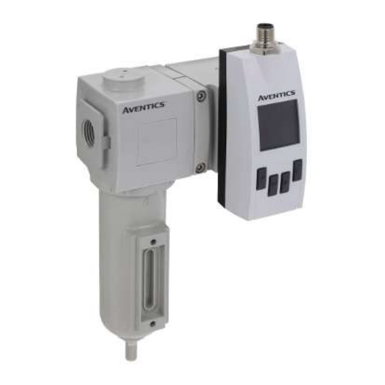
AVENTICS™ 652/653
Durchflusssensor
Flow sensor
Capteur de débit
Flussometro
Sensor de caudal
Flödessensor
Chapitres
Table des Matières

Manuels Connexes pour Emerson AVENTICS 652


Sommaire des Matières pour Emerson AVENTICS 652
- Page 1 Montageanleitung | Assembly instructions | Instructions de montage Istruzioni di montaggio | Instrucciones de montaje | Monteringsanvisning 549411-001-AB 2023-03; Replaces: 2021-05 DE/EN/FR/IT/ES/SV AVENTICS™ 652/653 Durchflusssensor Flow sensor Capteur de débit Flussometro Sensor de caudal Flödessensor...
- Page 34 Sommaire A propos de cette documentation...................................... Validité de la documentation ......................................Documentation supplémentaire ....................................... Abréviations utilisées ........................................Sécurité ............................................. À propos de ce chapitre........................................Utilisation conforme ......................................... Utilisation non conforme ........................................Obligations de l’exploitant ........................................ Qualification du personnel ........................................ Sources de danger ..........................................2.6.1 Risque de blessure......................................
- Page 35 9.1.2 Procédure .......................................... Nettoyage............................................9.2.1 Spécifications générales ..................................... 9.2.2 Procédure .......................................... Maintenance ............................................. Après l’entretien ..........................................10 Démontage et remplacement......................................10.1 Préparation ............................................10.2 Procédure ............................................11 Données et paramètres ........................................11.1 Consignes relatives à la sécurité ......................................11.2 Réglages généraux..........................................11.3 Réglages pour la variante Ethernet IO-Link ..................................
-
Page 36: Propos De Cette Documentation
Remarques 1 A propos de cette documentation • Le produit est destiné à une pose dans des unités de traitement de l’air des sé- Lire entièrement la présente documentation et en particulier le chapitre g 2. Sé- ries 652 et 653 ou comme appareil individuel à l’aide d’équerres de fixation. curité... -
Page 37: Fourniture
• S’assurer que les dernières versions validées du logiciel et du progiciel sont 5.3 Aperçu du produit installées sur tous les produits connectés au réseau. 5.3.1 Versions Type de construction tuyau 652/653 3 Fourniture Type de construction filtre 652 • 1 Instructions de montage •... -
Page 38: Fonctions De Commande Et Éléments De Commande
• Surveillance des fuites dans les conduites d’air comprimé des machines • Mesure des gaz inertes dans le conditionnement des aliments 6 Montage et installation Avant de commencer l’installation : se familiariser le plus tôt possible avec les spécifications de base pour le montage. Voir g 6.1 Planification g 6.2 Prépara- tion. -
Page 39: Remarques
2. Vérifier un éventuel endommagement du produit lié au transport. Procédure Ne pas monter un produit endommagé. Retourner les produits endommagés avec les documents de livraison. Voir g 4.3 Retourner le produit. 3. Préparer les accessoires, le matériel et les outils requis. 6.2.2 Remarques •... -
Page 40: Montage Avec Un Kit De Montage En Batterie
6.3.3 Montage avec un kit de montage en batterie Procédure Selon la variante, le produit est équipé sur sa face supérieure de l’un des raccords suivants pour l’alimentation en tension et les sorties : • Variante IO-Link : Raccord à 5 pôles M12x1. Voir g 6.4.1 Raccord avec connecteur à... -
Page 41: Mise En Service
Tab. 5: Affectation des broches connecteur M12 à 8 pôles 8.2 Configurer le produit Contact RJ45 Couleur des Identification 10/100 Mbit Après raccordement de l’alimentation électrique, le produit peut être configuré. (M12) fils Les détails suivants peuvent être définis : Blanc/orange TX (+) + POE TxData+ •... -
Page 42: Procédure
9.2.2 Procédure Objectif Sous-menu Option 1. Fermer toutes les ouvertures à l’aide de protections appropriées pour empê- Régler l’afficheur 2.1, 2.2 et 2.3 Pages Dans le menu DispHistory, sélection- cher le produit de nettoyage de pénétrer dans le système. ner les paramètres de l’afficheur Optimiser la lisibilité... - Page 43 Objectif Sous-menu Option ScreenSaver Filtre de valeur moyenne pour Flow/Pressure/Temperature Sélectionner l’option Filter et 1 min 2 min l’ajustement de la valeur me- régler le filtre de valeur mesu- 5 min surée sur l’afficheur et la sor- rée 10 min 30 min 60 min Régler le décalage/l’offset du...
- Page 44 Pressure Offset ##.# bar Statistics View max, mean, min values: MassFlowRate abort store Pressure Temperature LastReset Filter VolumetricFlowRate (read only) 100 ms FlowVelocity 200 ms 500 ms abort store Reset (action required) abort store 10 s abort store Fig. 16 Temperature Offset ##.#°C Counter...
-
Page 45: Réglages Pour La Variante Ethernet Io-Link
System Service #_#_#_# Screen 1.1 Screen 2.1 Events Status Signal abort store (Kg/h) Display 1 Top 60 min (m/s) Display 1 Btm (m/s) FactReset (action required) abort store Screen 1.2 Screen 2.2 Info (m³) Display 2 Top Signal Quality SerialNumber (m³/h) Display 2 Btm (read only) Screen 1.3... -
Page 46: Réglages Pour La Variante Ethernet
11.4 Réglages pour la variante Ethernet Q2 Menu Function Switch Frequency Les réglages s’appliquent à toutes les variantes du produit avec le raccord élec- Pulse trique Ethernet. Analog abort store Ethernet Mode Switch Hyst Volumetric Flowrate Objectif Sous-menu Option Switch Hyst Temperature Switch Hyst Pressure Affecter une adresse statique DHCP Mode... -
Page 47: Elimination
OPC UA State Active Send Unit Active Inactive Inactive abort store abort store Port ##### MassFlowRate Active Inactive abort store abort store User # ... # FlowVelocity Active abort store Inactive Password # ... # abort store abort store VolFlowRate Active Inactive Fig. 24... -
Page 48: Erreurs Possibles
Ce chapitre contient un extrait des principales données techniques. D’autres don- spécifiée. nées techniques sont disponibles sur la page dédiée au produit dans l’Emerson Voltage low for Q2/a, Qa Tension à Q2/a, Qa trop basse. Mettre la tension à la valeur Store. -
Page 49: Système Électrique
Des informations relatives aux pièces de rechange figurent sur la page dédiée au Mesure de pression Précision de mesure ≤ ±1,5 % de la plage de mesure produit dans l’Emerson Store. (dans plage 10 ... 30 °C) Non-linéarité ≤ ±0,5 % de la plage de mesure Reproductibilité...