Eurosystems MFL01 Mode D'emploi
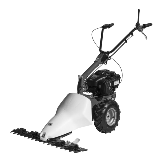
Motofaucheuse

Manuels Connexes pour Eurosystems MFL01


Sommaire des Matières pour Eurosystems MFL01
- Page 7 Hände und Füße von den Schneidwerkzeugen fernhalten! Lesen Sie die Gebrauchsanweisung vor der Aufkleber Gashebel Inbetriebnahme. Non avvicinare mani e piedi agli utensili di taglio Etichetta acceleratore Leggere il manuale prima di usare la macchina. Keep hands and feet away from the blades! Label accelerator Read the instructions manual before operating on N’approchez ni les mains ni les pieds des outils de coupe...
- Page 24 Traduction du mode d’emploi original Introduction Cher client, Table des matières nous vous remercions de la confiance que vous nous témoignez et vous souhaitons beaucoup de satisfaction dans son utilisation. Afin de garantir d’emblée un fonctionnement sans accrocs nous avons créé cette notice d’utilisation. Si Introduction vous observez exactement les indications suivantes votre appareil fonctionnera toujours à...
- Page 25 adolescents de moins de 16 ans ainsi que les personnes sous l’influence de l’alcool, de drogues ou de médicaments ne doivent en aucun cas utiliser l’appareil. 3) La machine a été projetée pour être utilisée par 1 seul opérateur compétent. L’utilisateur de l’appareil répond entièrement des dommages causés à...
-
Page 26: Montage Du Cable De L'accelerateur (Fig.2)
MONTAGE DU CABLE DE L’ACCELERATEUR (Fig.2) Amener le levier (1) installé sur le moteur en fin de course comme indiqué par la flèche « A » sur la figure. Amener la manette de gaz (2) installée sur le mancheron en fin de course comme indiqué par la flèche « B » sur la figure. -
Page 27: Reglage Lateral Du Mancheron (Fig.14)
REGLAGE HAUTEUR BARRE DE COUPE (Fig. 7) Si l’on fauche sur des terrains accidentés, il est nécessaire de régler la hauteur de la barre faucheuse. Effectuer les opérations suivantes : desserrer l’écrou (1) placer le patin (2) dans la position nécessaire, serrer l’écrou (1), Effectuer l’opérations sur les deux patins. -
Page 28: Remplacement De La Lame De Coupe (Fig.12)
meule. Les sections de la lame doivent être affilées avec un angle de 25° degré. REMPLACEMENT DE LA LAME DE COUPE (Fig.12) Lors de l’affûtage ou du remplacement de la lame supérieure, dévisser les vis (1) pour démonter la lame après avoir extrait l’axe du trou (2). Après 2 ou 3 affûtage, il est conseillé de remplacer la lame. Remplacer la lame inférieure selon l’usure, après environ deux remplacement de la lame supérieure. - Page 36 cod. 32.1065.102 06/2020...