
Manuels Connexes pour geo-FENNEL Selection PRO Série


Sommaire des Matières pour geo-FENNEL Selection PRO Série
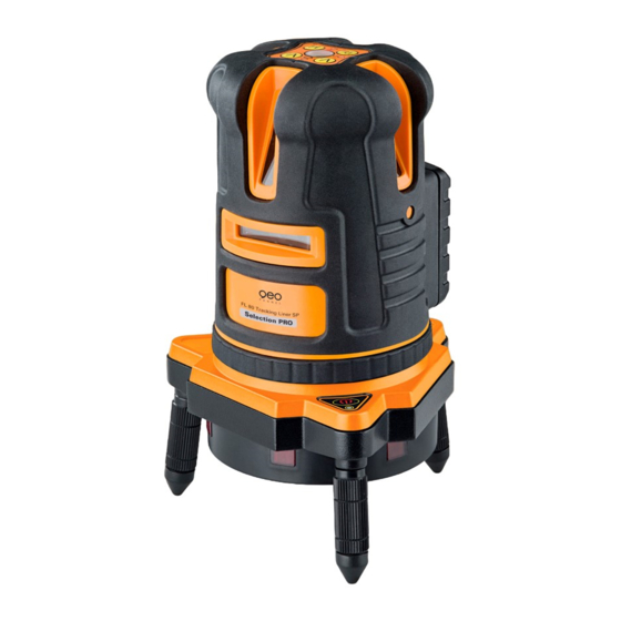
- Page 1 DE | EN | FR FL 80 Tracking Liner SP BEDIENUNGSANLEITUNG USER MANUAL MODE D‘EMPLOI www.geo-fennel.com...
-
Page 2: Table Des Matières
Sehr geehrter Kunde, vielen Dank für das Vertrauen, welches Sie uns beim Erwerb Ihres neuen geo-FENNEL-Gerätes der „Selection Pro“-Reihe entgegengebracht haben. Dieses hochwertige Qualitätsprodukt wurde mit größter Sorgfalt produziert und quali- tätsgeprüft. Im Vergleich zur bisher anerkannten guten Qualität unserer Produkte zeichnet sich die „Selection Pro“-Reihe u.a. -
Page 3: Lieferumfang
Technische Daten Selbstnivellierbereich ± 3° Nivelliergenauigkeit ± 2 mm / 10 m Arbeitsbereich • ohne Empfänger 30 m • mit Empfänger 80 m • Tracking 30 m Zentriergenauigkeit Tracking ±1 mm / 10 m Stromversorgung Li-Ion, Alkaline-Batterien Betriebsdauer Laser 8 Stunden Li-Ion Betriebsdauer Dreifuß... -
Page 4: Bedienelemente
BEDIENELEMENTE Dosenlibelle Bedienfeld Gerät Bedienfeld Gerätefuß AN-/AUS-Schalter und Transportsicherung Laseraustrittsfenster Feinbetrieb Batteriefach 5/8“-Adapter für Stativ justierbare Füße... -
Page 5: Bedienfeld
BEDIENFELD AN/AUS-LED Gerät AN/AUS vertikale Laserlinie V1 AN/AUS vertikale Laserlinie V2 AN/AUS horizontale Laserlinie H Manuell-LED AN/AUS Empfängerfunktion / Manuell-Funktion LED Empfängerfunktion TASTATUR GERÄTEFUSS AN/AUS LED AN/AUS-Taste Dreifuß Beachte: Wenn die AN/AUS-LED blinkt, müssen die Batterien ersetzt werden. -
Page 6: Empfänger Fr-57M
EMPFÄNGER FR-57M 1. Dosenlibelle 2. Empfangsfenster 3. Röhrenlibelle 4. Bedienfeld 5. Anzeige Empfangsstatus 6. Seitliches Bedienfeld 7 . Batteriefach (Rückseite) 8. 1/4“-Gewinde (Rückseite) TASTATUR 1. AN/AUS Ton / Entfernung NAH/WEIT 2. LED Entfernung NAH/WEIT 3. LED AN/AUS 4. AN/AUS Empfänger 5. -
Page 7: Stromversorgung
STROMVERSORGUNG Der Laser kann mit Li-Ion-Akku und alternativ mit handelsüblichen 4 x AA Alkaline- batterien betrieben werden. Li-Ion-Akku Der Laser ist mit einem wiederaufladbaren Li-Ion-Akkupack ausgestattet. Akku- pack in das Gerät einsetzen und mit Schraube des Batteriefachs verschließen. 4 X AA ALKALINE-BATTERIEN Der Laser kann alternativ mit Alkaline-Batterien betrieben werden. -
Page 8: Gerät Aufstellen
BATTERIEN IM GERÄTEFUSS 4 x AA Alkaline-Batterien in die zwei Batteriefächer am Boden des Gerätefußes einlegen (Polarität beachten) und beide Fächer wieder verschließen. LI-ION-AKKU LADEN Ladegerät mit Netz und Ladebuchse am Gerät verbinden. Der Ladezustand wird an der kleinen Lampe am Ladegerät angezeigt: Rotes Licht zeigt an, dass der Akku geladen wird. - Page 9 FEINTRIEB Das Gerät kann grob per Hand oder fein mit dem Feintrieb gedreht werden. HÖHENVERSTELLBARE FÜSSE Gegebenenfalls Dosenlibelle des Bedienfeldes mit Hilfe der 3 höhenverstellbaren Füße des Gerätefußes einspielen, damit die maximale Genauigkeit erreicht wird.
-
Page 10: Gerät Einschalten
GERÄT EINSCHALTEN AN-/AUS-Schalter in Position „ON“ bringen. Das Gerät ist nun betriebsbereit (AN/ AUS-LED leuchtet). Steht das Gerät zu schräg (außerhalb des Selbstnivellierbe- reiches), ertönt ein akustisches Warnsignal. Eingeschaltete Laserlinien blinken als zusätzliche Warnung. Zum Ausschalten AN-/AUS-Schalter wieder in Position „OFF“ stellen. Das Gerät ist nun ausgeschaltet, und der Kompensator wird blockiert, um Beschädigungen während des Transportes zu vermeiden. -
Page 11: Automatische Trackingfunktion
FOLGENDE LASERLINIEN KÖNNEN GESCHALTET WERDEN AUTOMATISCHE TRACKINGFUNKTION (nur möglich bei Vertikallinien) Die automatische Trackingfunktion kann nur in Verbindung mit dem Empfänger FR 57-M genutzt werden. Zur Ausrichtung der Achse: Laser über dem Bodenpunkt aufbauen Nullposition des Empfängers FR 57-M auf den Zielpunkt ausrichten Empfänger FR 57-M aktivieren Die nächstgelegene vertikale Linie fährt exakt auf die Nullposition des Empfän- gers. - Page 12 Taste 1 lang gedrückt halten, um den Ton ein- und auszuschalten. 1 x lang drücken = Ton AN (Bestätigung durch einen Piepton ) 2 x lang drücken = Ton AUS (Bestätigung durch zwei Pieptöne) Taste 1 kurz drücken, um den Empfangsmodus zwischen NAH oder WEIT zu wählen: 1 x kurz drücken = WEIT (Bestätigung durch grüne LED-Anzeige)
-
Page 13: Led Anzeige Und Tonsignale
LED-ANZEIGE UND TONSIGNALE Position Laserlinie LED-Anzeige Tonsignal Sensor vorn einmal kurz Zielpunkt grün lang Sensor gelb zweimal kurz Am Gerätefuß die Power-Taste drücken (LED leuchtet rot) und am Gerät den AN-/ AUS-Schalter (Transportsicherung) auf ON stellen (AN/AUS-LED leuchtet). Nun die gewünschten Vertikallinien schalten (V1, V2) und den Laser auf Emp- fängsmodus AN stellen. - Page 14 Wenn während des Trackingvorgangs eine Pfeiltaste gedrückt wird (rechts oder links), startet der Vorgang von vorn. Beachte: Wenn die Laserlinie bereits das Empfangsfenster des Empfängers erreicht hat und eine Pfeiltaste gedrückt wird, ändert sich die Rotationsrichtung des Geräte- fußes. Zum Energiesparen kann der Gerätefuß nach vollendetem Trackingprozess ausge- schaltet werden.
-
Page 15: Empfängerfunktion Ohne Tracking
EMPFÄNGERFUNKTION OHNE TRACKING Der Empfänger FR 57-M kann horizontal nur manuell verwendet werden, d. h. es erfolgt nur die Höhenanzeige (grüne LED und Dauerton). Horizontal ist keine Trackingfunktion möglich. • Höhenanzeige durch 3-fach LED vorn, hinten und seitlich • Abschaltbarer Ton •... -
Page 16: Sicherheitshinweise
SICHERHEITSHINWEISE PRÜFUNG DER NIVELLIERGENAUIGKEIT Gerät in der Mitte zwischen zwei Wänden aufstellen, die ungefähr 5 m voneinander entfernt sind. Laserkreuz auf Wand markieren. Gerät um 180° drehen und Laserkreuz markieren. Gerät etwa 0,6 m von Wand A aufstellen und Markierungen, wie vorstehend beschrieben, wiederho- len. -
Page 17: Ce-Konformität
Das Gerät entspricht der Lasersicherheitsklasse 2 gemäß der Norm DIN IEC 60825-1:2014. Das Gerät darf ohne weitere Sicherheitsmaßnahmen eingesetzt werden. Das Auge ist bei zufälligem, kurzzei- tigem Hineinsehen in den Laserstrahl durch den Lidschlussreflex geschützt. Laserwarnschilder der Klasse 2 sind gut sichtbar am Gerät angebracht. www.geo-fennel.de G ERMAN Y Laser IEC 60825-1:2014 P ≤... -
Page 18: Garantie
GARANTIE Die Garantiezeit beträgt zwei (2) Jahre, beginnend mit dem Verkaufsdatum. Die Garantie erstreckt sich nur auf Mängel wie Material-oder Herstelungsfehler, sowie die Nichterfüllung zugesicherter Eigenschaften. Ein Garantieanspruch besteht nur bei bestimmungsgemäßer Verwendung. Mecha- nischer Verschleiß und äußerliche Zerstörung durch Gewaltanwendung und Sturz unterliegen nicht der Garantie. - Page 19 NOTIZEN...
- Page 20 Dear customer, Thank you for your confidence having purchased a geo-FENNEL instrument of „Selection Pro“ series. This high-quality product was produced and tested with due prudence. Among others „Selection Pro“ is defined by even clearer visible lines which you are originally used to from our standard range of instruments.
-
Page 21: Supplied With
Technical Specifications self-levelling range ± 3° levelling accuracy ± 2 mm / 10 m working range • with receiver 30 m • without receiver 80 m • Tracking 30 m Centering accuracy Tracking ±1 mm / 10 m Power supply Li-Ion, Alkaline batteries Operating time Laser 8 hours Li-Ion... -
Page 22: Operational Elements
OPERATIONAL ELEMENTS Circular bubble Keypad of instrument Keypad of base ON/OFF knob / transport lock Laser emitting windows Fine adjustment screw Battery compartment 5/8“ thread for tripod Adjustable support leg... -
Page 23: Keypad
KEYPAD ON/OFF vertical laser line V1 ON/OFF LED instrument ON/OFF vertical laser line V2 ON/OFF horizontal laser line H MANUAL LED ON/OFF receiver mode / MANUAL function LED receiver mode KEYPAD BASE 1. ON/OFF LED 2. ON/OFF button tribrach Note: If the ON/OFF LED flashes the batteries must be replaced. -
Page 24: Receiver Fr-57M
RECEIVER FR-57M Circular bubble Receiving window Tube vial Keypad Receiving status indication Side keypad Battery case (back) 1/4“-thread (back) KEYPAD ON/OFF sound / SHORT/LONG distance LED SHORT/LONG distance LED ON/OFF ON/OFF receiver LED Automatic function Automatic function RIGHT LEFT INSERT BATTERIES Put in 3 x AA Alkaline batteries into the battery case (take care to polarity) on the back;... -
Page 25: Power Supply
POWER SUPPLY Both the standard Li-Ion battery or 4 x AA Alkaline batteries can be used. Li-Ion battery pack FL 80 SP comes with Li-Ion rechargeable battery pack. Mount the rechargeable battery box and close the battery compartment with the battery box screw. 4 X AA AKALINE BATTERIES FL 80 SP can be used with Alkaline batteries alternatively. -
Page 26: Set Up The Instrument
BATTERIES OF THE BASE Put in 4 x AA Alkaline batteries into the two Alkaline battery cases on the bottom of the base (take care to polarity) and lock both battery compartments. CHARGE LI-ION BATTERY PACK Connect the charger with the socket. Red light at the charger indicates that batteries are being charged. - Page 27 FINE ADJUSTMENT SCREW The laser can be rotated by hand or carefully by use of the tangent screw. HEIGHT ADJUSTABLE SUPPORT LEGS If necessary centre the circular bubble of the keypad by means of height adjustable support legs in order to reach maximum accuracy.
-
Page 28: Power On The Instrument
POWER ON THE INSTRUMENT Set ON/OFF knob to position „ON“ . The instrument is now ready for use (ON/OFF LED is illuminated). An audible and optical (blinking lines) alarm indicates when the instrument was set up outside of the compensator range. Set up the instru- ment on a more even surface. -
Page 29: Automatic Tracking Function
FOLLOWING LASER LINES CAN BE PROJECTED: AUTOMATIC TRACKING FUNCTION (Available for vertical laser lines only) The automatic tracking function is ony effective together with receiver FR 57-M. For the axis-alignment: Position the laser over the ground point Postion on-grade-mark of receiver FR 57-M at the target point Activate receiver FR 57-M The closest vertical laser line moves to the on-grade-position of the receiver auto- matically... - Page 30 Press button 1 long to switch on or off the signal tone. Press 1 x long for sound ON Confirmation: one beep) Press 2 x long for sound OFF (Confirmation: two beeps) Press button 1 short to select SHORT distance or LONG distance receiving mode Press 1 x short for LONG (Confirmation: green LED indication) Press 2 x short for SHORT...
-
Page 31: Led And Sound Indication
LED AND SOUND INDICATION Position laser line LED indication Sound Sensor front single short Central position green long Sensor yellow twice short Switch on the base by pressing the power button (LED will light red) and the instrument by turning the ON/OFF knob (transport lock) to ON (ON/OFF LED will light red). -
Page 32: Manual Operation
In case one of the arrow buttons (left or right) is used during the tracking procedu- re same will re-start from the beginning. Note: When the laser line is already in the receiving window of the receiver and an arrow button is used the tracking direction of the base will change. In order to save battery power the base can be switched off when the tracking procedure is finished. -
Page 33: Use Of Receiver Without Tracking Function
USE OF RECEIVER WITHOUT TRACKING FUNCTION In horizontal direction the receiver FR 57-M can be used manually, i. e. there is only a height indication (green LED and permanent beep). In horizontal direction the automatic tracking function is not available. Height indication by 3 LEDs which are on the front, side and back Shut-off tone 2-step distance / accuracy mode... -
Page 34: Safety Notes
SAFETY NOTES ACCURACY CHECK Set up instrument in the middle of two walls which are about 5 m apart. Mark visible laser cross on one wall. Turn unit to opposite wall and mark laser cross. Repeat measurements with distance of about 0,6 m to one wall and about 4,4 m to second wall. Deviation between two measurements taken from the centre and two measurements taken at 0,6 m and 4,4 m must not exceed 3 mm. -
Page 35: Safety Instructions
The instrument is a laser class 2 laser product according to DIN IEC 60825-1:2014. It is allowed to use unit without further safety precautions. Eye protection is normally secured by aversion responses and the blink reflex. The laser instrument is marked with class 2 warning labels. www.geo-fennel.de G ERMAN Y Laser IEC 60825-1:2014 P ≤... - Page 36 WARRANTY This product is warranted by the manufacturer to the original purchaser to be free from defects in material and workmanship under normal use for a period of two (2) years from the date of purchase. During the warranty period, and upon proof of purchase, the product will be repaired or replaced (with the same or similar model at manufacturers option), without charge for either parts or labour.
- Page 37 NOTES...
- Page 38 Cher client, Nous tenons à vous remercier pour la confiance que vous nous avez témoignée, par l‘acquisition de votre nouvel instrument geo-FENNEL de la série „Selection Pro“ . Ce produit de qualité de haut de gamme a été fabriqué avec le plus grand soin et vérifié...
-
Page 39: Inclus Dans Le Coffret
Caractéristiques techniques Plage d‘auto nivellement ± 3° Précision ± 2 mm / 10 m Portée • sans cellule 30 m • avec cellule 80 m • en fonction Tracking 30 m Précision en fonction Tracking ±1 mm / 10 m Alimentation Li-Ion, piles d‘Alkaline Autonomie du laser... -
Page 40: Description
DESCRIPTION Nivelle circulaire Clavier d‘instrument Clavier du support Bouton ON/OFF / verouillage pour transport Vitre protection du laser Molette de reglage fin Compartiment piles Filetage 5/8“ Pieds adjustables... -
Page 41: Clavier Du Laser
CLAVIER DU LASER Bouton ON/OFF de la verticale V1 Diode ON/OFF du laser Bouton ON/OFF de la verticale V2 Bouton ON/OFF de l‘horizontale H Diode du mode MANUEL Bouton fonction cellule / mode MANUEL Diode fonction cellule CLAVIER DU SUPPORT 1. -
Page 42: Cellule De Réception Fr 57-M
CELLULE DE RECEPTION FR 57-M Nivelle circulaire Fenêtre de reception Nivelle Clavier Indicateur de positionnement Clavier fonction Tracking Compartiment piles (derriere) Filetage 1/4“ CLAVIER Bouton reglage du son et reglage courte / longue distance reception 2. Diode indication courte / longue 3. -
Page 43: Battérie Et Chargeur
BATTERIE ET CHARGEUR Le laser fonctionne aussi bien sur batterie que sur piles. Pack accus Li Ion Le FL 80 SP est livré avec des battéries rechargeables Li Ion. Placez le pack accu au dos du laser, puis verrouillez le à l‘aide la vis. 4 X AA PILES ALCALINE Le FL 80 SP fonctionne également avec des piles alcalines. -
Page 44: Installation Du Laser
PILES DU SUPPORT Mettre 4x AA piles alcalines dans les compartiments piles prevus à cet effet (at- tention à la polarité) er refermez bien les 2 compartiments. CHARGE DU PACK BATTERIE LI-ION Connectez le chargeur sur la battérie grâce à la fiche. Quand la lumière rouge est allumée, cela signifie que la battérie est en charge. -
Page 45: Molette De Reglage Fin
MOLETTE DE REGLAGE FIN Le laser pivote sur son socle manuellement avec la main ou vous pouvez utiliser la molette sur le côte pour un réglage fin. PIEDS REGLABLES Pour centrer la nivelle dans son cercle, vous pouvez utiliser les pieds réglables pour bénéficier d‘une grande précision de réglage. -
Page 46: Allumer L'appareil
ALLUMER L‘APPAREIL Mettre le bouton en position ON. L ‘instrument est maintenant prêt à être utilisé (la diode ON/OFF doit être allumée). Un signal sonore et lumineux (les lignes clignotent) indique si l‘instrument est en dehors de sa plage de compensation. Si c‘est le cas, placez l‘instrument sur une surface plus plane. -
Page 47: Toutes Les Lignes Ci Dessous Peuvent Être Projeter
TOUTES LES LIGNES CI DESSOUS PEUVENT ÊTRE PROJETER FONCTION TRACKING AUTOMATIQUE (Disponible pour les lignes verticales seulement) La fonction Tracking ne peut fonctionner qu‘avec la cellule FR 57-M. Pour alignement des axes: Positionner le laser sur le pint de référence au sol que vous aveu determiné. Allumer la cellule FR 57-M. - Page 48 Presser le bouton 1 longuement pour allumer le son (1 bip va retentir). Appuyer longuement 2 fois sur le bouton pour éteindre le son (2 bip vont retentir) Presser le bouton 1 brievement pour sélectionner le mode COURTE / LONGUE distance.
-
Page 49: Indication Led Et Son
INDICATION LED ET SON Position ligne laser Indication LED Senseur devant rouge bip court Position centrale vert long Senseur jaune 2 bip court Allumez la base en pressant le bouton ON sur l‘embase (la diode rouge doit s‘allumer) et deverouiller le compensateur en le mettant sur la position ON (la diode ON/OFF doit s‘allumer aussi en rouge). -
Page 50: Mode Manuel
Si on touche aux boutons flèche pendandt la procédure de tracking, alors il faut recommencer la procédure au début. Attention: Quand la ligne laser est déjà alignée sur la fenêtre de réception de la cellule et que l‘on touche aux boutons flèche, le laser va tourner et se décaler d‘une ligne. Attention: Si l‘instrument n‘a pas été... -
Page 51: Utilisation De La Cellule Sans Tracking
UTILITSATION DE LA CELLULE SANS TRACKING En mode horizontal, la cellule FR 57-M ne peut être utilisée qu‘en fonctionnement normale. La fonction tracking ne fonctionnant qu‘en mode vertical. 3 diodes d‘indication de hauteur qui sont devant, sur le côté et derrière la cellule mode silencieux 2 niveaux de réglage de distance et de précision arret automatique... -
Page 52: Notices De Securité
NOTICES DE ESCURITÉ CONTROLLER LA PRÉCISION Poser l‘appareil au milieu de deux murs d‘une distance d‘à peu près 5m. Faire une marque visible sur le mur à l‘endroit où la croix laser est projetée. Tournez l‘appareil à 180° pourvoir si les croix sont bien alignées sur les marques. -
Page 53: Indications D'avertissement Et De Securite
Les pictogrammes de danger de la classe 2 sont bien visibles sur le niveau www.geo-fennel.de G ERMAN Y Laser IEC 60825-1:2014 P ≤... -
Page 54: Exclusion De La Responsabilite
GARANTIE La durée de garantie est de deux (2) ans à partir de la date d‘achat. Cette garantie ne couvre que les défauts tels que le matériel défectueux ou les anomalies de fabrication, ainsi que le manque des propriétés prévues. Le droit à la garantie n‘est valabel que si l‘utilisation du niveau a été conforme aux préscriptions. - Page 55 ANNOTATIONS...
- Page 56 / bloquée entre sol et le plafond Einteilung / graduation / graduation: cm/inch Adapter / adapter / filetage: 5/8“ & 1/4“ für alle geo-FENNEL Laser / for all geo-FENNEL laser / pour Max. Länge / maximal length / longueur max.: 3,40 m tous les lasers geo-FENNEL geo-FENNEL GmbH Technische Änderungen vorbehalten.