
Manuels Connexes pour Tektronix 6 Serie


Sommaire des Matières pour Tektronix 6 Serie
- Page 1 LPD64 6 Series Low Profile Digitizer Installation and Safety Manual *P071365900* 071365900...
- Page 3 LPD64 6 Series Low Profile Digitizer Installation and Safety Manual Supports Product Firmware V1.20.x and above. www.tek.com 071365900...
- Page 4 Tektronix. All rights reserved. Licensed software products are owned by Tektronix or its subsidiaries or suppliers, and are protected by national copyright laws and international treaty provisions. Tektronix products are covered by U.S. and foreign patents, issued and pending. Information in this publication supersedes that in all previously published material. Specifications and price change privileges reserved.
-
Page 5: Table Des Matières
Table of Contents Important safety information ..........................General safety summary ..........................Service safety summary ..........................Terms in the manual ............................Terms on the product ............................ Symbols on the product ..........................Preface ................................Key features ..............................Related documents ............................viii Installing your instrument Check shipped accessories ........................... - Page 6 Table of Contents Maintenance Maintenance ..............................Cleaning ............................... Performance verification interval and adjustment ..................Replaceable parts list ........................... EMC Safety and environmental compliance Compliance Information ..........................EMC compliance ............................ Safety compliance ..........................Environmental compliance ........................LPD64 Installation and Safety Manual...
-
Page 7: Important Safety Information
Connect and disconnect properly. Do not connect or disconnect probes or test leads while they are connected to a voltage source. Use only insulated voltage probes, test leads, and adapters supplied with the product, or indicated by Tektronix to be suitable for the product. - Page 8 WARNING. The product is heavy. To reduce the risk of personal injury or damage to the device get help when lifting or carrying the product. Use only the Tektronix rackmount hardware specified for this product. LPD64 Installation and Safety Manual...
-
Page 9: Service Safety Summary
Important safety information Probes and test leads Before connecting probes or test leads, connect the power cord from the power connector to a properly grounded power outlet. Keep fingers behind the protective barrier, protective finger guard, or tactile indicator on the probes. Remove all probes, test leads and accessories that are not in use. -
Page 10: Terms In The Manual
Important safety information Terms in the manual These terms may appear in this manual: WARNING. Warning statements identify conditions or practices that could result in injury or loss of life. CAUTION. Caution statements identify conditions or practices that could result in damage to this product or other property. Terms on the product These terms may appear on the product: DANGER indicates an injury hazard immediately accessible as you read the marking. -
Page 11: Preface
Preface This manual provides product safety and compliance, how to connect and power on the instrument, and an introduction to the instrument features, controls and basic operations. See the product Help file for more detailed information. Key features Welcome to the 6 Series Low Profile Digitizer LPD64. Low profile instrument with no display, comes ready to install in a 2U rack mount space ■... -
Page 12: Related Documents
To learn about Use this document How to use instrument 6 Series Low Profile Digitizer LPD64 Installation and Safety Manual (this document, Tektronix functions part number 071-3569-xx); standard accessory with the instrument. Single document with English, French, and German languages. -
Page 13: Installing Your Instrument
Installing your instrument Check shipped accessories Make sure that you received everything you ordered. If anything is missing, contact Tektronix Customer Support. In North America, call 1-800-833-9200. Worldwide, visit www.tek.com to find contacts in your area. Check the packing list that came with your instrument to verify that you have received all standard accessories and ordered items. -
Page 14: Power Requirements
To use an Low Profile instrument on a bench, purchase and install the MSO58LP/LPD64 Benchtop Conversion kit (Tektronix part number 020-3180-xx). The kit includes chassis feet and a handle, and lets you stack instruments on a bench. - Page 15 Installing your instrument WARNING. To prevent injury, two people are required to install the instrument. Use two bolts and washers from the supplied hardware to attach one of the rear rack brackets to the rear of the rack. Tighten by hand. Using two people to support the instrument, insert the instrument from the front of the rack so that the chassis rack bracket inserts into the rear rack bracket.
-
Page 16: Secure (Lock) The Instrument
Installing your instrument Secure (lock) the instrument Lock an instrument to a test bench or equipment rack to prevent property loss. Attach a standard laptop security lock to the rear panel of the instrument, to secure the instrument to a workbench, rack, or other location. -
Page 17: Check That The Instrument Passes Power-On Self Tests
If one or more power-on self tests shows Failed: Power cycle the instrument. Tap Utility > Self Test. If one or more power-on self tests still shows Failed, contact Tektronix Customer Support. Connecting signals to the instrument Cables connect the instrument to your device under test (DUT). Use a cable that best matches your signal measurement needs. - Page 18 Installing your instrument LPD64 Installation and Safety Manual...
-
Page 19: Getting Acquainted With Your Instrument
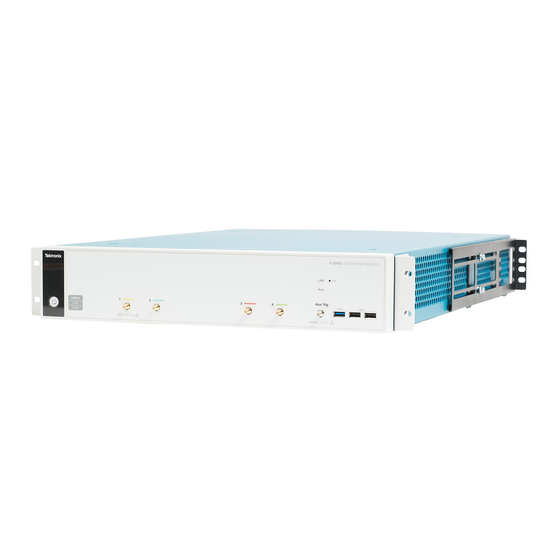
Getting acquainted with your instrument Front panel controls and connections, LPD64 The front panel is where you power on or off the instrument, connect signals with cables, connect an auxiliary trigger input signal, and insert USB devices. The LPD64 front panel Acq status LED: Shows the instrument trigger/acquisition status: Green - Triggered... -
Page 20: Rear Panel Connections
Getting acquainted with your instrument SMA connectors support high bandwidth and frequency cables. Power On/Standby button: Powers the instrument on and off. The power button color indicates instrument power states: No light - No AC power applied ■ Yellow - Standby mode ■... -
Page 21: M.2 Drive Access
Getting acquainted with your instrument M.2 drive access The m.2 solid state drive is easily removable when you need to transport the instrument from a secured facility. The m.2 drive: ■ Contains the system OS ■ Contains all user-related data that was saved to the C: (m.2) drive (waveforms, measurements, settings, and so on) ■... -
Page 22: The Graphical User Interface
Connect a mouse (USB cable) or mouse dongle (for USB wireless mouse) to any USB port. Refer to the 6 Series MSO Installation and Safety Manual (Tektronix part number 071-3579-xx), available to download from www.tek.com/product-support, for details on understanding and using the graphical user interface. -
Page 23: Configure The Instrument
IP address in a web browser. To remotely set a control or run this task on a Low Profile instrument, see the instrument Programmer Manual (Tektronix part number 077-1305-xx) for the correct command or commands to use. -
Page 24: Download And Install The Latest Instrument Firmware
Configure the instrument Download and install the latest instrument firmware Installing the latest firmware helps ensure that your instrument has the lastest features and is taking the most accurate measurements. To access the user interface on a Low Profile instrument, connect a monitor to a video port on the rear of the instrument, and connect a mouse to any USB Host port. -
Page 25: Run Signal Path Compensation (Spc)
If the SPC fails, write down any error message text. Make sure that all probes and cables are disconnected (except for the LPD64) and run the SPC again. If the SPC still fails, contact Tektronix Customer Support. Connect to a network (LAN) Connecting to a network allows you to remotely access the instrument. -
Page 26: Remote Access From A Web Browser (Standard Instrument)
Configure the instrument Obtain or enter the network address information: ■ If your network is DHCP-enabled, and the IP address field does not already show and address, tap Auto to obtain the IP address information from the network. DHCP mode is the default mode. ■... - Page 27 Configure the instrument ® Select Instrument Control (e*Scope ). The browser displays the instrument screen. Use a mouse to select and interact with the instrument controls shown in the Web browser. If your remote PC or laptop has a touch screen monitor, you can use the remote touchscreen monitor to access the instrument controls. NOTE.
- Page 28 Configure the instrument LPD64 Installation and Safety Manual...
-
Page 29: Operating Basics
Operating basics Operating basics Refer to the 6 Series MSO (MSO64) Installation and Safety Manual (Tektronix part number 071-3579-xx) for details on understanding and using the graphical user interface to trigger on and acquire waveforms and take measurements. Refer to the 4/5/6 Series MSO (MSO44, MSO46, MSO54, MSO56, MSO58, MSO58LP, MSO64, LPD64 ) Programmer Manual (Tektronix part number 077-1305-xx) for the correct command or commands to use to remotely operate the instrument. - Page 30 Operating basics LPD64 Installation and Safety Manual...
-
Page 31: Maintenance
If the instrument fails the performance tests in the Specifications and Performance Verification manual, adjustment may be required. Adjustment can only be performed by a Tektronix Service Center. See Contacting Tektronix, following the title page in this manual, for information on contacting Tektronix Service Support. -
Page 32: Replaceable Parts
Maintenance Replaceable parts The following figure shows the user-replaceable parts for the instrument. There are no user-replaceable parts inside the instrument. Figure 4: LPD64 replaceable parts diagram LPD64 Installation and Safety Manual... - Page 33 Maintenance Table 1: Replaceable parts list Index Tektronix part number Name & description number 407-6088-xx BRACKET, FRONT, RACK MOUNT, 2U EAR 211-1682-xx SCREW, 10-32 X 5/16 BUTTON HEAD, CAP, BLACK 407-6089-xx BRACKET, REAR, RACK MOUNT, CHASSIS-SIDE 407-6090-xx BRACKET, REAR, RACK MOUNT, RACK-SIDE...
- Page 34 Maintenance LPD64 Installation and Safety Manual...
-
Page 35: Emc Safety And Environmental Compliance
This product is intended for use by professionals and trained personnel only; it is not designed for use in households or by children. Questions about the following compliance information may be directed to the following address: Tektronix, Inc. PO Box 500, MS 19-045 Beaverton, OR 97077, USA www.tek.com... -
Page 36: Safety Compliance
EMC Safety and environmental compliance EMC Compliance Meets the intent of Directive 2014/30/EU for Electromagnetic Compatibility when it is used with the product(s) stated in the specifications table. Refer to the EMC specification published for the stated products. May not meet the intent of the directive if used with other products. -
Page 37: Environmental Compliance
EMC Safety and environmental compliance Safety class Class I -- grounded product. Pollution degree description A measure of the contaminants that could occur in the environment around and within a product. Typically the internal environment inside a product is considered to be the same as the external. Products should be used only in the environment for which they are rated. -
Page 38: Battery Recycling
This symbol indicates that this product complies with the applicable European Union requirements according to Directives 2012/19/EU and 2006/66/EC on waste electrical and electronic equipment (WEEE) and batteries. For information about recycling options, check the Tektronix Web site (www.tek.com/productrecycling). Battery recycling This product contains a small installed lithium metal button cell. - Page 39 Index ACQ acquisition status LED, 7 AFG Out (rear panel), 8 LAN port (rear panel), 8 AUX Out (rear panel), 8 LAN status LEDs, 7 Aux Trig trigger input, 7 LAN, connect to, 13 lock to bench or rack, 4 cable lock, 8 clock format (12/24 hr), how to set, 11 Maintenance...
- Page 40 Index power cord, 8 security cable lock, 8 clock format (12/24 hr), 11 USB Device port, 8 time zone, 11 signal input levels, 2 USB Host ports, 8 SPC (signal path compensation), 13 video output, 8 rear panel connections, 8 standard accessories, 1 Ref In, 8 Ref In (rear panel), 8...
- Page 41 LPD64 Numériseur profil bas Série 6 Manuel d’installation et de sécurité *P071365900* 071365900...
- Page 43 LPD64 Numériseur profil bas Série 6 Manuel d’installation et de sécurité Prise en charge du firmware produit V1.20.x et ultérieures www.tek.com 071365900...
-
Page 44: Prendre Contact Avec Tektronix
Tektronix. Tous droits réservés. Les produits logiciels sous licence sont la propriété de Tektronix, de ses filiales ou de ses fournisseurs et sont protégés par les lois nationales sur le copyright, ainsi que par des traités internationaux. Les produits Tektronix sont protégés par des brevets américains et étrangers déjà... - Page 45 Sommaire Informations importantes relatives à la sécurité ....................Consignes générales de sécurité ........................Consignes générales de maintenance ......................Termes utilisés dans le manuel ........................Mentions figurant sur le produit ........................Symboles figurant sur le produit ........................Préface ................................Principales fonctionnalités ..........................
- Page 46 Sommaire Chapitre 5: Maintenance Maintenance ..............................Nettoyage ..............................Réglage et fréquence de vérification des performances ................Liste des pièces de rechange ........................Chapitre 6: Conformité environnementale et sécurité CEM Informations relatives à la conformité ......................Conformité CEM ............................. Conformité en matière de sécurité ......................
-
Page 47: Informations Importantes Relatives À La Sécurité
à une source de tension.Utilisez uniquement les sondes de tension isolées, les fils de test et les adaptateurs fournis avec le produit ou recommandés par Tektronix et adaptés au produit. Manuel d’installation et de sécurité du numériseur LPD64... - Page 48 Informations importantes relatives à la sécurité Respectez toutes les caractéristiques nominales des bornes.. Pour éviter tout risque d'incendie ou d'électrocution, respectez toutes les caractéristiques nominales et les marquages du produit. Avant de brancher le produit, consultez le manuel fourni pour obtenir les caractéristiques nominales.
- Page 49 AVERTISSEMENT. Ce produit est lourd. Pour réduire les risques de blessure ou de détérioration de l'appareil, faites-vous aider lorsque vous levez ou portez le produit. Utilisez uniquement le rack Tektronix prévu pour ce produit. Sondes et cordons de test Avant de connecter des sondes ou des cordons de test, branchez le cordon d'alimentation sur une prise correctement reliée à la terre.
-
Page 50: Avertissements Et Informations Relatifs À L'évaluation Du Risque
Informations importantes relatives à la sécurité Avertissements et informations relatifs à l’évaluation du risque Consignes générales de maintenance Le paragraphe Consignes générales de maintenance contient les informations nécessaires à l'entretien de ce produit. Seul un personnel qualifié doit effectuer les opérations d'entretien. Lisez attentivement ce paragrapheet le paragraphe Consignes générales de sécurité... -
Page 51: Symboles Figurant Sur Le Produit
Informations importantes relatives à la sécurité Symboles figurant sur le produit Lorsque ce symbole est apposé sur le produit, consultez le manuel pour rechercher la nature des dangers potentiels et les mesures à prendre pour les éviter. (Ce symbole peut également être utilisé pour indiquer à l'utilisateur les caractéristiques nominales figurant dans le manuel.) Les symboles suivants peuvent être présents sur le produit : Manuel d’installation et de sécurité... - Page 52 Informations importantes relatives à la sécurité viii Manuel d’installation et de sécurité du numériseur LPD64...
-
Page 53: Préface
Préface Le présent manuel contient des informations sur la conformité et la sécurité du produit, des instructions pour la connexion et la mise sous tension, ainsi qu’une présentation des principales commandes et fonctions de l’instrument. Reportez-vous au fichier d’aide de l’instrument pour obtenir des informations plus détaillées. Principales fonctionnalités Numériseur à... -
Page 54: Documentation Connexe
Tektronix 071-3569-xx) ; accessoire standard avec l’instrument. Document unique disponible en anglais, français et allemand. Aide MSO Série 4/5/6 (référence Tektronix 077-1303-xx ; version imprimable de l’aide de l’instrument ; disponible sur www.tek.com/downloads) Contrôle à distance de Manuel de programmation MSO Série 4/5/6 (référence Tektronix 077-1305-xx ; disponible sur l’instrument... -
Page 55: Chapitre 1: Installation De L'instrument
Assurez-vous d’avoir reçu tous les articles que vous avez commandés. S’il manque un ou plusieurs articles, prenez contact avec l’assistance clientèle Tektronix. En Amérique du Nord, appelez le 1-800-833-9200. Pour les autres pays, visitez le site www.tek.com pour connaître les coordonnées locales. -
Page 56: Puissance Requise
Si vous souhaitez utiliser un instrument à profil bas sur un plan de travail, achetez le Kit de conversion pour table de travail MSO58LP/LPD64 (référence Tektronix 020-3180-xx). Ce kit contient des pieds pour le châssis et une poignée, afin d’empiler les instruments sur la table de travail. - Page 57 Installation de l’instrument AVERTISSEMENT. Pour éviter toute blessure, prévoyez deux personnes pour installer l’instrument. Utilisez deux boulons et rondelles fournis avec l’instrument pour fixer l’un des crochets de celui-ci aux supports situés sur l’arrière de la baie. Serrez à la main. En portant l’instrument à...
-
Page 58: Verrouillage De L'instrument
Installation de l’instrument Verrouillage de l’instrument Fixez l’instrument sur un banc d’essai ou une baie de montage à l’aide d’un câble de sécurité, pour éviter les vols. Fixez un câble de sécurité standard pour ordinateur portable sur le panneau arrière de l’instrument, afin de fixer l’instrument à un banc d’essai, à... -
Page 59: Vérifiez Que L'instrument Réussit Les Auto-Tests À La Mise Sous Tension
éteignez, puis rallumez l’instrument. Appuyez sur Utility (Utilitaire) > Self Test (Auto-test). Si un ou plusieurs auto-tests indiquent encore Failed (Echec), prenez contact avec l’assistance clientèle Tektronix. Connexion de signaux sur l’instrument Les câbles permettent de raccorder l’instrument à l’appareil testé. Utilisez une câble adapté(e) à vos besoins en matière de mesure du signal. - Page 60 Installation de l’instrument Manuel d’installation et de sécurité du numériseur LPD64...
-
Page 61: Chapitre 2: Présentation De L'instrument
Présentation de l’instrument Commandes et connecteurs de la face avant, LPD64 Les commandes et connecteurs de la face avant vous permettent de mettre l’instrument sous et hors tension, de connecter des signaux à l’aide de câbles, de connecter un signal d’entrée de déclenchement auxiliaire et de brancher des périphériques USB. Face avant du LPD64 LED d’état d’acquisition : indique le statut d’acquisition/de déclenchement de l’instrument :... -
Page 62: Connecteurs Du Panneau Arrière
Présentation de l’instrument ces connecteurs prennent en charge des câbles de fréquence et de bande passante supérieurs. Bouton de mise en marche/mise en veille : permet de mettre en marche et d’arrêter l’instrument. La couleur du bouton Marche/Arrêt indique l’état de l’instrument. Éteint : l’instrument n’est pas alimenté. -
Page 63: Accès Au Disque M.2
Présentation de l’instrument Accès au disque m.2 Vous pouvez facilement retirer le disque SSD m.2 lorsque vous avez besoin de transporter l’instrument vers un lieu non sécurisé. Le disque m.2 : • contient le système d’exploitation de l’instrument ; • contient toutes les données relatives à... -
Page 64: Interface Utilisateur Graphique
Branchez une souris (souris filaire) ou dongle pour souris (souris sans fil) sur le port USB de votre choix. Reportez-vous au Manuel d’installation et de sécurité MSO Série 6 (référence Tektronix 071-3579-xx), disponible au téléchargement sur le site www.tek.com/product-support, pour plus d’informations sur l’interface utilisateur graphique et son utilisation. -
Page 65: Chapitre 3: Configuration De L'instrument
Pour configurer les commandes ou exécuter cette tâche à distance sur un instrument à profil bas, reportez-vous au Manuel de programmation de l’instrument (référence Tektronix 077-1305-xx) pour connaître la ou les commandes à utiliser. Réglage du fuseau horaire et du format d’horloge Spécifiez le fuseau horaire de votre région afin que les fichiers enregistrés soient correctement horodatés. -
Page 66: Téléchargement Et Installation De La Version La Plus Récente Du Firmware De L'instrument
Configuration de l’instrument Téléchargement et installation de la version la plus récente du firmware de l’instrument Installer la dernière version du firmware vous permet de bénéficier des fonctionnalités les plus récentes, pour des mesures à la précision toujours optimale. Pour accéder à l’interface utilisateur sur un instrument à profil bas, branchez un moniteur sur l’un des ports vidéo situés à l’arrière de l’instrument, puis branchez une souris sur l’un des ports USB hôte. -
Page 67: Compensation Du Chemin Du Signal (Spc)
Si la SPC échoue, notez le texte du message d’erreur qui s’affiche. Assurez-vous que toutes les sondes et tous les câbles sont débranchés (excepté dans le cas du numériseur LPD64) avant de relancer la SPC. Si la SPC échoue à nouveau, prenez contact avec l’assistance clientèle Tektronix. Manuel d’installation et de sécurité du numériseur LPD64... -
Page 68: Connexion À Un Réseau Local (Lan)
Configuration de l’instrument Connexion à un réseau local (LAN) Connecter l’instrument à un réseau vous permet d’y accéder à distance. Pour accéder à l’interface utilisateur sur un instrument à profil bas, branchez un moniteur sur l’un des ports vidéo situés à l’arrière de l’instrument, puis branchez une souris sur l’un des ports USB hôte. - Page 69 Configuration de l’instrument ® Sélectionnez Instrument Control (Contrôle d’instrument) (e*Scope ). Le navigateur affiche l’écran de l’instrument. Servez-vous de la souris pour sélectionner et utiliser les commandes de l’instrument affichées dans le navigateur Web. Si votre PC ou ordinateur portable distant dispose d’un écran tactile, vous pouvez l’utiliser pour accéder aux commandes de l’instrument.
- Page 70 Configuration de l’instrument Manuel d’installation et de sécurité du numériseur LPD64...
-
Page 71: Chapitre 4: Principes De Fonctionnement
Reportez-vous au Manuel de programmation MSO Série 4/5/6 (MSO44, MSO46, MSO54, MSO56, MSO58, MSO58LP, MSO64, LPD64 ) (référence Tektronix 077-1305-xx) afin de connaître la ou les commandes adéquates à utiliser pour faire fonctionner l’instrument à distance. - Page 72 Principes de fonctionnement Manuel d’installation et de sécurité du numériseur LPD64...
-
Page 73: Chapitre 5: Maintenance
Le réglage peut être effectué uniquement par un centre de maintenance Tektronix. Consultez la rubrique Contacter Tektronix après la page de titre dans ce manuel pour obtenir des informations ou rapprochez-vous du service clientèle de Tektronix. -
Page 74: Liste Des Pièces De Rechange
Maintenance Liste des pièces de rechange Cette section contient des informations sur les pièces de rechange pour votre instrument. Utilisez les listes de la section appropriée pour identifier et commander des pièces de rechange pour votre produit. Accessoires standard Les accessoires standard pour ces produits sont répertoriés au début du présent manuel. Pièces de rechange La figure suivante illustre les pièces de rechange que l’utilisateur peut remplacer lui-même sur son instrument. - Page 75 Maintenance Table 1: Liste des pièces de rechange Numéro Référence Tektronix Quantité Désignation et description d’index 407-6088-xx SUPPORT, AVANT, MONTAGE SUR BAIE, OREILLE 2U 211-1682-xx VIS, 10-32 X 5/16 TÊTE BOMBÉE, CACHE, NOIRE 407-6089-xx SUPPORT, ARRIÈRE, MONTAGE SUR BAIE, CÔTÉ CHÂSSIS 407-6090-xx SUPPORT, ARRIÈRE, MONTAGE SUR BAIE, CÔTÉ...
- Page 76 Maintenance Manuel d’installation et de sécurité du numériseur LPD64...
-
Page 77: Chapitre 6: Conformité Environnementale Et Sécurité Cem
être utilisé en environnement domestique ou par des enfants. Les questions relatives aux informations sur la conformité ci-dessous doivent être directement posées à l’adresse suivante : Tektronix, Inc. PO Box 500, MS 19-045 Beaverton, OR 97077, États-Unis www.tek.com... -
Page 78: Conformité En Matière De Sécurité
Conformité environnementale et sécurité CEM Conformité CEM Conforme à la Directive 2014/30/CE sur la compatibilité électromagnétique lorsque le produit est utilisé avec les produits mentionnés dans les spécifications. Voir les spécifications CEM publiées pour les produits indiqués. L'appareil ne sera peut-être pas conforme à... - Page 79 Conformité environnementale et sécurité CEM Type d'équipement Équipement de mesure et de test. Classe de sécurité Classe I – Produit raccordé à la terre. Description des niveaux de pollution Mesure des contaminants pouvant se trouver dans l'environnement autour et à l'intérieur du produit. L'environnement intérieur d'un produit est généralement considéré...
-
Page 80: Conformité Environnementale
Ce symbole indique que ce produit respecte les exigences applicables de l'Union européenne, conformément aux directives 2012/19/CE et 2006/66/UE relatives aux déchets d'équipements électriques et électroniques (DEEE), et aux batteries. Pour en savoir plus sur les options de recyclage, consultez le site web de Tektronix (www.tek.com/productrecycling). - Page 81 L'index accès à distance (connexion Web), 14 firmware, procédure de mise à jour, 12 accès à distance (e*Scope), 14 fixation de sécurité sur banc d’essai ou sur baie, 4 accessoires standard, 1 fonctionnement attache pour câble, 8 plage d’altitude, 1, 2 attache pour câble de sécurité, 8 plage d’humidité, 1, 2 plage de température, 1, 2...
- Page 82 L'index port de périphérique USB (panneau arrière), 8 Port Ethernet (panneau arrière), 8 Port LAN (panneau arrière), 8 réglage Ports hôte USB (panneau arrière), 8 format horaire (12/24 h), 11 procédure fuseau horaire, 11 accès à l’instrument à distance (connexion Web), 14 réseau, connexion, 14 compensation du chemin du signal (SPC), 13 résultats de l’auto-test, 5...
- Page 83 LPD64 Niedrigprofil-Digitalisierer der Serie 6 Installations- und Sicherheitshandbuch * P 071365900* 071365900...
- Page 85 LPD64 Niedrigprofil-Digitalisierer der Serie 6 Installations- und Sicherheitshandbuch Unterstützt Firmware V1.20.x und höher www.tek.com 071365900...
- Page 86 Zulieferern des Unternehmens dar und sind durch das nationale Urheberrecht und die Bestimmungen internationaler Verträge geschützt. Tektronix-Produkte sind durch erteilte und angemeldete Patente in den USA und anderen Ländern geschützt. Die Informationen in dieser Broschüre ersetzen alle einschlägigen Angaben älterer Unterlagen. Änderungen der Spezifikationen und der Preisgestaltung vorbehalten.
- Page 87 Inhalt Wichtige Sicherheitsinformationen ........................Allgemeine Sicherheitshinweise ........................Sicherheit bei Wartungsarbeiten ........................In diesem Handbuch verwendete Begriffe ..................... Am Gerät verwendete Begriffe ........................Symbole am Gerät ............................Vorwort ................................Hauptfunktionen ............................Weiterführende Dokumente ........................... 1: Installieren des Geräts Geliefertes Zubehör überprüfen ........................
- Page 88 Inhalt 5: Wartung Wartung ................................ Reinigung ..............................Leistungsprüfungsintervall und -einstellung ....................Ersatzteilliste ..............................6: Einhaltung der EMV-Sicherheits- und Umweltschutzbestimmungen Informationen zur Konformität ........................EMV-Konformität ............................ Einhaltung von Sicherheitsbestimmungen ..................... Einhaltung von Umweltschutzbestimmungen ..................LPD64 Installations- und Sicherheitshandbuch...
-
Page 89: Wichtige Sicherheitsinformationen
Spannungsquelle angeschlossen sind.Verwenden Sie nur isolierte Spannungstastköpfe, Prüfleitungen und Adapter, die mit dem Produkt geliefert wurden oder die von Tektronix als geeignetes Zubehör für die Produkte genannt werden. Alle Angaben zu den Anschlüssen beachten. Beachten Sie zur Verhütung von Bränden oder Stromschlägen die Kenndatenangaben und Kennzeichnungen am Gerät. - Page 90 Wichtige Sicherheitsinformationen Schließen Sie keine Spannung an Klemmen – einschließlich Masseanschlussklemmen – an, die den maximalen Nennwert der Klemme überschreitet. An der Masseanschlussklemme dürfen keine potenzialfreien Messungen vorgenommen werden, deren Werte die für diese Klemme angegebene Nennspannung übersteigen. Die Messanschlussklemmen an diesem Gerät sind nicht für den Anschluss an ein Stromnetz oder an Stromkreise der Überspannungskategorien II, III oder IV vorgesehen.
- Page 91 Wichtige Sicherheitsinformationen Verwenden Sie für den Gestelleinbau ausschließlich die von Tektronix für dieses Gerät vorgegebene Hardware. Tastköpfe und Prüfleitungen Bevor Sie Tastköpfe oder Prüfleitungen anschließen, müssen Sie zunächst das vom Netzanschluss des Geräts abgehende Netzkabel an eine ordnungsgemäß geerdete Steckdose anschließen.
-
Page 92: Sicherheit Bei Wartungsarbeiten
Wichtige Sicherheitsinformationen Warnhinweise und Informationen zur Risikobewertung Sicherheit bei Wartungsarbeiten Der Abschnitt Sicherheit bei Wartungsarbeiten enthält zusätzliche Informationen, die für eine sichere Wartung des Gerätes relevant sind. Wartungsarbeiten sind nur von qualifiziertem Personal durchzuführen. Bevor Sie Wartungsmaßnahmen gleich welcher Art durchführen, sollten Sie sich die Angaben unter Sicherheit bei Wartungsarbeiten sowie die Allgemeinen Sicherheitshinweisen durchlesen. -
Page 93: Symbole Am Gerät
Wichtige Sicherheitsinformationen Symbole am Gerät Ist das Gerät mit diesem Symbol gekennzeichnet, lesen Sie unbedingt im Handbuch nach, welcher Art die potenziellen Gefahren sind und welche Maßnahmen zur Vermeidung derselben zu treffen sind. (In einigen Fällen wird das Symbol aber auch verwendet, um den Benutzer darauf hinzuweisen, dass im Handbuch Kennwerte zu finden sind.) Am Gerät sind eventuell die folgenden Symbole zu sehen: LPD64 Installations- und Sicherheitshandbuch... - Page 94 Wichtige Sicherheitsinformationen viii LPD64 Installations- und Sicherheitshandbuch...
-
Page 95: Vorwort
Vorwort Dieses Handbuch enthält Informationen zu Produktkonformität und -sicherheit, zum Anschluss und Starten des Geräts sowie eine Einführung in Funktionen, Bedienelemente und grundlegende Vorgehensweisen des Geräts. Siehe die Hilfe-Datei des Produktes für nähere Informationen. Hauptfunktionen Willkommen zum Niedrigprofil-Digitalisierer LPD64 der Serie 6. Das Niedrigprofil-Gerät ohne Anzeige wird installationsbereit in einem 2HE-Rackmontagekit geliefert. - Page 96 Gerätefunktionen an? Dokument, Tektronix Bestellnummer 071-3569-xx); Standard-Gerätezubehör. Einzeldokument auf Englisch, Französisch und Deutsch. Hilfe für MSO-Dokumente der Serie 4/5/6 (Tektronix Bestellnummer 077-1303-xx; Druckversion der Hilfe des Geräts; verfügbar unter www.tek.com/downloads) Wie lässt sich das Gerät Programmierhandbuch für MSO-Geräte der Serie 4/5/6 (Tektronix Bestellnummer 077-1305-xx;...
-
Page 97: 1: Installieren Des Geräts
Installieren des Geräts Geliefertes Zubehör überprüfen Stellen Sie sicher, dass Sie Ihre komplette Bestellung erhalten haben. Sollte etwas fehlen, kontaktieren Sie bitte den Tektronix- Kundenservice. Diesen erreichen Sie in Nordamerika unter der Rufnummer 1-800-833-9200. Unter www.tek.com finden Sie Ansprechpartner in Ihrer Nähe. -
Page 98: Anforderungen An Die Stromversorgung
Unterlegscheiben aus dem Beutel, der mit dem Gerät mitgeliefert wurde, um die hinteren Halterungen im Rack zu installieren. Um das Niedrigprofil-Gerät auf einer Werkbank nutzen zu können, kaufen und installieren Sie das MSO58LP/LPD64 Werkbank- Anpassungs-Kit (Tektronix Bestellnummer 020-3180-xx). Dieses Kit umfasst Abstellfüße und einen Griff und ermöglicht ein Stapeln der Geräte auf einer Werkbank. - Page 99 Installieren des Geräts WARNUNG. Um Verletzungen auszuschließen, sollte das Gerät mithilfe von zwei weiteren Personen installiert werden. Verwenden Sie zwei Schrauben und Unterlegscheiben der mitgelieferten Bauteile, um eine der hinteren Halterungen an der Rückwand des Racks zu befestigen. Ziehen Sie die Schrauben von Hand an. Zwei Personen sollten das Gerät festhalten, während Sie das Gerät an der Vorderseite des Racks einführen, sodass die Gehäuse-Halterung in die hintere Halterung des Racks einrastet.
-
Page 100: Sichern (Sperren) Des Geräts
Installieren des Geräts Sichern (Sperren) des Geräts Verriegeln Sie ein Gerät auf einer Werkbank oder in einem Geräte-Rack, um zu verhindern, dass es abhandenkommt. Bringen Sie das Laptop-Standardsicherheitsschloss an der Rückwand des Geräts an, um das Gerät auf einer Werkbank, in einem Rack oder an anderweitigen Orten zu sichern. -
Page 101: Überprüfung Der Durchführung Von Selbsttests Beim Start
Schalten Sie das Gerät aus und wieder ein. Tippen Sie auf Utility > Self Test (Dienstprogramm > Selbsttest). Weist das Gerät selbst nach mehreren Versuchen weiterhin den Status Failed (Nicht bestanden) auf, kontaktieren Sie den Tektronix-Kundendienst. Anschließen von Signalen an das Gerät Kabel verbinden das Gerät mit Ihrem Testgerät (DUT). - Page 102 Installieren des Geräts LPD64 Installations- und Sicherheitshandbuch...
-
Page 103: 2: Umgang Mit Dem Gerät
Umgang mit dem Gerät Anschlüsse und Bedienelemente an der Frontplatte, LPD64 Die Frontplatte ist der Bereich, in dem Sie das Gerät ein- oder ausschalten, Signale mit Kabeln verbinden, ein zusätzliches Trigger-Eingangssignal anschließen und USB-Geräte einstecken können. LPD64 Frontplatte Acq Status-LED: Zeigt den Trigger-/Erfassungsstatus des Geräts an: Grün - Getriggert •... -
Page 104: Anschlüsse An Der Rückwand
Umgang mit dem Gerät SMA-Steckverbinder unterstützen hohe Bandbreiten und Hochfrequenzkabel. Ein/Aus-/Standby-Taste: Schaltet das Gerät ein und aus. Die Farbe der Startschaltfläche des Geräts informiert über den Stromversorgungsstatus: Leuchtet nicht auf – Keine Wechselspannung • Gelb – Standby-Modus • Blau – Eingeschaltet •... -
Page 105: Zugang Zum M.2-Laufwerk
Umgang mit dem Gerät Zugang zum M.2-Laufwerk Das M.2 Solid-State-Laufwerk kann einfach entnommen werden, wenn Sie das Instrument aus einer gesicherten Einrichtung abtransportiert werden muss. Das M.2-Laufwerk: • Enthält das Betriebssystem. • Enthält benutzerrelevante Daten, die auf dem C: (M.2)-Laufwerk gespeichert wurden (Signale, Messungen, Einstellungen usw.). -
Page 106: Die Grafische Benutzeroberfläche
Schließen Sie eine Maus (USB-Kabel) oder einen Maus-Dongle (für drahtlose USB-Maus) an eine USB-Buchse an. Siehe das Installations- und Sicherheitshandbuch für MSO-Geräte der Serie 6 (Tektronix Bestellnummer 071-3579-xx), das unter www.tek.com/product-support heruntergeladen werden kann, für nähere Informationen zu Verständnis und Nutzung der grafischen Benutzeroberfläche. -
Page 107: 3: Konfiguration Des Geräts
Gerät einrichten, indem die IP-Adresse des Geräts in einen Webbrowser eingegeben wird. Für die Ferneinstellung der Bedienelemente oder die Ausführung dieser Funktion auf einem Niedrigprofil-Gerät siehe die Programmieranleitung des Geräts (Tektronix Bestellnummer 077-1305-xx), um die richtige Steuerung und Bedienung des Geräts sicherzustellen. -
Page 108: Laden Sie Die Aktuellste Firmware Herunter Und Installieren Sie Sie
Konfiguration des Geräts Laden Sie die aktuellste Firmware herunter und installieren Sie sie. Durch Installation der aktuellsten Firmware-Version wird sichergestellt, dass Ihr Gerät mit den aktuellsten Funktionen ausgestattet ist und genaueste Messungen durchführen kann. Um bei einem Niedrigprofil-Gerät auf die Benutzeroberfläche zuzugreifen, schließen Sie einen Monitor an eine Videobuchse an der Rückwand des Geräts und eine Maus an einen USB-Host-Anschluss an. -
Page 109: Ausführung Der Signalpfadkompensation (Spc)
Schließen Sie den Konfigurationsdialog der Kalibrierung, wenn die SPC erfolgreich durchgeführt wurde. Wenn die SPC fehlschlägt, notieren Sie den Wortlaut der Fehlermeldung(en). Stellen Sie sicher, dass alle Tastköpfe und Kabelverbindungen ausgesteckt wurden (außer bei LPD64) und führen Sie die SPC erneut aus. Kontaktieren Sie Tektronix- Kundenservice, wenn die SPC weiterhin fehlschlägt. -
Page 110: Verbindung Zu Einem Netzwerk (Lan) Herstellen
Konfiguration des Geräts Verbindung zu einem Netzwerk (LAN) herstellen Über eine Netzwerkverbindung haben Sie die Möglichkeit, das Gerät fernzusteuern. Um bei einem Niedrigprofil-Gerät auf die Benutzeroberfläche zuzugreifen, schließen Sie einen Monitor an eine Videobuchse an der Rückwand des Geräts und eine Maus an einen USB-Host-Anschluss an. Sie müssen keine Maus anschließen, wenn der Fernmonitor touchfähig ist. - Page 111 Konfiguration des Geräts ® Wählen Sie Instrument Control (Gerätesteuerung) (e*Scope ). Im Browser wird der Gerätebildschirm angezeigt. Verwenden Sie eine Maus, um die Steuerelemente des Geräts, die im Webbrowser angezeigt werden, auszuwählen und mit ihnen zu interagieren. Wenn Ihr Remote-PC oder -Laptop über einen Touchscreen verfügt, können Sie diesen für den Fernzugriff auf die Steuerelemente des Geräts verwenden.
- Page 112 Konfiguration des Geräts LPD64 Installations- und Sicherheitshandbuch...
-
Page 113: 4: Grundlegende Bedienung Des Geräts
Messungsdurchführung. Siehe die Programmieranleitung für MSO-Geräte der Serie 4/5/6 (MSO44, MSO46, MSO54, MSO56, MSO58, MSO58LP, MSO64, LPD64) (Tektronix Bestellnummer 077-1305-xx) für die korrekte Steuerung der Befehle zur Fernbedienung des Geräts. Beide Handbücher können unter www.tek.com/product-support heruntergeladen werden. LPD64 Installations- und Sicherheitshandbuch... - Page 114 Grundlegende Bedienung des Geräts LPD64 Installations- und Sicherheitshandbuch...
-
Page 115: Wartung
In diesem Abschnitt finden Sie Informationen zur regelmäßigen Durchführung von Wartungsarbeiten am Gerät. VORSICHT. Nehmen Sie die Abdeckung des Geräts nicht ab, außer wenn diese beschädigt ist und ersetzt werden muss. Es gibt keine austauschbaren Bauteile im Gerät. Senden Sie das Gerät an Tektronix zurück, wenn es gewartet werden muss. Reinigung Verwenden Sie zur Reinigung der Geräteaußenseite ein trockenes weiches Baumwolltuch. -
Page 116: Ersatzteilliste
Wartung Ersatzteilliste In diesem Abschnitt finden Sie Informationen über austauschbare Bauteile des Gerätes. Anhand der Listen im jeweiligen Abschnitt können Sie die Bauteile erkennen und Ersatzteile bestellen. Standardzubehör Standardzubehör für diese Produkte finden Sie zu Beginn des Benutzerhandbuchs. Ersatzteile Folgende Abbildung zeigt vom Benutzer austauschbare Bauteile für das Gerät. Es gibt keine austauschbaren Bauteile im Gerät. Abbildung 4: LPD64 Ersatzteildiagramm LPD64 Installations- und Sicherheitshandbuch... - Page 117 Wartung Tabelle 1: Ersatzteilliste Indexnumm Tektronix-Bestellnummer Menge Bezeichnung & Beschreibung 407-6088-xx HALTERUNG, FRONTPLATTE, RACKMONTAGE, 2 HE WINKEL 211-1682-xx SCHRAUBE, 10-32 X 5/16 HALBRUNDKOPF, KAPPE, SCHWARZ 407-6089-xx HALTERUNG, RÜCKWAND, RACKMONTAGE, GEHÄUSESEITE 407-6090-xx HALTERUNG, RÜCKWAND, RACKMONTAGE, RACKSEITE 020-3180-xx WERKBANK-ANPASSUNGSKIT (optionales Zubehör) Nicht dargestellt: Netzstecker für Nordamerika (115 V, 60 Hz)
- Page 118 Wartung LPD64 Installations- und Sicherheitshandbuch...
-
Page 119: 6: Einhaltung Der Emv-Sicherheits- Und Umweltschutzbestimmungen
Umweltschutz. Dieses Produkt ist lediglich für einen Einsatz durch Fachleute und geschultes Personal ausgelegt; es ist nicht für einen Einsatz zuhause oder durch Kinder vorgesehen. Fragen zu den unten aufgeführten Informationen zur Einhaltung von Vorschriften richten Sie bitte an folgende Adresse: Tektronix, Inc. PO Box 500, MS 19-045 Beaverton, OR 97077, USA www.tek.com... -
Page 120: Einhaltung Von Sicherheitsbestimmungen
Einhaltung der EMV-Sicherheits- und Umweltschutzbestimmungen EMV-Konformität Entspricht der Richtlinie 2014/30/EG für elektromagnetische Verträglichkeit bei Verwendung mit dem/den in der Spezifikationstabelle aufgeführten Gerät/en. Lesen Sie in den für die angegebenen Geräte veröffentlichten EMV-Spezifikationen nach. Entspricht bei Verwendung mit anderen Geräten möglicherweise nicht der Richtlinie. Konformitätserklärung für Australien/Neuseeland –... - Page 121 Einhaltung der EMV-Sicherheits- und Umweltschutzbestimmungen Sicherheitsklasse Klasse I -- Geerdetes Produkt. Beschreibung des Belastungsgrads Ein Messwert für die Verunreinigungen, die in der Umgebung um das Gerät und innerhalb des Geräts auftreten können. Normalerweise wird die interne Umgebung eines Geräts als identisch mit der externen Umgebung betrachtet. Geräte sollten nur in der für sie vorgesehenen Umgebung eingesetzt werden.
-
Page 122: Einhaltung Von Umweltschutzbestimmungen
Dieses Symbol kennzeichnet Produkte, die den Bestimmungen der Europäischen Union gemäß den Richtlinien 2012/19/EU und 2006/66/EG für Elektro- und Elektronik-Altgeräte und Batterien entsprechen. Informationen zu Recyclingmöglichkeiten finden Sie auf der Tektronix-Website (www.tek.com/productrecycling). Batterierecycling Dieses Produkt enthält eine kleine Lithium-Metall-Knopfzelle. Entsorgen oder recyceln Sie diese Zelle nach Ende der Lebensdauer gemäß... - Page 123 Index Ethernet-Anschluss (Rückwand), 8 ACQ Erfassungsstatus-LED, 7 AFG Out (Rückwand), 8 An eine Werkbank oder ein Rack anschließen., 4 Fernzugriff (e*Scope), 14 Fernzugriff (webbasiert), 14 Anforderungen Signaleingänge, 2 FlexChannel-Eingänge, 7 Anforderungen an den Signaleingangspegel, 2 Anforderungen an die Betriebsstromversorgung, 1, 2 Anforderungen an die Stromversorgung, 1, 2 Gerät ein- und ausschalten, 4 Anschließen der Tastköpfe, 5...
- Page 124 Index Signaleingangspegel, 2 Tastköpfe anschließen, 5 erlangen Sie Fernzugriff auf das Gerät (über Webbrowser), 14 schließen Sie Tastköpfe an, 5 stellen Sie das Zeitanzeigeformat (12/24 St.) ein, 11 Umgebungsbedingungen, 1, 2 stellen Sie die Zeitzone ein, 11 USB-Geräteanschluss (Rückwand), 8 überprüfen Sie die Ergebnisse der Selbsttests beim USB-Host-Anschluss (Rückwand), 8 Start, 5...