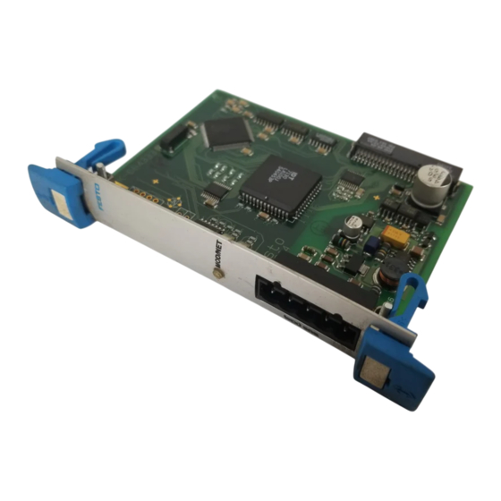
Publicité

Les langues disponibles
  • FR

Les langues disponibles

  • FRANÇAIS, page 39

Liens rapides

Smart Positioning Controller SPC200
Kurz−
beschreibung
Short
description
Feldbus−
Baugruppe Typ
SPC200−COM−DN2
Field bus module
type
SPC200−COM−DN2
Deutsch
English
Español
Français
Italiano
Svenska
688 396
0602a

Publicité

Table des Matières
loading

Sommaire des Matières pour Festo SPC200-COM-DN2

  • Page 1 Smart Positioning Controller SPC200 Kurz− beschreibung Short description Feldbus− Baugruppe Typ SPC200−COM−DN2 Field bus module type SPC200−COM−DN2 Deutsch English Español Français Italiano Svenska 688 396 0602a...
  • Page 2 ......... . . Edition: 0602a Original: de © (Festo SE & Co. KG, D 73726 Esslingen, Germany, 2006) Internet: http://www.festo.com E−Mail: service_international@festo.com...
  • Page 3 Aktoren können ungewollt aktiviert und der SPC200 beschädigt werden, wenn Baugruppen bei eingeschal teter Energieversorgung hinzugefügt oder entfernt werden. Schalten Sie vor Installations− und Wartungs arbeiten die Energiequellen in dieser Reihenfolge ab: 1. Druckluftversorgung 2. Last− und Betriebsspannungsversorgung. Festo SPC200−COM−DN2 0602a Deutsch...
  • Page 4 Alle E/As zusätzlich installierter E/A−Bau gruppen sind frei programmierbar. Baugruppen ausbauen 1. Erst Druckluft abschalten, danach Spannung! 2. Anschlusskabel auf der Baugruppenfront lösen und abziehen. 3. Beide Sicherungshebel durch Verschieben entriegeln (siehe folgendes Bild). Festo SPC200−COM−DN2 0602a Deutsch...
  • Page 5 4. Baugruppe an der Frontplatte fassen und herausziehen. 5. Frei bleibende Steckplätze mit Blindplatten verschließen. Richtung zum Entriegeln Frontplatte der Baugruppe Verriegelt selbsttätig Messerleiste Sicherungshebel Führungsschiene Festo SPC200−COM−DN2 0602a Deutsch...
  • Page 6 Bauteile auf der Leiterplatte beschädigt werden. 4. Achten Sie darauf, dass die Stecker der Messerleisten richtig aufeinander liegen. Schieben Sie die Bau gruppe dann mit leichtem Druck vollständig ein. Daraufhin verriegeln die Sicherungshebel selbsttätig (siehe Bild). Festo SPC200−COM−DN2 0602a Deutsch...
  • Page 7 Vermeiden Sie zu große Entfernungen zwischen dem Netzteil für die Busspannungsversorgung und dem Feldbusknoten des SPC200. Empfehlung: Platzieren Sie das Netzteil etwa in der Busmitte. Wählen Sie angemessene Leitungsquerschnitte und berücksichti gen Sie den Spannungsabfall auf der Versorgungsleitung. Festo SPC200−COM−DN2 0602a Deutsch...
  • Page 8 S Schließen Sie den Schirm an. Befindet sich der SPC200 am Ende des Feldbusses, ist zwischen die Adern Data + (Pin 4) und Data − (Pin 2) des Feldbussteckers ein Abschlusswiderstand (120 , 0,25 Watt) zu installieren. Festo SPC200−COM−DN2 0602a Deutsch...
  • Page 9 Start/Stopp oder Satzselektion 6. Feldbuskarte konfigurieren Protokollvariante auswählen (nur SPC200−COM−DN2) Busadresse festlegen Baudrate festlegen E/A−Bereiche konfigurieren (siehe nächste Seite) 7. Bei Bedarf E/A−Zuordnung (IO−Mapping) vornehmen. 8. Einstellungen mit OK bestätigen. 9. Projekt vollständig in den SPC200 laden. Festo SPC200−COM−DN2 0602a Deutsch...
  • Page 10 2 Byte Steuersignale Q10.15 DeviceNet− (immer) I10.0 ... 8 Byte Zur genauen Belegung Profile 13.15 siehe die Beschreibung P BE SPC200 COM CAN P.BE−SPC200−COM−CAN Q10.0 ... 8 Byte DN−... 13.15 E/A−Adressbereich der Feldbus−Baugruppe aus Sicht des SPC200 Festo SPC200−COM−DN2 0602a Deutsch...
  • Page 11 SPC200 hat Kommunika dung unterbrochen. tions−Time−Out erkannt. Master auf Kommunika− tionsfähigkeit prüfen. SPC200 wurde über einen S Time−Out Zustand des längeren Zeitraum SPC200 zurücksetzen (Time−Out−Zeit) nicht durch neues Allokieren. mehr angesprochen SPC200 an den Bus neu zuschalten. Festo SPC200−COM−DN2 0602a Deutsch...
  • Page 12 S Baudrate prüfen/ wurde doppelt vergeben korrigieren S Feldbusadresse korrigieren 5.2 Weitere Diagnosemöglichkeiten Im Kapitel 6 der Beschreibung P.BE−SPC200−COM−CANDN−... finden Sie zusätzlich Informationen über: Diagnose mit WinPISA Auslesen der 8−stelligen Diagnoseinformationen des SPC200 über Feldbus Fehlercode von DeviceNet−Profile Festo SPC200−COM−DN2 0602a Deutsch...
  • Page 13: Technische Daten

    über Feldbuskabel SPC200−COM−CAN: 11,5 ..26,5 V) Stromaufnahme über 50 mA (typisch) Feldbuskabel Kabeltyp Siehe Handbuch Ihrer Steuerung. Spannungsversorgung interne Über SPC200 Elektronik Typische Stromaufnahme 50 mA Elektromagnetische Siehe Konformitätserklärung. Verträglichkeit Schwingung und Schock Siehe System−Handbuch zum SPC200 Festo SPC200−COM−DN2 0602a Deutsch...
  • Page 14 Festo SPC200−COM−DN2 0602a Deutsch...
  • Page 15 Before carrying out installation and/or maintenance work, switch off the following sources of energy in the sequence specified: 1. the compressed air supply 2. the load and operating voltage supply. Festo SPC200−COM−DN2 0602a English...
  • Page 16 Removing modules 1. Switch off first the compressed air, then the voltage! 2. Disconnect and remove the connecting cable from the front of the module. 3. Unlock both locking levers by pushing them back (see following diagram). Festo SPC200−COM−DN2 0602a English...
  • Page 17 4. Grip the module by the front plate and pull it out. 5. Seal the unused slots with blanking plugs. Direction for unlocking Front plate of the module Locks automatically Terminal strip Locking lever Guide rail Festo SPC200−COM−DN2 0602a English...
  • Page 18 4. Make sure that the plugs on the terminal strips are correctly aligned. Then gently push the module in completely. The locking levers will then lock automatically (see diagram). Festo SPC200−COM−DN2 0602a English...
  • Page 19 SPC200. Recommendation: Place the power unit approximately in the centre of the bus. Select suitable cable cross−sectional areas and take into account the voltage drop on the supply cable. Festo SPC200−COM−DN2 0602a English...
  • Page 20 If the SPC200 is at the end of the field bus, a terminating resistor (120 , 0.25 Watt) must be fitted between the pins Data + (pin 4) and Data − (pin 2) of the field bus plug. Festo SPC200−COM−DN2 0602a English...
  • Page 21 Select protocol variant (only SPC200−COM−DN2) Define bus address Define baud rate Configure I/O ranges (see next page) 7. If necessary, undertake I/O assignment (IO mapping). 8. Confirm settings with OK. 9. Load the project completely into the SPC200. Festo SPC200−COM−DN2 0602a English...
  • Page 22 I10.0 ... 8 bytes For the exact profiles 13.15 assignment see the manual P BE SPC200 manual P.BE−SPC200− Q10.0 ... 8 bytes COM−CANDN−... 13.15 I/O address range of the field bus module as viewed by the SPC200 Festo SPC200−COM−DN2 0602a English...
  • Page 23 Check master for ability Time−Out. to communicate. The SPC200 has not been S Reset the Time−Out addressed for a long time status of the SPC200 by (Time−Out time). new allocation. Connect the SPC200 to the bus again. Festo SPC200−COM−DN2 0602a English...
  • Page 24 5.2 Further diagnostic possibilities In chapter 6 of the manual P.BE−SPC200−COM−CANDN−... you will also find information on: Diagnosis with WinPISA Reading the 8−figure diagnostic information of the SPC200 via the field bus Fault code of the DeviceNet profile Festo SPC200−COM−DN2 0602a English...
  • Page 25: Technical Specifications

    Cable type See controller manual Power supply for the internal Via SPC200 electronics Typical current consumption 50 mA Electromagnetic compatibility See declaration of conformity Vibration and shock See system manual for the SPC200 Festo SPC200−COM−DN2 0602a English...
  • Page 26 Festo SPC200−COM−DN2 0602a English...
  • Page 27: Instrucciones Para El

    1. la alimentación de aire comprimido 2. las alimentaciones de la tensión de carga y de funcionamiento. Festo SPC200−COM−DN2 0602a Español...
  • Page 28 1. Desconecte el aire comprimido y a continuación la tensión. 2. Desconecte y retire el cable de conexión de la parte frontal del módulo. 3. Desbloquee ambas palancas de bloqueo presionándo las hacia atrás (véase la figura). Festo SPC200−COM−DN2 0602a Español...
  • Page 29 4. Sujete el módulo por la placa frontal y tire de él. 5. Tape las ranuras sin utilizar con tapas ciegas. Sentido de desbloqueo Placa frontal del módulo Se bloquea automática Regleta de terminales mente Raíl de guía Palanca de bloqueo Festo SPC200−COM−DN2 0602a Español...
  • Page 30 4. Asegúrese de que las clavijas de la regleta terminal estén correctamente alineadas. Presione completa mente el módulo con cuidado. Las palancas de retención se bloquearán automática mente (ver figura). Festo SPC200−COM−DN2 0602a Español...
  • Page 31 SPC200. Recomendación: Disponga la fuente de alimentación aproximadamente en el centro del bus. Elija cables de sección adecuada y tenga en cuenta la caída de tensión en el cable de alimentación. Festo SPC200−COM−DN2 0602a Español...
  • Page 32 Si el SPC200 se halla al final del bus de campo, deberá montar una resistencia terminadora (120 , 0,25 Watt) entre los pines Data + (pin 4) y Data − (pin 2) de la clavija del bus de campo. Festo SPC200−COM−DN2 0602a Español...
  • Page 33 Definir la velocidad de transmisión Configurar los márgenes de I/O (ver página siguiente) 7. Si es necesario, realizar la asignación de I/O (mapeado de I/O). 8. Confirmar los ajustes con OK. 9. Cargar el proyecto completamente en el SPC200. Festo SPC200−COM−DN2 0602a Español...
  • Page 34 (siempre) I10.0... 8 bytes Para la asignación profile 13.15 exacta véase el manual P BE SPC200 manual P.BE−SPC200− Q10.0... 8 bytes COM−CANDN−... 13.15 Margen de direcciones I/O del módulo de bus de campo en relación al SPC200 Festo SPC200−COM−DN2 0602a Español...
  • Page 35 Verificar la comunicación nicación. con el master. El SPC200 no ha sido S Restablecer el estado direccionado durante un Time−Out del SPC200 con largo tiempo una nueva asignación. (Tiempo de Time−Out). Conectar el SPC200 de nuevo al bus. Festo SPC200−COM−DN2 0602a Español...
  • Page 36 En el capítulo 6 del manual P.BE−SPC200−COM−CANDN−... también hallará información sobre: Diagnosis con WinPISA Lectura de la información de diagnosis de 8 cifras del SPC200 a través del bus de campo. Código de fallo del DeviceNet profile" Festo SPC200−COM−DN2 0602a Español...
  • Page 37: Especificaciones Técnicas

    Tipo de cable Véase el manual del controlado Alimentación para la Vía SPC200 electrónica interna Consumo de corriente típico 50 mA Compatibilidad Ver declaración de conformidad electromagnética Vibración y choque Ver manual del sistema para el SPC200 Festo SPC200−COM−DN2 0602a Español...
  • Page 38 Festo SPC200−COM−DN2 0602a Español...
  • Page 39 SPC200 endommagé. Avant tous travaux d’installation et d’entretien, couper les sources d’énergie suivantes dans l’ordre indiqué : 1. l’alimentation en air comprimé, 2. les alimentat. en tension de puissance et de service. Festo SPC200−COM−DN2 0602a Français...
  • Page 40: Démontage Et Montage Des Cartes

    Démontage des cartes 1. Couper d’abord l’air comprimé, puis la tension ! 2. Débrancher le câble de connexion à l’avant de la carte. 3. Déverrouiller les deux leviers de blocage en les poussant (voir figure suivante). Festo SPC200−COM−DN2 0602a Français...
  • Page 41 4. Saisir la carte par la face avant et la retirer. 5. Protéger les emplacements libres à l’aide de plaques d’obturation. Sens de déverrouillage Face avant de la carte Verrouillage automatique Contacts Levier de blocage Rail de guidage Festo SPC200−COM−DN2 0602a Français...
  • Page 42 4. Veiller à ce que les contacts des connecteurs soient bien positionnés l’un sur l’autre. Enfoncer complète ment la carte en appliquant une légère pression. Ensuite, les leviers de blocage se verrouillent automa tiquement (voir figure). Festo SPC200−COM−DN2 0602a Français...
  • Page 43 SPC200. Recommandation : Placer le bloc d’alimentation au centre du bus. Sélection ner les sections de câble appropriées et tenir compte de la chute de tension sur le câble d’alimentation. Festo SPC200−COM−DN2 0602a Français...
  • Page 44 Si le SPC200 se trouve à l’extrémité du bus de terrain, installer une résistance de terminaison (120 , 0,25 watts) entre les fils Données + (broche 4) et Données − (broche 2) du connecteur de bus de terrain. Festo SPC200−COM−DN2 0602a Français...
  • Page 45: Instructions De Mise En Service

    Déterminer la vitesse de transmission Configurer les espaces d’E/S (v. page suivante) 7. Si nécessaire, exécuter l’attribution d’E/S (mapping ES). 8. Valider le réglage en cliquant sur OK. 9. Charger complètement le projet dans le SPC200. Festo SPC200−COM−DN2 0602a Français...
  • Page 46 Pour une affectation −profile 13.15 précise, voir la description P BE description P.BE− Q10.0 ... 8 octets SPC200−COM− 13.15 CANDN−... Espace d’adresses d’E/S de la carte de bus de terrain du point de vue du SPC200 Festo SPC200−COM−DN2 0602a Français...
  • Page 47 Le SPC200 n’a plus été de communication du appelé pendant un laps de dispositif maître. temps trop long S Réinitialiser le Time−Out (Time−Out). du SPC200 en effectuant une nouvelle affectation. Brancher à nouveau le SPC200 sur le bus. Festo SPC200−COM−DN2 0602a Français...
  • Page 48: Autres Possibilités De Diagnostic

    Des informations supplémentaires sur les points suivants sont fournies au chapitre 6 du manuel P.BE−SPC200−COM− CANDN−... : Diagnostic à l’aide de WinPISA Lecture des informations de diagnostic à 8 chiffres du SPC200 sur le bus de terrain Codes d’erreur du DeviceNet−profile" Festo SPC200−COM−DN2 0602a Français...
  • Page 49: Caractéristiques Techniques

    Consulter le manuel de l’automate Alimentation de l’électroni Via SPC200 que interne Intensité absorbée type 50 mA Compatibilité Voir la déclaration de conformité électromagnétique Tenue aux vibrations et aux Voir le manuel système du SPC200 chocs Festo SPC200−COM−DN2 0602a Français...
  • Page 50 Festo SPC200−COM−DN2 0602a Français...
  • Page 51 Prima di eseguire i lavori di installazione e manutenzione, disattivare le fonti d’energia nella seguente successione: 1. alimentazione dell’aria 2. alimentazione della tensione di carico e di esercizio. Festo SPC200−COM−DN2 0602a Italiano...
  • Page 52 Smontaggio dei moduli 1. Disinserire prima l’aria compressa, poi la tensione! 2. Sbloccare e sfilare il cavo di collegamento dalla parte anteriore del modulo. 3. Spostare entrambe le levette di bloccaggio per sbloccarle (vedi figura seguente). Festo SPC200−COM−DN2 0602a Italiano...
  • Page 53 4. Prendere il modulo dal pannello frontale e sfilarlo all’esterno. 5. Chiudere gli slot non occupati con le apposite piastre cieche. Direzione di sbloccaggio Piastra frontale del modulo Bloccaggio automatico Morsettiera maschio Levetta di bloccaggio Guida Festo SPC200−COM−DN2 0602a Italiano...
  • Page 54 4. Assicurarsi che i connettori delle morsettiere maschio siano sovrapposti correttamente. Poi inserire il modulo completamente esercitando una leggera pressione. Le levette di bloccaggio scattano automaticamente bloccandolo in posizione (vedi figura). Festo SPC200−COM−DN2 0602a Italiano...
  • Page 55 Non collocare il nodo fieldbus dell’SPC200 a una distanza eccessiva dall’alimentatore per l’alimentazione bus. Suggerimento: Collocare l’alimentatore circa a metà della linea bus. Selezionare sezioni di linea adatte e tenere conto del calo di tensione sulla linea di alimentazione. Festo SPC200−COM−DN2 0602a Italiano...
  • Page 56 S Collegare lo schermo. Se l’SPC200 è posizionato all’estremità finale di una linea fieldbus, è necessario installare tra i conduttori Data + (pin 4) e Data − (pin 2) del connettore bus una resistenza terminale (120 , 0,25 Watt). Festo SPC200−COM−DN2 0602a Italiano...
  • Page 57: Indicazioni Per La Messa In Servizio

    Selezionare variante di protocollo (solo SPC200−COM−DN2) Definire l’indirizzo bus Definire il baudrate Configurare i gruppi I/O (vedi pagina successiva) 7. Eseguire se necessario l’assegnazione I/O (IO−Mapping). 8. Confermare le impostazioni con OK. 9. Ricaricare completamente il progetto nell’SPC200. Festo SPC200−COM−DN2 0602a Italiano...
  • Page 58 Segnali di comando Q10.15 DeviceNet− (sempre) I10.0 ... 8 byte Per l’occupazione Profile 13.15 precisa fare riferimento alla riferimento alla descrizione P.BE− Q10.0 ... 8 byte SPC200−COM−CANDN 13.15 −... Range indirizzi I/O del modulo fieldbus secondo l’SPC200 Festo SPC200−COM−DN2 0602a Italiano...
  • Page 59 Controllare che il Master zione sia predisposto per la L’SPC200 non è stato comunicazione. azionato per un tempo S Resettare il Time−Out prolungato (Time−Out) dell’SPC200 mediante riallocazione. Ricollegare l’SPC200 al bus. Festo SPC200−COM−DN2 0602a Italiano...
  • Page 60 5.2 Ulteriori possibilità diagnostiche Nel cap. 6 della descrizione P.BE−SPC200−COM−CANDN−... è possibile reperire informazioni anche riguardanti: la diagnosi con WinPISA la lettura delle informazioni diagnostiche a 8 cifre dell’SPC200 tramite fieldbus il codice di errore di DeviceNet profile" Festo SPC200−COM−DN2 0602a Italiano...
  • Page 61: Dati Tecnici

    Tipo di cavo Vedi manuale del sistema di comand. Alimentazione di tensione Tramite SPC200 dell’elettronica interna Assorbimento di corrente 50 mA tipico Compatibilità Vedi dichiarazione di conformità. elettromagnetica Vibrazioni e urti Cfr. il manuale di sistema dell’SPC200 Festo SPC200−COM−DN2 0602a Italiano...
  • Page 62 Festo SPC200−COM−DN2 0602a Italiano...
  • Page 63 Varning Arbetselement kan aktiveras oavsiktligt och SPC200 kan skadas om komponenter ansluts eller tas bort vid tillkopplad energitillförsel. Innan installations− och underhållsarbeten påbörjas ska energikällorna kopplas från i följande ordning: 1. tryckluftsmatning 2. matningsspänning. Festo SPC200−COM−DN2 0602a Svenska...
  • Page 64 Endast en fältbusskomponent får installeras. Alla I/O:s på installerade I/O−komponenter kan programmeras fritt. Demontera komponenter 1. Koppla först ifrån tryckluften, sedan spänningen! 2. Lossa och avlägsna anslutningskabeln på komponentens framsida. 3. Frigör båda säkerhetsspakarna genom att skjuta på dem (se följande bild). Festo SPC200−COM−DN2 0602a Svenska...
  • Page 65 4. Fatta komponenten vid frontplattan och dra ut den. 5. Täck lediga kontaktplatser med blindplattor. Öppningsriktning Komponentens frontplatta Låses automatiskt Multipol Låsspak Styrskena Festo SPC200−COM−DN2 0602a Svenska...
  • Page 66 4. Se till att multipolernas hankontakter ligger rätt på varandra. Skjut sedan in komponenten ända in med ett lätt tryck. Därpå låser sig säkerhetsspakarna automatiskt (se bild). Festo SPC200−COM−DN2 0602a Svenska...
  • Page 67 11 ... 30 V SPC200−COM−CAN 24 V 11,5 ... 26,5 V Undvik för stora avstånd mellan busspännings− försörjningens nätdel och SPC200−fältbussnoden. Rekommendation: Placera nätaggregatet ungefär mitt på bussen. Välj passande tvärsnitt för ledningar och beakta spänningsfallet på försörjningsledningen. Festo SPC200−COM−DN2 0602a Svenska...
  • Page 68 S Beakta polariteten vid anslutning av dataledningar och spänningsmatningsledningar. S Anslut skärmen. Om SPC200 befinner sig vid fältbussens ände ska ett termineringsmotstånd (120 , 0,25 watt) installeras mellan fältbusskontaktens ledare data + (stift 4) och data − (stift 2). Festo SPC200−COM−DN2 0602a Svenska...
  • Page 69 Start/stopp eller Satsselektion 6. Konfigurera fältbusskort Välj protokollvariant (bara SPC200−COM−DN2) Ange bussadress Ange överföringshastighet Konfigurera I/O−områden (se nästa sida) 7. Utför vid behov I/O−tilldelning (IO−mapping). 8. Bekräfta inställningarna med OK. 9. Ladda projekt fullständigt i SPC200. Festo SPC200−COM−DN2 0602a Svenska...
  • Page 70 Q10.0 ... 2 byte Styrsignaler Q10.15 DeviceNet− (alltid) I10.0 ... 8 byte För exakt beläggning, Profile 13.15 se manualen P.BE− SPC200 COM CANDN SPC200−COM−CANDN Q10.0 ... 8 byte −... 13.15 I/O−adressområde för fältbusskomponenter utgående från SPC200 Festo SPC200−COM−DN2 0602a Svenska...
  • Page 71 S Fysisk bussförbindelse rött SPC200 har registrerat bruten. Kontrollera kommunikations−timeout. master beträffande kommunikationsförmåga. SPC200 har under en S Återställ Time−Out av längre tid (Time−Out−tid) SPC200 genom ny inte tagit emot någon allokering. Starta om signal SPC200 på bussen. Festo SPC200−COM−DN2 0602a Svenska...
  • Page 72 överföringshastighet fältbussadress har S Korrigera fältbussadress tilldelats dubbelt. 5.2 Ytterligare diagnosmöjligheter I kap. 6 i manualen P.BE−SPC200−COM−CANDN−... finns ytterligare information om: Diagnos med WinPISA Avläsning av den 8−siffriga diagnosinformationen för SPC200 via fältbussen Felkod för DeviceNet−profile" Festo SPC200−COM−DN2 0602a Svenska...
  • Page 73: Tekniska Data

    SPC200−COM−CAN: 11,5...26,5 V) Strömförbrukning via 50 mA (typisk) fältbusskabel Kabeltyp Se manualen till ditt styrsystem Spänningsmatning intern Via SPC200 elektronik Typisk strömförbrukning 50 mA Elektromagnetisk Se försäkran om överensstämmelse kompatibilitet Vibrationer och stötar Se systemmanual till SPC200 Festo SPC200−COM−DN2 0602a Svenska...
  • Page 74 Festo SPC200−COM−DN2 0602a Svenska...

Ce manuel est également adapté pour:

Spc200-com-can

Table des Matières