Télécharger Imprimer la page
Festo SPC200 Mode D'emploi
Masquer les pouces Voir aussi pour SPC200:

Publicité

Les langues disponibles
  • FR

Les langues disponibles

  • FRANÇAIS, page 33

Liens rapides

Smart Positioning Controller SPC200
Kurz-
beschreibung
Short
description
Feldbus-
Baugruppe
Typ
SPC200-COM-CAN
Field bus module
type
SPC200-COM-CAN
– Deutsch
– English
– Español
– Français
– Italiano
– Svenska
396 537
0012NH

Publicité

loading

Sommaire des Matières pour Festo SPC200

  • Page 1 Smart Positioning Controller SPC200 Kurz- beschreibung Short description Feldbus- Baugruppe SPC200-COM-CAN Field bus module type SPC200-COM-CAN – Deutsch – English – Español – Français – Italiano – Svenska 396 537 0012NH...
  • Page 2 ......... . . Edition: 0012NH Original: de © (Festo AG & Co., D-73726 Esslingen, Germany, 2000) Internet: http://www.festo.com E-Mail: service_international@festo.com...
  • Page 3 BenutzerhinweiseDeutsch Die Feldbus-Baugruppe Typ SPC200-COM-CAN dient be- stimmungsgemäß zur Ankopplung des SPC200 an Device- Net. Mit dieser Feldbus-Baugruppe kann der SPC200 als Slave am entsprechenden Feldbus betrieben werden. Zur komfortablen Inbetriebnahme eines SPC200 mit integrier- ter Feldbus-Baugruppe ist das Software-Paket WinPISA ab Version 4.1 erforderlich.
  • Page 4 Es darf nur eine Feldbus-Baugruppe instal- liert werden. Alle E/As installierter E/A-Baugruppen sind frei programmierbar. Baugruppen ausbauen 1. Druckluftversorgung und Betriebsspannung abschal- ten. 2. Anschlusskabel auf der Baugruppenfront lösen und abziehen. 3. Beide Sicherungshebel durch Verschieben entriegeln (siehe folgendes Bild). Festo SPC200-COM-CAN 0012NH Deutsch...
  • Page 5 4. Baugruppe an der Frontplatte fassen und hinaus- ziehen. 5. Ggf. freibleibende Steckplätze mit Blindplatten verschließen. Richtung zum Entriegeln Frontplatte der Baugruppe Verriegelt selbsttätig Messerleiste Sicherungshebel Führungsschiene Festo SPC200-COM-CAN 0012NH Deutsch...
  • Page 6 Bauteile auf der Leiterplatte beschädigt werden. 4. Achten Sie darauf, dass die Stecker der Messerleisten richtig aufeinander liegen. Schieben Sie die Bau- gruppe dann mit leichtem Druck vollständig ein. Daraufhin verriegeln die Sicherungshebel selbsttätig (siehe Bild). Festo SPC200-COM-CAN 0012NH Deutsch...
  • Page 7 Verwenden Sie als Feldbusleitung eine verdrillte, ge- schirmte 4-Drahtleitung. Über die Feldbusleitung wird die Busschnittstelle und die interne Logik der Feldbus-Bau- gruppe versorgt. Pin-Belegung Beschreibung 0 V-Busschnittstelle/Logik (CAN_GND) Data - (CAN_L) Schirm (CAN_SHLD) Data + (CAN_H) DC + 24 V-Busschnittstelle/Logik (CAN_V+) Festo SPC200-COM-CAN 0012NH Deutsch...
  • Page 8 Feldbusschnittstelle und der Spannungsversor- gung der Busschnittstelle/internen Logik. S Schließen Sie den Schirm an. Befindet sich der SPC200 am Ende des Feldbusses, ist zwischen die Adern Data + (Pin 4) und Data - (Pin 2) des Feldbussteckers ein Abschlusswiderstand (120 Ohm, 0,25 Watt) zu installieren.
  • Page 9 Inbetriebnahmehinweise Die Feldbus-Adresse des SPC200 können Sie mit dem Soft- ware-Paket WinPISA (ab Version 4.1) oder dem Bedienfeld einstellen. Der SPC200 kommuniziert mit dem Master über ein E/A- Feld (interne Ein-/Ausgänge). Die zulässige Anzahl der konfigurierbaren Ein- und Ausgänge ist von der genutzten Betriebsart des SPC200 abhängig (max.
  • Page 10 Diagnose 5.1 Anzeige der Mod-/Net-LED Die Bi-Color-LED auf der Feldbus-Baugruppe ermöglicht eine Schnell-Diagnose über den Kommunikationszustand vor Ort. Die Fehlermeldungen des SPC200 lassen sich über die Bit Strobed I/O Message Connection übertragen (siehe Beschreibung). Betriebszustand Fehlerbehandlung leuchtet Normal; der SPC200 ist keine grün...
  • Page 11 Betriebszustand Fehlerbehandlung S schlechte physikalische leuchtet schwerer Kommunikations- fehler Busverbindung; Verbin- – SPC200 hat zu viele feh- dung prüfen. S stark gestörter Bus; lerhafte Telegramme auf dem Bus entdeckt und Störungen eliminieren, nimmt an der Buskommu- Schirmung prüfen. S Spannungsversorgung nikation nicht mehr teil.
  • Page 12: Technische Daten

    Schwingung und Schock – Schwingung geprüft nach DIN/IEC 68 Teil 2–6 Schärfegrad 1 – Schock geprüft nach DIN/IEC 68 Teil 2–27 Schärfegrad 2 1) Mit einer Einzelgenehmigung auch einsetzbar im Wohnbereich (Wohn-, Geschäfts- und Gewerbebereich, Kleinbetriebe). Festo SPC200-COM-CAN 0012NH Deutsch...
  • Page 13 The field bus module type SPC200-COM-CAN has been designed for coupling the SPC200 to the DeviceNet. With this field bus module the SPC200 can be operated as a slave on the relevant field bus. For user-friendly commis- sioning of an SPC200 with the integrated field bus module, you will require the WinPISA software package as from version 4.1.
  • Page 14 Removing the modules 1. Switch off the compressed air supply and operating voltage. 2. Disconnect and remove the connecting cable on the front of the module. 3. Unlock both locking levers by pushing them (see fol- lowing diagram). Festo SPC200-COM-CAN 0012NH English...
  • Page 15 4. Hold the module on the front plate and pull it out. 5. If applicable, seal unused locations with blank plates. Direction for unlocking Front plate of module Locks automatically Multi connector strip Locking lever Guide rail Festo SPC200-COM-CAN 0012NH English...
  • Page 16 4. Make sure that the plugs of the multi connector strip are inserted correctly. Then gently press in the module completely. The locking levers will then lock automati- cally (see diagram). Festo SPC200-COM-CAN 0012NH English...
  • Page 17 Pin assignment User manual 0 V bus interface/logic (CAN_GND) Data - (CAN_L) Screening/shield (CAN_SHLD) Data + (CAN_H) +24 V DC bus interface/logic (CAN_V+) Festo SPC200-COM-CAN 0012NH English...
  • Page 18 S Connect the screening. If the SPC200 is at the end of the field bus, a terminating resistor (120 Ohm, 0.25 Watt) must be fitted between the cores Data + (pin 4) and Data - (pin 2) of the field bus plug.
  • Page 19 Instructions on commissioning You can set the field bus address of the SPC200 with the WinPISA software package (as from version 4.1) or with the control panel. The SPC200 communicates with the master via an I/O field (internal inputs/outputs). The permitted number of confi- gurable inputs and outputs depends on the operating mode of the SPC200 used (max.
  • Page 20 5.1 Display on the Mod/Net LED The two-coloured LED on the field bus module enables speedy on-the-spot diagnosis of the state of communica- tion. The error messages of the SPC200 can be transmitted via the bit Strobed I/O Message Connection (see manual). Operating status...
  • Page 21 Flashes Fault can be eliminated – SPC200 has recognized interrupted. Check communication-time-out master for communica- – SPC200 has not been ad- tion ability S Reset time-out status of dressed for a long period (time-out time) SPC200 and allocate new status. Switch SPC200...
  • Page 22: Technical Specifications

    Tested as per DIN/IEC 68 part 2-6 Severity 1 – Shock Tested as per DIN/IEC 68 part 2-27 severity class 2 1) With individual authorization can be used in residential areas (living, business and commercial areas, small firms). Festo SPC200-COM-CAN 0012NH English...
  • Page 23 SPC200 puede funcionar como un slave en el correspondiente bus de campo. Para una cómoda puesta a punto de un SPC200 con el módulo de bus de campo integrado, necesitará el paquete de soft- ware WinPisa a partir de la versión 4.1.
  • Page 24 1. Desconectar el aire comprimido y la tensión de alimen- tación. 2. Desconectar y retirar el cable de conexión en la parte frontal del módulo. 3. Desbloquear ambas palancas de bloqueo empujándo- las (véase la figura siguiente). Festo SPC200-COM-CAN 0012NH Español...
  • Page 25 4. Sostener el módulo por la placa frontal y tirar de él. 5. Si es aplicable, tapar las posiciones no utilizadas con placas ciegas. Sentido para el desbloqueo Placa frontal del módulo Se bloquea automática- Multiconector mente Raíl de guía Palanca de bloqueo Festo SPC200-COM-CAN 0012NH Español...
  • Page 26 4. Asegurarse de que las clavijas del multiconector se insertan correctamente. A continuación introducir el módulo completamente. Las palancas de bloqueo se cerrarán automáticamente (véase figura). Festo SPC200-COM-CAN 0012NH Español...
  • Page 27 Asignación de pines Conexión asignada 0 V interface del bus/lógica (CAN_GND) Data - (CAN_L) Apantallamiento (CAN_SHLD) Data + (CAN_H) +24 V DC interface del bus/lógica (CAN_V+) Festo SPC200-COM-CAN 0012NH Español...
  • Page 28 S Conectar el apantallamiento. Si el SPC200 se halla al final del bus de campo, debe mon- tarse una resistencia de terminación (120 Ohm, 0,25 Watt) entre los hilos Data + (pin 4) y Data - (pin 2) en la clavija del bus de campo.
  • Page 29 WinPisa (a partir de la versión 4.1) o con el panel de control. El SPC200 comunica con el master a través de un campo de I/O (entradas/salidas internas). El número permitido de entradas y salidas configurable depende del modo de fun- cionamiento del SPC200 utilizado (máx.
  • Page 30 El LED bicolor en el módulo del bus de campo permite un rápido diagnóstico en el propio lugar, del estado de la comunicación. Los mensajes de error del SPC200 pueden transmitirse a través del bit Strobed I/O Message Connec- tion (véase el manual).
  • Page 31 S Restablecer el estado de – El SPC200 no ha sido di- reccionado durante un time-out del SPC200 y largo período (tiempo asignar nuevo estado. desbordado/time-out)
  • Page 32: Especificaciones Técnicas

    Verificada según DIN/IEC 68 parte 2-6 severidad 1 – Choque Verificada según DIN/IEC 68 parte 2-27 severidad clase 2 1) Con autorización individual puede utilizarse en zonas residenciales (viviendas, zonas comerciales y de negocio, pequeñas empresas). Festo SPC200-COM-CAN 0012NH Español...
  • Page 33 La carte de bus de terrain type SPC200-COM-CAN sert conformément à l’usage prévu au raccordement du SPC200 sur DeviceNet. Cette carte de bus de terrain per- met de faire fonctionner le SPC200 comme esclave sur le bus de terrain correspondant. Pour la mise en service confortable d’un SPC200 avec carte de bus de terrain inté-...
  • Page 34: Démontage Et Montage Des Cartes

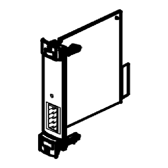
    Démontage des cartes 1. Couper l’alimentation en air comprimé et l’alimenta- tion électrique. 2. Débrancher le câble de connexion à l’avant de la carte. 3. Déverrouiller les deux leviers de blocage en les pous- sant (voir figure suivante). Festo SPC200-COM-CAN 0012NH Français...
  • Page 35 4. Saisir la carte par la face avant et la retirer. 5. Le cas échéant, fermer les emplacements libres à l’aide de plaques d’obturation. Sens de déverrouillage Face avant de la carte Verrouillage automatique Connecteur Levier de blocage Rail de guidage Festo SPC200-COM-CAN 0012NH Français...
  • Page 36 4. Veiller à ce que les contacts des connecteurs soient bien positionnés l’un sur l’autre. Enfoncer complète- ment la carte en appliquant une légère pression. En- suite, les leviers de blocage se verrouillent automati- quement (voir figure). Festo SPC200-COM-CAN 0012NH Français...
  • Page 37 Affectation des broches Broche Description Interface de bus/logique 0 V (CAN_GND) Données - (CAN_L) Blindage (CAN_SHLD) Données + (CAN_H) Interface de bus/logique + 24 V CC (CAN_V+) Festo SPC200-COM-CAN 0012NH Français...
  • Page 38 S Raccorder le blindage. Si le SPC200 se trouve à l’extrémité du bus de terrain, instal- ler une résistance de terminaison (120 Ohm, 0,25 Watt) entre les fils Données + (broche 4) et Données – (broche 2) du connecteur de bus de terrain.
  • Page 39: Instructions De Mise En Service

    Instructions de mise en service L’adresse de bus de terrain du SPC200 peut être réglée à l’aide du progiciel WinPISA (à partir de la version 4.1) ou du pupitre de commande. Le SPC200 communique avec le Maître par un champ d’E/S (entrées/sorties internes).
  • Page 40 5.1 Affichage des LED Mod/Net La LED bicolore sur la carte de bus de terrain permet un diagnostic rapide de l’état de communication sur place. Les messages d’erreur du SPC200 sont transmis via le Bit Strobed I/O Message Connection (voir manuel d’utilisa- tion).
  • Page 41 S Mauvaise liaison physi- Erreur de communication rouge grave que avec le bus ; vérifier s’allume – Le SPC200 a détecté trop la liaison. S Perturbation importante de télégrammes erronés sur le bus et a interrompu du bus ; éliminer les inci- la communication avec le dents, vérifier le blindage.
  • Page 42: Caractéristiques Techniques

    2-6 Niveau de sévérité 1 – Chocs Contrôlée selon DIN / CEI 68 partie 2-27 Niveau de sévérité 2 1) Peut également être utilisé sous autorisation particulière dans des locaux d’habitation (logements, commerces ou petites entreprises). Festo SPC200-COM-CAN 0012NH Français...
  • Page 43 Avvertenza Aggiungendo o togliendo i moduli con l’alimentazione di tensione inserita, si possono attivare inavvertita- mente gli attuatori e danneggiare l’SPC200. Prima di effettuare lavori di installazione e manutenzione, scol- legare le seguenti fonti di energia nell’ordine indicato: 1. aria compressa 2.
  • Page 44 1. Scollegare l’alimentazione di aria compressa e della tensione di esercizio. 2. Allentare e disinserire il cavo di collegamento dalla parte anteriore del modulo. 3. Spostare e sbloccare le due levette di bloccaggio (vedi figura successiva). Festo SPC200-COM-CAN 0012NH Italiano...
  • Page 45 4. Prendere il modulo dalla parte frontale ed estrarlo. 5. Chiudere gli slot eventualmente liberi con le apposite piastre cieche. Sbloccaggio del modulo Piastra frontale del modulo Bloccaggio automatico Lamina Levetta di bloccaggio Profilo guida Festo SPC200-COM-CAN 0012NH Italiano...
  • Page 46 4. Accertarsi che i connettori maschio delle lamine siano sovrapposti correttamente. Inserire il modulo fino in fondo esercitando una leggera pressione. Le levette di bloccaggio scattano automaticamente bloccandolo in posizione (vedi figura). Festo SPC200-COM-CAN 0012NH Italiano...
  • Page 47 Il cavo Fieldbus assicura l’alimentazione elet- trica all’interfaccia bus e alla logica interna del modulo Fieldbus. Occupazione dei pin Descrizione 0 V- interfaccia bus/gruppo logico (CAN_GND) Data - (CAN_L) Schermo (CAN_SHLD) Data + (CAN_H) + 24 VCC -interfaccia bus/gruppo logico (CAN_V+) Festo SPC200-COM-CAN 0012NH Italiano...
  • Page 48 S Collegare lo schermo. Se l’SPC200 è posizionato all’estremità finale di una linea Fieldbus, installare una resistenza terminale (120 Ohm, 0,25 Watt) tra i conduttori Data + (Pin 4) e Data - (Pin 2). In caso di impiego di adattatori a T si consiglia di installare la resistenza terminale sull’uscita libera dell’adattatore.
  • Page 49 E’ possibile impostare l’indirizzo Fieldbus dell’SPC200 con il pacchetto software WinPISA (versione 4.1 o superiori) oppure con il quadro operativo. L’SPC200 comunica con il Master mediante un campo I/O (ingressi/uscite interni) Il numero consentito di ingressi e uscite configurabili dipende dal modo di funzionamento prescelto dell’SPC200 (max.
  • Page 50 Diagnosi 5.1 Visualizzazione del LED Mod/Net Il LED bicolore sul modulo Fieldbus consente una rapida diagnosi sullo stato della comunicazione nella periferica. E’ possibile trasmettere i messaggi di errore dell’SPC200 mediante Bit Strobed I/O Message Connection (vedi descrizione). Condizioni di Correzione dell’errore...
  • Page 51 Con- rosso time-out nella comunica- trollare che il Master sia zione. predisposto per la comu- – L’SPC200 non è stato uti- nicazione. S Resettare il time-out lizzato per lungo tempo (periodo di Time-Out) dell’SPC200 mediante riallocazione. Ricollegare l’SPC200 al bus.
  • Page 52: Dati Tecnici

    Parte 2-6 classe di precisione 1 – Urti Misurata a norma DIN/IEC 68 Parte 2-27 classe di precisione 2 1) È possibile utilizzare l’SPC200 anche in ambienti non industriali previa autorizzazione (abitazioni, locali commerciali, uffici, piccole aziende). Festo SPC200-COM-CAN 0012NH Italiano...
  • Page 53 AnvändaranvisningarSvenska Fältbusskomponent SPC200-COM-CAN har till uppgift att koppla SPC200 till DeviceNet. Med denna fältbusskompo- nent kan SPC200 vara i slavdrift på resp. fältbuss. För kom- fortabel idrifttagning av en SPC200 med integrerad fält- busskomponent krävs mjukvarupaketet WinPISA fr.o.m. version 4.1. Utförlig information om fältbusskomponenten finner du i manualen P.BE-SPC200-COM-CAN...-...
  • Page 54 Alla I/O:s på installerade I/O-kompo- nenter kan programmeras fritt. Demontera komponenter 1. Frånkoppla tryckluftsförsörjning och spänningsmat- ning. 2. Lossa och avlägsna anslutningskablar på komponen- tens framsida. 3. Öppna båda säkerhetsspakar genom att skjuta på dem (se följande bild). Festo SPC200-COM-CAN 0012NH Svenska...
  • Page 55 4. Fatta komponenten på frontplattan och dra ut den. 5. Tillslut om så erfordras tomma kontakter med blind- plattor. Riktning för att öppna Komponentens frontplatta Låses automatiskt Multipol Säkerhetsspak Styrskena Festo SPC200-COM-CAN 0012NH Svenska...
  • Page 56 4. Se till att multipolernas stickkontakter ligger riktigt på varandra. Skjut sedan in komponenten komplett med ett lätt tryck. Därpå låser sig säkerhetsspakarna auto- matiskt (se bild). Festo SPC200-COM-CAN 0012NH Svenska...
  • Page 57 Använd en partvinnad, skärmad 4-trådskabel som fältbus- sanslutning. Via fältbussledningen försörjs fältbusskom- ponentens bussgränssnitt och interna logik. Stiftbeläggning Stift Beskrivning 0 V bussgränssnitt/logik (CAN_GND) Data - (CAN_L) Skärm (CAN_SHLD) Data + (CAN_H) DC + 24 V bussgränssnitt/logik (CAN_V+) Festo SPC200-COM-CAN 0012NH Svenska...
  • Page 58 S Anslut skärmen. Befinner sig SPC200 vid fältbussens ände, ska ett termi- neringsmotstånd (120 ohm, 0,25 watt) installeras mellan fältbusskontaktens ledare Data + (stift 4) och Data - (stift 2). Om en T-adapter används rekommenderas att terminer- ingsmotstånd installeras på...
  • Page 59 Idrifttagningsanvisningar Fältbussadressen av SPC200 kan du ställa in med mjuk- varupaketet WinPISA (fr.o.m. version 4.1) eller med man- överfältet. SPC200 kommunicerar med mastern via ett I/O-fält (in- terna in-/utgångar). Tillåtet antal konfigurerbara in-/ut- gångar beror på vilket driftsätt SPC200 använder sig av (max.
  • Page 60 Diagnos 5.1 Indikering av Mod-/Net-LED Bi-Color-LED på fältbusskomponenten möjliggör en snabb- diagnos av kommunikationstillståndet på plats. Felmedde- lande av SPC200 kan överföras via Bit Strobed I/O Mes- sage Connection (se beskrivning). Drifttillstånd Åtgärder Lyser Normalt; SPC200 är online Inga grönt och står i förbindelse med...
  • Page 61 Drifttillstånd Åtgärder S Dålig fysisk bussförbin- Lyser Allvarligt kommunikationsfel rött – SPC200 har hittat för delse; kontrollera förbin- många felaktiga telegram delsen. S Kraftigt störd buss; elimi- på bussen och deltar inte längre i busskommunika- nera störningarna, kon- tionen. SPC200 har status trollera skärmen.
  • Page 62: Tekniska Data

    Vibrationer och stötar – Vibrationer Kontrollerad enligt DIN/IEC 68 del 2-6 intensitetsgrad 1 – Stötar Kontrollerad enligt DIN/IEC 68 del 2-27, intensitetsgrad 2 1) Får med särskilt tillstånd användas även i boendemiljö (bostäder, kontor, butiker och småindustri). Festo SPC200-COM-CAN 0012NH Svenska...

Ce manuel est également adapté pour:

Spc200-com-can