Endress+Hauser iTEMP HART TMT142 Manuel De Mise En Service

Endress+Hauser iTEMP HART TMT142 Manuel De Mise En Service

Transmetteur de température
Masquer les pouces Voir aussi pour iTEMP HART TMT142:
Table des Matières

Publicité

Les langues disponibles

Les langues disponibles

Liens rapides

Operating Instructions
®
®
iTEMP
HART
TMT142
Temperature Field Transmitter
6
BA191R/09/a3/12.06
51009174
Device software
01.03.03

Publicité

Table des Matières
loading

Sommaire des Matières pour Endress+Hauser iTEMP HART TMT142

  • Page 1 Operating Instructions ® ® iTEMP HART TMT142 Temperature Field Transmitter BA191R/09/a3/12.06 51009174 Device software 01.03.03...
  • Page 2 TMT142 Endress+Hauser...
  • Page 3 < Temperature field transmitter Operating manual English from page 47 (Please read before installing the unit) Unit number:............Transmetteur de température Mise en service Français á page 91 (A lire avant de mettre l’appareil en service) N° d’appareil :............Endress+Hauser...
  • Page 4 → Seite 6 Sicherheitshinweise Æ → Seite 9 Montage Æ → Seite 11 Verdrahtung Æ → Seite 14 Anzeige- und Bedienelemente Æ → Seite 19 Inbetriebnahme Quick SET UP - Schnelleinstieg in die Gerätekonfiguration für den standard- mäßigen Betrieb Endress+Hauser...
  • Page 5: Table Des Matières

    Entsorgung ......35 Softwarehistorie ......35 Endress+Hauser...
  • Page 6: Sicherheitshinweise

    Für eine spätere Wiederverwendung oder einen Reparaturfall ist das Gerät geschützt zu verpacken, bestenfalls durch die Originalverpackung. Reparaturen dürfen nur durch die Serviceorganisation Ihres Lieferanten oder Fachpersonal durchgeführt werden. Legen Sie für die Einsendung zur Reparatur eine Notiz mit der Beschreibung des Fehlers und der Anwendung bei. Endress+Hauser...
  • Page 7: Sicherheitszeichen Und -Symbole

    - zu Verletzung von Personen, zu einem Sicherheitsrisiko oder zur Zerstörung des Gerätes führen können. Hinweis! Dieses Symbol deutet auf Aktivitäten oder Vorgänge hin, die - wenn sie nicht ordnungsgemäß durchgeführt werden - einen indirekten Einfluss auf den Betrieb haben oder eine unvorhergesehene Gerätereaktion auslösen können. Endress+Hauser...
  • Page 8: Identifizierung

    Mess-, Steuer, Regel- und Laborgeräte". Das in dieser Betriebsanleitung beschriebene Gerät erfüllt somit die gesetzlichen Anforderungen der EU-Richtlinien. Der Hersteller bestätigt die erfolgreiche Prüfung des Gerätes mit der Anbringung des CE-Zeichens. Gerätesicherheit nach UL 3111-1 â CSA General Purpose (Allgemeine Anwendung) Endress+Hauser...
  • Page 9: Montage

    Display mit Halterung jeweils in 90°-Schritten in die von Ihnen gewünschte Position und bringen es wieder im Elektronikmodul am jeweiligen Steckplatz an. Schrauben Sie anschließend den Gehäusedeckel zusammen mit dem O-Ring auf. Bringen Sie abschließend die Deckelkralle wieder an. Endress+Hauser...
  • Page 10: Montagebedingungen

    Montage des Feldtransmitters mit Montagehalter, siehe Kap. ’Zubehör’ Montagekontrolle Führen Sie nach der Montage des Gerätes folgende Kontrollen durch: Gerätezustand und -spezifikationen Hinweise Ist das Messgerät beschädigt (Sichtkontrolle)? Entspricht das Gerät den Messstellenspezifikationen, wie Umgebungstempera- siehe Kap. 10 ’Techn. Daten’ tur, Messbereich, usw.? Endress+Hauser...
  • Page 11: Verdrahtung

    Verdrahtung des Feldtransmitters " Achtung! Schützen Sie die Klemmen vor elektrostatischer Entladung. Ein Nichtbeachten kann zur Zerstörung von Teilen der Elektronik führen. Anschluss Sensor Hinweis! Die Klemmenbelegung der Sensoranschlüsse entnehmen Sie bitte dem Abschnitt 4.1 "Verdrahtung auf einen Blick". Endress+Hauser...
  • Page 12: Anschluss Messeinheit

    Communication Foundation herausgege- benen Dokumentationen, speziell HCF LIT 20: “HART, eine technische Übersicht”. Anschlussmöglichkeit mit E+H Speisegerät RN 221N ® Abb. 6: HART -Anschluss mit E+H Speisegerät RN 221N Anschlussmöglichkeit mit anderen Speisegeräten ® Abb. 7: HART -Anschluss mit anderen Speisegeräten Endress+Hauser...
  • Page 13: Schirmung Und Potenzialausgleich

    Sind die montierten Kabel von Zug entlastet? Ist die Klemmenbelegung richtig? Vergleichen Sie das Anschlussschema vom siehe Anschlussschema am Klemmenblock oder → Abb. 5. Gehäuse Sind alle Schrauben der Anschlussklemmen festgedreht? Sichtkontrolle Ist die Kabelverschraubung dicht? Ist der Gehäusedeckel zugeschraubt? Endress+Hauser...
  • Page 14: Bedienung

    Code für die Warnung ’WARN’ angezeigt. Bei Fehler wird ’ALARM’ angezeigt. ® Anzeige ’Kommunikation’ Bei Lese- und Schreibzugriff über das HART -Protokoll erscheint das Kommunikationssymbol Anzeige ’Konfiguration gesperrt’ Bei Sperrung der Parametrierung/Konfiguration über Soft- oder Hardware erscheint das Symbol ’Konfiguration gesperrt’ Endress+Hauser...
  • Page 15: Vor-Ort-Bedienung

    Einstellung des Fehlerverhaltens über Hardware mit Jumper J2 FAILURE MODE ≤ 3,6 mA ≥ 21,0 mA Das über die Jumper eingestellte Fehlerverhalten wird nur bei Ausfall des Mikrocontrollers wirk- sam. Hinweis! Bitte überprüfen Sie die Übereinstimmung der Einstellung des Fehlerverhaltens über Hardware und Software. Endress+Hauser...
  • Page 16: Kommunikation Über Hart® Protokoll

    5). Dem Benutzer stehen zur Parametrierung mehrere Möglichkeiten zur Verfügung: ® • Bedienung über das universelle Handbediengerät ’HART Communicator DXR 375’. • Bedienung über PC unter Verwendung von Endress+Hauser Bedien-Software, z. B. ’FieldCare’ ® ® 2000’ sowie eines HART -Modems, z.
  • Page 17 -Funktionsma- trix wieder gesperrt werden. ® • Ausführliche Informationen zum HART -Handbediengerät finden Sie in der betreffenden Betriebsanleitung, die sich in der Transporttasche zum Handbediengerät befindet. Abb. 11: Konfiguration am Handbediengerät am Beispiel ’Sensoreingang’ ® Abb. 12: HART -Funktionsmatrix Endress+Hauser...
  • Page 18 • Gerätespezifische Kommandos (Device-specific Commands) ® Diese Kommandos erlauben den Zugriff auf gerätespezifische Funktionen, die nicht HART -stan- dardisiert sind. Solche Kommandos greifen u.a. auf individuelle Feldgeräteinformationen zu. Hinweis! ® In Kap. 6.4.2 befindet sich eine Liste mit allen unterstützten HART -Kommandos. Endress+Hauser...
  • Page 19: Inbetriebnahme

    -Handbediengerät ReadWin 2000 /FieldCare DXR 375 (Symbol Funktion PV Modus PV Einheit Sensor Sensortyp Anschlussart Einheit Ausgang PV Anfangswert PV Endwert Sicherheits-/Wartungsfunktionen Fehlerverhalten Alarm Umgebungstemperatur Weitere Einstellungen sind für eine spezielle Anpassung an die Messapplikation möglich (siehe Kap. 6.4.1). Endress+Hauser...
  • Page 20: Gerätekonfiguration

    10 K Ni1000 -60 °C 150 °C 10 K Edison Copper Winding Cu10 -100 °C 260 °C 10 K No. 15 SAMA Pt100 -100 °C 700 °C 10 K Edison Curve No. 7 Ni120 -70 °C 270 °C 10 K Endress+Hauser...
  • Page 21 Funktion ist nur bei Auswahl eines Thermoelementes (TC) in der Gerätefunktion SENSORTYP aktiv. Externe Eingabe des ext. Vergleichsstellenmesswertes. Temperatur Eingabe: -40,00 bis 85,00 °C (°C, °F, K) 0 °C Hinweis! Funktion ist nur bei Auswahl ’extern’ in der Gerätefunktion VERGLEICHSSTELLE aktiv. Endress+Hauser...
  • Page 22 Eingabe: Anzahl der Responsepräambeln: 5 bis 20 tidrop Gerätea- Eingabe: HART-Adresse des Temperaturtransmitters: dresse 0 bis 15 Hinweis! Bei Adressen > 0 ist der Temperaturtransmitter im Multidrop-Modus und der Analogausgang wird auf 4 mA fixiert. Geräteadresse wird im Display bei Multidrop-Modus angezeigt Endress+Hauser...
  • Page 23 3,8 mA bzw. 20.5 mA und bleibt bei diesen Werten stehen (nach NAMUR NE43). • Ein Entspricht die gemessene Temperatur einem Ausgabewert < 3.8 mA oder > 20.5 mA, wird ein Fehler signalisiert (siehe ’Fehlerverhalten’). Netzfilter Auswahl Netzfilter • 50 Hz • 60 Hz Endress+Hauser...
  • Page 24 Hinweis! Max. Prozesswert wird bei Schreibzugriff auf aktuellen Prozesswert geändert. Bei Rück- setzung auf Werkseinstellung wird der Defaultwert eingetragen -9999,99. Min. Prozesswert wird bei Schreibzugriff auf den aktuellen Prozesswert geändert. Bei Rücksetzung auf Werkseinstellung wird der Defaultwert eingetragen +9999,99. Endress+Hauser...
  • Page 25 Hardwareversion Anzeige der Hardwareversion Zertifikate Anzeige Gerätezulassungen Gerät ® Anzeige der Informationen zur HART -Geräteidentifikation Hersteller Herstellerkennzeichen: Endress+Hauser (=17) Gerätetyp Typenbezeichnung des Gerätes: TMT 142 Datum Individuelle Verwendung dieses Parameters Hardware-revision Revisionsstand der Elektronikbauteile des Gerätes Funktionsgruppe SERVICE ® ®...
  • Page 26: Unterstützte Hart ® Kommandos

    Write final assembly number Common practice Write primary variable damping value Write primary variable range values Reset configuration changed flag Enter/Exit fixed primary variable current mode Perform master reset Write primary variable units Read additional device status Write number of response preambles Endress+Hauser...
  • Page 27 0 x 02 Warnungen / Fehler vorhanden Device Operating Mode stets 0 Hinweis! Die Systemkomponente Fieldgate FXA520 von Endress+Hauser ermöglicht die Fernabfrage, Fern- ® diagnose und Fernparametrierung von angeschlossenen HART -Geräten, z. B. erfolgt eine automa- tische Benachrichtigung per E-mail oder SMS. Das Gerät wertet zur Diagnose die ersten 4 Bytes des HART-Cmd #48 aus.
  • Page 28: Wartung

    Gerätefehlermeldung siehe Kap. 9.2 Fehlerklassifizierung siehe Kap. 9.2 Fehlermeldungen. Hinweis! ® Der intelligente Speisetrenner RN221N mit HART Diagnose von Endress+Hauser kommuniziert ® zyklisch mit angeschlossenen HART -Geräten und signalisiert Diagnoseinformationen über einen Schaltkontakt. Wartung Für das Gerät sind grundsätzlich keine speziellen Wartungsarbeiten erforderlich.
  • Page 29: Störungsbehebung

    Weitere Fehler aktiv Angezeigten Fehler beheben Die Modi haben die folgende Bedeutung: F: Fehler, C: Gerät in Service Mode, M: Wartung notwendig, S: Out of ® Specification, *: abhängig vom Modus (F oder M). Siehe auch Kapitel 6.4.2 Unterstützte HART -Kommandos Endress+Hauser...
  • Page 30 3,6 mA. Im Display wird der Fehlercode 19 angezeigt. Danach versucht das Gerät, den normalen Analogausgangswert wieder auszugeben. Bleibt die Versorgungsspannung zu klein, fällt der Analo- gausgangswert erneut auf ≤ 3,6 mA. Somit wird vermieden, dass das Gerät dauerhaft einen falschen Analogausgangswert ausgibt. Endress+Hauser...
  • Page 31: Applikationsfehler Ohne Meldungen

    Gerätefunktion ANSCHLUSSART ändern ter-Anzahl) Geräteprogrammierung ist fehlerhaft (Ska- Skalierung ändern lierung) Falscher RTD eingestellt Gerätefunktion SENSORTYP ändern Anschluss des Sensors (2-Leiter) Anschluss des Sensors überprüfen Leitungswiderstand des Sensors (2-Leiter) Leitungswiderstand kompensieren wurde nicht kompensiert Offset falsch eingestellt Offset überprüfen Endress+Hauser...
  • Page 32 Falscher Thermoelementtyp (TC) einge- Gerätefunktion SENSORTYP ändern stellt Falsche Vergleichsmessstelle eingestellt siehe Kap. ’Beschreibung Gerätefunktio- nen’ Offset falsch eingestellt Offset überprüfen Störungen über den im Schutzrohr ange- Sensor verwenden, bei dem der Ther- schweißten Thermodraht (Einkopplung modraht nicht angeschweißt ist von Störspannungen) Endress+Hauser...
  • Page 33: Ersatzteile

    Ex-freier Bereich u. Ex ia ATEX Ex d Material Aluminium Edelstahl, 316L Kabeleinführung 3 x NPT1/2" + Klemmenblock + 1 Blindstopfen 3 x M20x1,5 + Klemmenblock + 1 Blindstopfen M20x1,5 + M24x1,5 + Klemmenblock + 1 Blindstopfen Ausführung Standard ⇐ Bestellcode TMT142G- Endress+Hauser...
  • Page 34 Kabelverschraubung NPT 1/2" D4-8,5, IP68 ohne Nr. 51004387 Adapter Kabeldurchführung M20x1,5 auf NPT 1/2" ohne Nr. 51004454 Halterung Display TMT142 ohne Nr. 51004915 Adapter M20x1,5 aussen/ M24x1,5 innen VA ohne Nr. 51007995 Montagehalter Edelstahl für Rohre 1,5" - 3,3" (s. Kap. 3.3.2) Endress+Hauser...
  • Page 35: Rücksendung

    Bedienung, Dokumentation Änderungen 01.03.01, 03/2005 Kompatibel zu: • HART Kommunikator DXR375 (from OS1.6) ® • Readwin 2000 (ab Version 1.17.0.0) • AMS (ab version 5.0) • PDM (ab version 5.1) • Fieldcare Version ab 2.01.00 01.03.03, 12/2006 interne SW-Änderungen Endress+Hauser...
  • Page 36: Technische Daten

    • Vergleichsstelle intern (Pt100); Vergleichsstellengenauigkeit: ± 1 K • max. Sensorwiderstand 10 kΩ (Ist der Sensorwiderstand größer als 10 kΩ, Fehlermeldung nach NAMUR NE 89) Spannungsgeber (mV) Millivoltgeber (mV) -20 bis 100 mV 5 mV zunehmende Messungenauigkeiten bei Temperaturen < 300 °C (572 °F) Endress+Hauser...
  • Page 37 Das Gerät muss von einer Spannungsversorgung 11 bis 40 VDC gemäß NEC-Klasse 02 (Nieder- spannung/strom) mit Kurzschluss-Leistungsbegrenzung auf 8 A/150 VA gespeist werden. Kabeleinführungen Übersicht siehe Kap. 8 ’Zubehör’ ≤ 3 V bei U ≥ 13,5 V, f Restwelligkeit Zul. Restwelligkeit U = 1 kHz max. Endress+Hauser...
  • Page 38 0,015% des physikalischen Eingangsbereiches (16 Bit) ≤ ±0,005%/V Abweichung von 24 V, bezogen auf den Messbereichsendwert Einfluss der Versorgungsspan- nung ≤ 0,1 K/Jahr oder ≤ 0,05%/Jahr Langzeitstabilität Angaben unter Referenzbedingungen. % beziehen sich auf die eingestellte Messspanne. Der größere Wert ist gültig. Endress+Hauser...
  • Page 39 Fehler (Summe der Fehler): 0,165 K Δϑ = Abweichung der Umgebungstemperatur von der Referenzbedingung Fehler der Gesamtmessstelle = max. möglicher Messfehler + Fehler des Temperatursensors Einfluss Vergleichsstelle Pt100 DIN IEC 751 Kl. B (interne Vergleichsstelle bei Thermoelementen TC) Endress+Hauser...
  • Page 40: Konstruktiver Aufbau

    0,08...2 GHz 10 V/m; 1,4...2 GHz 30 V/m nach EN 61000-4-3 Betauung zulässig Einbaukategorie Verschmutzungsgrad 10.0.6 Konstruktiver Aufbau Bauform, Maße Aluminiumdruchgehäuse für allgemeine Anwendungsbereiche oder, als Option, Edelstahlgehäuse Abb. 13: Angaben in mm (Angaben in Inches in Klammern) • Elektronik- und Anschlussmodul separat • Display steckbar in 90°-Schritten Endress+Hauser...
  • Page 41: Zertifikate Und Zulassungen

    10.0.7 Zertifikate und Zulassungen CE-Zeichen Das Gerät erfüllt die gesetzlichen Anforderungen der EG-Richtlinien. Endress+Hauser bestätigt die erfolgreiche Prüfung des Gerätes mit der Anbringung des CE-Zeichens. Ex-Zulassung Über die aktuell lieferbaren Ex-Ausführungen (ATEX, FM, CSA, usw.) erhalten Sie bei Ihrer E+H- Vertriebsstelle Auskunft.
  • Page 42: Anhang

    Durch die Einführung von δ in die Gleichung lässt sich der Widerstand für positive Temperatur- werte mit hoher Genauigkeit berechnen (6): ⎛ ⎞ ⎛ ⎞ ⎞ α T ( δ -------- - 1 -------- - – – ⎝ ⎠ ⎝ ⎠ ⎠ Endress+Hauser...
  • Page 43 ⎠ (11) α δ • ----------- - (12) α β • ------------ Das Gerät akzeptiert die Angabe der Koeffizienten als α, β, δ und A, B, C. Angaben über die Koeffizienten können bei den entsprechenden Sensorherstellern angefragt wer- den. Endress+Hauser...
  • Page 44: Polynom Rtd

    10. Um sämtliche Daten in Dateien zu speichern, verwenden Sie Data É Save oder Data É Save as..11. Um diese Funktionalität im Transmitter zu verwenden, klicken Sie auf OK (Daten werden in ® ReadWin 2000 übernommen) und starten Sie die Übertragung zum Gerät. Endress+Hauser...
  • Page 45: Index

    Polynom RTD ........44 Quick Setup ........19 Endress+Hauser...
  • Page 46 TMT142 Index Endress+Hauser...
  • Page 47 < Temperature field transmitter Operating manual English from page 47 (Please read before installing the unit) Unit number:............Transmetteur de température Mise en service Français á page 91 (A lire avant de mettre l’appareil en service) N° d’appareil :............Endress+Hauser...
  • Page 48: Brief Overview

    → Page 50 Safety instructions Æ → Page 53 Installation Æ → Page 55 Wiring Æ → Page 58 Display and operating elements Æ → Page 63 Commissioning Quick SET UP - quick access to device configuration for standard operation Endress+Hauser...
  • Page 49 Disposal ....... . 79 Software history ......79 Endress+Hauser...
  • Page 50: Safety Instructions

    To reuse later or in case of repair, the device must be packed in protective packaging, preferably the original packaging. Repairs must only be carried out by your supplier's service organisation or specially trained personnel. Enclose a note describing the fault and the application when sending the unit in for repair. Endress+Hauser...
  • Page 51: Notes On Safety Conventions And Icons

    Note! This symbol indicates an action or procedure which, if not performed correctly, can have an indirect effect on operation or trigger an unexpected response on the part of the device. Endress+Hauser...
  • Page 52: Identification

    The device described in these Operating Instructions thus meets the legal requirements of the EU directives. The manufacturer confirms that the device has been tested successfully by affixing the CE mark. UL recognized component to UL 3111-1 â CSA General Purpose Endress+Hauser...
  • Page 53: Installation

    Remove the display with retainer (Pos. 3) from the electronics module (Pos. 4). Adjust the display with retainer in 90°stages to your desired position and rearrange it on the particular slot in the electronics module. Then screw on the housing cover together with the O-ring. Mount the cover clamp. Endress+Hauser...
  • Page 54: Installation Conditions

    After installing the device, always run the following final checks: Device condition and specification Hint Is the device visibly damaged (visual check)? Does the device comply to the measurement point specifications, such as See chapter 10 "Technical data" ambient temperature, measurement range etc.? Endress+Hauser...
  • Page 55: Wiring

    Protect the terminals from electrostatic discharge. Failure to observe this may result in destruction of parts of the electronics. Connecting the sensor Note! Please refer to Section 4.1 "Quick wiring guide" for the terminal assignment of the sensor connections. Endress+Hauser...
  • Page 56: Connecting The Measuring Unit

    Communication Foundation, specially HCF LIT 20: “HART, a technical overview”. Connection using the E+H power supply RN 221N ® Fig. 6: HART connection with the E+H power supply RN 221N Connection using other power supplies ® Fig. 7: HART connection using other power supplies Endress+Hauser...
  • Page 57: Screening And Potential Equalisation

    Have the cables been correctly connected? Compare with the See connection schematic on the connection schematic on the terminals or → Fig. 5. housing Are all terminal screws tightened? Visual check Is the cable entry sealed? Is the housing cover screwed tight? Endress+Hauser...
  • Page 58: Operation

    In the event of an error, 'ALARM' is displayed. 'Communication' display The communication symbol appears for read and write ® access via the HART protocol 'Configuration blocked' display The 'configuration blocked' symbol appears if configuration via software or hardware is blocked. Endress+Hauser...
  • Page 59: Local Operation

    Setting the failsafe mode via the hardware with jumper J2 FAILURE MODE ≤ 3.6 mA ≥ 21.0 mA The failsafe mode set via the jumpers only takes effect if the microcontroller fails. Note! Please check that the hardware and software setting for the failsafe mode match. Endress+Hauser...
  • Page 60: Communication Using The Hart® Protocol

    There are a number of possible set-up methods available to the user: ® • Operation using the universal handheld module "HART Communicator DXR 375". • Operation using a PC combined with Endress+Hauser operating software, e.g. 'FieldCare' or ® ® 2000' as well as a HART modem, e.g.
  • Page 61 • Detailed information can be found in the HART instruction manual that can be found in the handheld module transport pouch. Fig. 11: Configuration at the handheld module, using 'Sensor input' as an example’ ® Fig. 12: HART function matrix Endress+Hauser...
  • Page 62 • Device specific commands ® These commands enable access to device specific functions that are not HART standardised. Such commands access, amongst other things, individual field device information. Note! ® Chapter 6.4.2 contains a list of all HART commands supported. Endress+Hauser...
  • Page 63: Commissioning

    (symbol Function PV mode PV unit Sensor Sensor type Sensor connection Unit OUTPUT PV lower range value PV upper range value Safety/maintenance functions Fault condition Alarm ambient temperature Further set-up for special measurement applications are possible (see Section 6.4.1). Endress+Hauser...
  • Page 64: Device Configuration

    260 °C (500 °F) 10 K (18 °F) Winding No. 15 SAMA Pt100 -100 °C (-148 °F) 700 °C (1292 °F) 10 K (18 °F) Edison Curve No. 7 Ni120 -70 °C (-94 °F) 270 °C (518 °F) 10 K (18 °F) Endress+Hauser...
  • Page 65 Function is only active on selection of a thermo-couple (TC) in the device function SENSOR TYPE. External Input of the external comparison point measurement value. temperature Input: -40.00 to 85.00 °C (°C, °F, K) 0 °C Note! Function is only active when "external" has been selected in the device function COLD JUNCTION. Endress+Hauser...
  • Page 66 Input: HART address of the temperature transmitters: address 0 to 15 Note! If addresses > 0, the temperature transmitter is in Multidrop mode and the analogue output is set to 4 mA. Device address is shown on the display in the Multidrop mode Endress+Hauser...
  • Page 67 3.8 mA or 20.5 mA and remains at these values (as per NAMUR NE43). • ON An error is signalled if the measured temperature corresponds to an output value < 3.8 mA or > 20.5 mA, (see 'Fault condition'). Mains filter Selection of mains filter • 50 Hz • 60 Hz Endress+Hauser...
  • Page 68 Maximum process value is changed to the actual process value on write access. On reset to factory default value the default value is entered -9999.99. Minimum process value is changed to the actual process value on write access. On reset to factory default value the default value is entered +9999.99. Endress+Hauser...
  • Page 69 Display of device approvals Device ® Display of the information relating to the HART device identification Manufacturer Manufacturer’s identification character: Endress+Hauser (=17) Device type Device type identification: TMT 142 Date Individual use of this parameters Hardware revision Revisions of the devices’ electronic components Function group SERVICE FUNCTIONS ®...
  • Page 70: Supported Hart ® Commands

    Write final assembly number Common practice Write primary variable damping value Write primary variable range values Reset configuration changed flag Enter/exit fixed primary variable current mode Perform master reset Write primary variable units Read additional device status Write number of response preambles Endress+Hauser...
  • Page 71 0 x 02 warnings / error present Device operating mode Always 0 Note! The Fieldgate FXA520 system component from Endress+Hauser enables remote interrogation, ® remote diagnosis and remote configuration of connected HART devices, e.g. message sent automatically by e-mail or SMS. For diagnosis purposes, the device evaluates the first 4 bytes of HART-Cmd #48.
  • Page 72: Maintenance

    9.2 Fault classification see Section 9.2 Error messages. Note! ® The intelligent active barrier RN221N with HART diagnosis from Endress+Hauser communicates ® cyclically with connected HART devices and signals diagnosis information via a switching contact. Maintenance No special maintenance work is required on the device.
  • Page 73: Trouble-Shooting

    Additional errors active Eliminate error displayed The modes have the following meaning: F: Fault, C: Device in service mode, M: Maintenanca required, S: Out of ® specification, *: depends on mode (F or M). See also section 6.4.2 Supported HART commands. Endress+Hauser...
  • Page 74 Error code 19 appears on the display. Then the device attempts to output the normal analog output value again. If the supply voltage remains too low, the analog output value drops again to ≤ 3.6 mA. This prevents the device from constantly outputting an incorrect analog output value. Endress+Hauser...
  • Page 75: Application Errors Without Messages

    Change SENSOR CONNECTION device wires) function Faulty device programming (scaling) Change scaling Incorrect RTD configured Change SENSOR TYPE device function Sensor connection (2-wire) Check sensor connection Line resistance of sensor (2-wire) was not Compensate line resistance compensated Offset incorrectly configured Check offset Endress+Hauser...
  • Page 76 Wrong thermocouple type (TC) configured Change SENSOR TYPE device function Incorrect comparison measurement point See Section "Description of device configured functions" Offset incorrectly configured Check offset Interference through thermo-wire welded Use sensor that does not have a weld-on in thermowell (interference voltage thermo-wire coupled in) Endress+Hauser...
  • Page 77: Spare Parts

    Stainless steel 316L Cable entry 3 x NPT1/2" + terminal block + 1 blanking plug 3 x M20x1.5 + terminal block + 1 blanking plug M20x1.5 + M24x1.5 + terminal block + 1 blanking plug Version Standard ⇐ Order code TMT142G- Endress+Hauser...
  • Page 78 Without No. 51004387 Cable entry adapter M20x1.5 to NPT 1/2" Without No. 51004454 Display mounting TMT142 Without No. 51004915 Adapter M20x1.5 external/ M24x1.5 internal VA Without No. 51007995 Stainless steel mounting bracket for pipes 1.5" - 3.3" (see Section 3.3.2) Endress+Hauser...
  • Page 79: Return

    Compatible with: • HART Communicator DXR375 (from OS1.6) ® • Readwin 2000 (as of version 1.17.0.0) • AMS (as of version 5.0) • PDM (as of version 5.1) • Fieldcare version as of 2.01.00 01.03.03, 12/2006 Internal SW modifications. Endress+Hauser...
  • Page 80: Technical Data

    • Max. sensor resistance 10 kΩ (if sensor resistance is greater than 10 kΩ, error message as per NAMUR NE 89) Voltage transmitter (mV) Millivolt transmitter (mV) -20 to 100 mV 5 mV Increasing inaccuracy for temperatures < 300 °C (< 572 °F) Endress+Hauser...
  • Page 81: Power Supply

    0.1 K (0.18 °F) 0.02% Resistance thermometer Pt500 0.6 K (1.08 °F) 0.3 K (0.54 °F) 0.02% (RTD) Cu50, Pt50, Pt1000, Ni1000 0.4 K (0.72 °F) 0.2 K (0.36 °F) 0.02% Cu10, Pt200 2 K (3.6 °F) 1 K (1.8 °F) 0.02% Endress+Hauser...
  • Page 82 = 1.5 x typ.) value = 1.5 x typ.) Output 4 to 20 mA typ. 0.002% of measured value (maximum typ. 0.001% of span (maximum value = value = 1.5 x typ.) 1.5 x typ.) Only with the "Advanced Electronics" option Endress+Hauser...
  • Page 83 < -30 °C (-22 °F). Storage temperature • Without display: -40 to +100 °C (-40 °F to +212 °F) • With display: -40 to +85 °C (-40 °F to +185 °F) Operating height Up to 2000 m above MSL Endress+Hauser...
  • Page 84: Mechanical Construction

    Material Housing Nameplate Die-cast aluminum housing AlSi10Mg with powder coating Aluminum AlMgl, anodized in black on polyester basis Stainless steel 1.4435 (AISI 316L) 1.4301 (AISI 304) Terminals Cables / wires up to max. 2.5 mm (AWG 13) plus ferrule Endress+Hauser...
  • Page 85 10.0.7 Certificates and approvals CE mark The device meets the statutory requirements of the EC directives. Endress+Hauser confirms successful testing of the device by affixing to it the CE mark. Hazardous area approval Information about currently available Ex versions (ATEX, FM, CSA, etc.) can be supplied by your E+H Sales Centre on request.
  • Page 86: Appendix

    With the introduction of δ into the equation, the resistance value for positive temperatures can be calculated with great accuracy (6): ⎛ ⎞ ⎛ ⎞ ⎞ α T ( δ -------- - 1 -------- - – – ⎝ ⎠ ⎝ ⎠ ⎠ Endress+Hauser...
  • Page 87 α δ • ----------- - (12) α β • ------------ The device accepts the coefficients to be specified as α, β, δ and A, B, C. Information on the coefficients can be requested from the sensor manufacturers in question. Endress+Hauser...
  • Page 88: Polynomial Rtd

    10. Storing all data in files use Data É Save or Data É Save as..11. For using this functionality in the transmitter please press OK (data will be taken over in ® Readwin 2000) and start to transmit to the device. Endress+Hauser...
  • Page 89: Index

    Quick Setup ........63 ReadWin® 2000....... . 62 Endress+Hauser...
  • Page 90 TMT142 Index Endress+Hauser...
  • Page 91 Operating manual English from page 47 (Please read before installing the unit) Unit number:............Transmetteur de température Manuel de mise en service Français à partir de page 91 (A lire avant de mettre l'appareil en service) N° d'appareil :............Endress+Hauser...
  • Page 92 Conseils de sécurité page 94 Æ Montage page 97 Æ Raccordement page 99 Æ Eléments d'affichage et de commande page 102 Æ Mise en service page 107 Quick SET UP - Accès rapide à la configuration d'appareil lors d'une utilisation standard Endress+Hauser...
  • Page 93 Mise au rebut ......123 Historique des logiciels ....123 Endress+Hauser...
  • Page 94: Conseils De Sécurité

    Les réparations ne doivent être effectuées que par le service après- vente du fournisseur ou par un personnel spécialisé. Lors du renvoi pour réparation, joindre une note avec une description du défaut et de l'application. Endress+Hauser...
  • Page 95: Symboles De Sécurité Utilisés

    Remarque! Ce symbole signale les actions ou procédures susceptibles de perturber indirectement le fonctionnement des appareils ou de générer des réactions imprévues si elles n'ont pas été menées correctement. Endress+Hauser...
  • Page 96: Identification

    L'appareil décrit dans la présente notice répond ainsi aux exigences légales de directives CE. Par l'apposition de la marque CE, le fabricant certifie que l'appareil a passé avec succès les différents con- trôles. Sécurité des appareils selon UL 3111-1 â CSA General Purpose (Utilisation générale) Endress+Hauser...
  • Page 97: Montage

    Retirer l'affichage avec le support (Pos. 3) du module de l'électronique (Pos. 4). Orienter l'affi- chage avec support par pas de 90° dans la position voulue et le fixer à nouveau à l'emplacement correspondant. Visser ensuite le couvercle du boitier avec le joint torique. Remettre le crampon du couvercle en place. Endress+Hauser...
  • Page 98: Conditions De Montage

    Après le montage de l'appareil, procéder aux contrôles suivants : Etat et spécifications de l'appareil Remarques L'appareil est-il endommagé (contrôle visuel)? L'appareil correspond-il aux spécifications du point de mesure comme la tempé- voir chap. 10 'Caractéristiques rature ambiante, la gamme de mesure etc ? techniques' Endress+Hauser...
  • Page 99: Raccordement

    Câblage du transmetteur de terrain " Attention! Protéger les bornes contre les décharges électrostatiques. Un non respect peut entrainer la destruc- tion de l'électronique. Raccordement du capteur Remarque! L'occupation des bornes est indiquée à la section 4.1 "Câblage en bref". Endress+Hauser...
  • Page 100: Raccordement Unité De Mesure

    Communication Foundation, notamment la HCF LIT 20 : “HART, un aperçu technique”. Possibilité de raccordement avec alimentation E+H RN 221N ® 2000, ® fig. 6 : Raccordement HART avec alimentation E+H RN 221N Possibilités de raccordement avec d'autres alimentations ® 2000, ® fig. 7 : Raccordement HART avec d'autres alimentations Endress+Hauser...
  • Page 101: Blindage Et Compensation De Potentiel

    Voir schéma de raccordement du bornier ou → fig. 5. sur le boitier Toutes les vis des bornes de raccordement sont-elles bien vissées ? Contrôle visuel L'entrée de câble est-elle étanche ? Le couvercle du boitier est-il vissé ? Endress+Hauser...
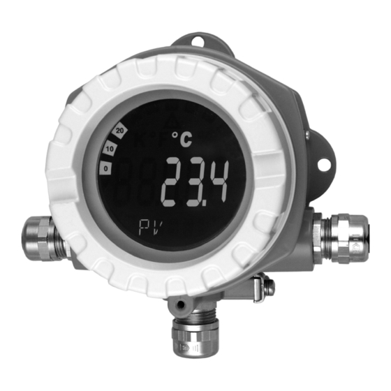
  • Page 102: Configuration

    Lors d'un accès lecture et écriture via le protocole HART on obtient le symbole de communication Affichage "Configuration verrouillée" Lors d'un verrouillage du paramétrage/de la configuration via le software et le hardware on obtient le symbole "Con- figuration verrouillée" Endress+Hauser...
  • Page 103: Configuration Sur Site

    ≤ 3,6 mA ≥ 21,0 mA Le mode défaut réglé à l'aide du cavalier devient seulement actif en cas de panne du microcontrô- leur. Remarque! Vérifier la concordance du réglage du mode défaut via le hardware et le software. Endress+Hauser...
  • Page 104: Configuration Via Protocole Hart

    Entrer le type ou modifier le réglage. Puis avec "ENTER" valider sur l'écran tactile. En activant "SEND" sur l'écran tactile toutes les valeur entrées avec le terminal portable sont transmises au système de mesure de l'appareil. En activant "HOME" sur l'écran tactile on revient au premier niveau. Endress+Hauser...
  • Page 105 • Des informations plus détaillées relatives au terminal portable HART se trouvent dans le manuel de mise en service correspondant livré avec l'appareil dans la sacoche de transport. fig. 11 : Configuration sur le terminal portable pour 'Entrée capteur' ® fig. 12 : Matrice de programmation HART Endress+Hauser...
  • Page 106: Classes De Commande Dans Le Protocole Hart

    • Commandes spécifiques à l'appareil (Device-specific Commands) Ces commandes permettent l'accès aux fonctions spécifiques à l'appareil, non standardisées ® HART . De telles commandes véhiculent des informations de terrain individuelles. Remarque! ® Au chap. 6.4.2 se trouve une liste avec toutes les fonctionnalités HART Endress+Hauser...
  • Page 107: Mise En Service

    Capteur Type de capteur Mode de raccordement Unité Sortie Valeur initiale PV Valeur finale PV Fonctions de sécurité/de maintenance Mode défaut Alarme température ambiante D'autres réglages sont possibles dans le cadre d'un ajustement spécial à l'application (voir chap. 6.4.1). Endress+Hauser...
  • Page 108: Configuration De L'appareil

    10 K Ni1000 -60 °C 150 °C 10 K Edison Copper Winding Cu10 -100 °C 260 °C 10 K No. 15 SAMA Pt100 -100 °C 700 °C 10 K Edison Curve No. 7 Ni120 -70 °C 270 °C 10 K Endress+Hauser...
  • Page 109 TYPE CAPTEUR. Température externe Entrée du point de référence externe. Entrée : -40,00 à 85,00 °C (°C, °F, K) 0 °C Remarque! La fonction est seulement active lors de la sélection "externe" dans la fonction POINT DE REFERENCE. Endress+Hauser...
  • Page 110 Entrée : Adresse HART du transmetteur de température : d'appareil 0 à 15 Remarque! Pour les adresses > 0 le transmetteur de température est en mode Multidrop et la sortie analogique est fixée à 4 mA. L'adresse d'appareil est affichée pour le mode Multidrop Endress+Hauser...
  • Page 111 • On Si la température mesurée correspond à une valeur de sortie < 3,8 mA ou > 20,5 mA, une erreur est signalée (voir "Mode défaut"). Filtre réseau Sélection du filtre de réseau • 50 Hz • 60 Hz Endress+Hauser...
  • Page 112 Lors d'un retour aux réglages usine, c'est la valeur par défaut qui est notée -9999,99. La valeur de process min. est modifiée lors de l'accès écriture à la valeur de process actuelle. Lors d'un retour aux réglages usine, c'est la valeur par défaut qui est notée +9999,99. Endress+Hauser...
  • Page 113 Certificats Affichage des agréments de l'appareil Appareil ® Affichage des informations permettant l'identification de l'appareil HART Fabricant Marque du fabricant : Endress+Hauser (=17) Type d'appareil Désignation du type de l'appareil : TMT142 Date Utilisation individuelle de ce paramètre Révision hardware Etat de révision des composants électroniques de l'appareil...
  • Page 114 Write final assembly number Common practice Write primary variable damping value Write primary variable range values Reset configuration changed flag Enter/Exit fixed primary variable current mode Perform master reset Write primary variable units Read additional device status Write number of response preambles Endress+Hauser...
  • Page 115 0 x 02 présence d'avertissement/d'alarmes Device Operating Mode toujours 0 Remarque! Le composant système Fieldgate FXA520 d'Endress+Hauser permet l'étalonnage, le diagnostic et le ® paramétrage à distance des appareils HART raccordés, par ex. un message est automatiquement envoyé par e-mail ou SMS. L'appareil exploite pour le diagnostic les 4 premiers bytes de HART-Cmd #48.
  • Page 116: Maintenance

    Maintenance TMT142 Classification d'erreur voir chap. 9.2 Messages erreur. Remarque! ® Le séparateur intelligent RN221N avec diagnostic HART d'Endress+Hauser communique ® cycliquement avec les appareils HART raccordés et signale les informations de diagnostic par le biais d'un contact inverseur. Maintenance L'appareil ne nécessite en principe aucune maintenance particulière.
  • Page 117: Suppression Des Défauts

    Les différents modes ont la signification suivante : F: défaut, C : appareil en mode service, M : maintnance néces- ® saire, S : Out of Specification, * : en fonction du mode (F ou M). voir aussi chapitre 6.4.2 Commandes HART supportées Endress+Hauser...
  • Page 118: Détection De Corrosion

    à afficher à nouveau la valeur de sortie analogique correcte. Si la tension d'alimentation est trop faible, la valeur de la sortie analogique passe à nouveau sur ≤ 3,6 mA. On évite ainsi que l'appareil n'affiche en permanence une valeur de sortie analogique erronée. Endress+Hauser...
  • Page 119: Erreur D'application Sans Messages

    Mauvais RTD configuré Modifier la fonction TYPE CAPTEUR Raccordement du capteur (2 fils) Vérifier le raccordement du capteur Résistance de ligne du capteur (2 fils) n'a Compenser la résistance de ligne pas été compensée Offset mal réglé Vérifier l'offset Endress+Hauser...
  • Page 120: Erreur D'application Pour Raccordement Tc

    Type de thermocouple (TC) mal paramétré Modifier la fonction TYPE CAPTEUR Point de référence mal réglé voir chap. "Description des fonctions" Offset mal réglé Vérifier l'offset Parasites au-dessus du filament soudé dans Utiliser un thermocouple pour lequel le le tube protecteur (couplage de tensions filament n'est pas soudé parasites) Endress+Hauser...
  • Page 121: Pièces De Rechange

    3 x entrée de câble NPT1/2" avec bornier + 1 bouchon aveugle 3 x entrée de câble M20x1,5 avec bornier + 1 bouchon aveugle Entrée de câble M20x1,5 + M24x1,5 avec bornier + 1 bouchon aveugle Version Standard ⇐ Référence TMT142G- Endress+Hauser...
  • Page 122 51004387 Adaptateur entrée de câble M20x1,5 sur NPT 1/2" Sans N° 51004454 Support affichage TMT142 Sans N° 51004915 Adaptateur M20x1,5 externe/ M24x1,5 interne VA Sans N° 51007995 Etrier de montage inox pour tubes 1,5" - 3,3" (v. chap. 3.3.2) Endress+Hauser...
  • Page 123: Retour De Matériel

    • Terminal portable HART DXR375 (from OS4.6) ® • Readwin 2000 (à partir de version 1.17.0.0) • AMS (à partir de version 5.0) • PDM (à partir de version 5.1) • Fieldcare, version à partir de 2.01.00 01.03.03, 12/2006 SW modifications interne Endress+Hauser...
  • Page 124: Caractéristiques Techniques

    • Résistance de capteur max. 10 kΩ (si la résistance de capteur > à 10 kΩ, message erreur selon NAMUR NE 89) Tensions (mV) Capteur millivolt (mV) -20 à 100 mV 5 mV Imprécisions croissantes pour des températures < 300 °C (572 °F) Endress+Hauser...
  • Page 125: Grandeurs De Sortie

    1,0 K typ. 0,5 K 0,02% S, B, R typ. 2,0 K typ. 1,0 K 0,02% Les % se rapportent à l'étendue de mesure réglée. Précision de mesure = précision de mesure digitale + D/A seulement avec option "Advanced Electronics" Endress+Hauser...
  • Page 126: Reproductibilité

    ≤ ±0,005%/V écart de 24 V, rapporté à la fin d'échelle Effet de la tension d'alimentation ≤ 0,1K/an ou ≤0,05%/an Stabilité à long terme Indications sous conditions de référence. Les % se rapportent à l'étendue de mesure réglée. La plus grande valeur est valable. Endress+Hauser...
  • Page 127: Effet De La Température Ambiante (Dérive De Température)

    Δϑ = écart de la température ambiante par rapport à la condition de référence Erreur de tout le point de mesure = erreur de mesure max. possible + erreur sonde de température Effet point de soudure froide Pt100 DIN CEI 751 Cl. B (point de référence interne pour thermocouples TC) Endress+Hauser...
  • Page 128: Conditions Environnantes

    13 : Indications en mm (indications en inches entre parenthèses) • Module de l'électronique et zone de raccordement séparés • Affichage orientable par pas de 90° Poids • env. 1,6 kg (boîtier aluminium) • env. 4,2 kg (boîtier inox) Endress+Hauser...
  • Page 129: Matériaux

    Marque CE L'appareil satisfait les exigences légales des directives CE. Par l'apposition du sigle CE, Endress+Hauser certifie que l'appareil a passé les différents contrôles avec succès. Agrément Ex Votre agence E+H vous renseignera sur les versions Ex actuellement disponibles (ATEX, FM, CSA, etc.).
  • Page 130: Annexe

    Le calcul de δ se base sur l'écart entre la température réelle T et la température calculée en (4) (5) : En introduisant δ dans l'équation, il est possible de calculer la résistance pour des valeurs de tem- pérature positives avec une grande précision (6) : Endress+Hauser...
  • Page 131 (8) fournit le résultat suivant (10) : (11) (12) L'appareil accepte l'indication des coefficients comme α, β, δ et A, B, C. Les indications relatives aux coefficients peuvent être demandées aux fabricants de capteurs. Endress+Hauser...
  • Page 132: Polynome Rtd

    10. Pour mémoriser toutes les données dans des fichiers, utiliser Data → Save ou Data → Save as... 11. Pour utiliser cette fonctionnalité du transmetteur, cliquer sur OK (les données sont reprises ® dans ReadWin 2000 übernommen) et démarrer la transmission à l'appareil. Endress+Hauser...
  • Page 133: Index

    Réglage du mode défaut ..... . . 103 Résistance de communication de 250 Ohm ... 100 Endress+Hauser...
  • Page 134 TMT142 Index Endress+Hauser...
  • Page 136 www.endress.com/worldwide BA191R/09/a3/12.06 51009174 FM+SGML6.0 ProMoDo...

Table des Matières