Endress+Hauser iTEMP HART TMT142 Mode D'emploi
Masquer les pouces
Voir aussi pour iTEMP HART TMT142:
- Manuel de mise en service (136 pages) ,
- Consignes de sécurité (21 pages) ,
- Information technique (17 pages)
Table des Matières
Publicité
Les langues disponibles
Les langues disponibles
Liens rapides
KA00222R/09/A3/13.15
71287908
6
Products
Brief operating instructions
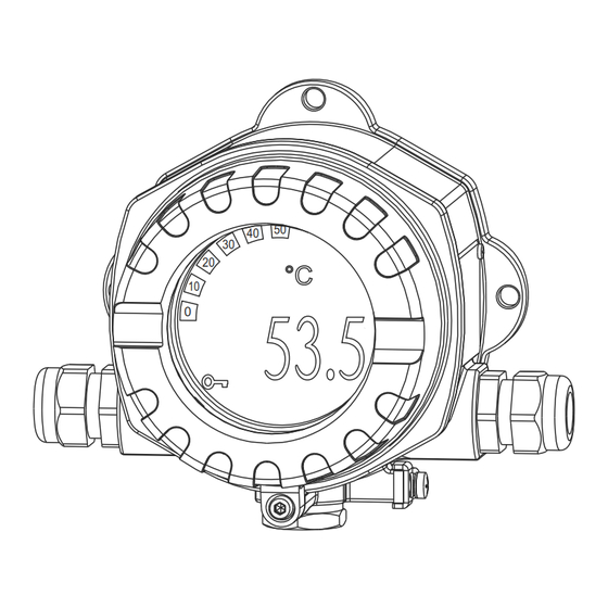
iTEMP HART® TMT142
Temperature field transmitter
30
20
10
0
;
Temperaturfeldtransmitter (ab Seite
<
Temperature field transmitter (from page 17)
=
Transmetteur de température de terrain (à partir de page 32)
Solutions
50
40
°C
53.5
3
Services
)
Publicité
Table des Matières

Manuels Connexes pour Endress+Hauser iTEMP HART TMT142


Sommaire des Matières pour Endress+Hauser iTEMP HART TMT142
- Page 1 Products Solutions Services KA00222R/09/A3/13.15 71287908 Brief operating instructions iTEMP HART® TMT142 Temperature field transmitter °C 53.5 Temperaturfeldtransmitter (ab Seite < Temperature field transmitter (from page 17) Transmetteur de température de terrain (à partir de page 32)
- Page 2 Zugehörige Dokumentation finden TMT142 HART® Zugehörige Dokumentation finden Order code 00X00-XXXX0XX0XXX Ser. No.: X000X000000 TAG No.: XXX000 Serial number www.endress.com/deviceviewer Endress+Hauser Operations App...
-
Page 3: Table Des Matières
4.3 Anzeige- und Bedienelemente ............... . 14 Diese Anleitung ist eine Kurzanleitung, sie ersetzt nicht die zum Lieferumfang gehörende Betriebsanleitung. Ausführliche Informationen entnehmen Sie der Betriebsanleitung und den weiteren Dokumentationen. Für alle Geräteausführungen verfügbar über: • Internet: www.endress.com/deviceviewer • Smartphone/Tablet: Endress+Hauser Operations App... -
Page 4: Sicherheitshinweise
Sicherheitshinweise TMT142 HART® Sicherheitshinweise WARNUNG Elektrische Schläge können zum Tod oder zu schweren Körperverletzungen führen. ‣ Gehen Sie mit äußerster Vorsicht vor, falls Sie Kabel und Klemmen berühren. Wenn das Gerät/die Messeinrichtung in einer Hochspannungsumgebung installiert wird und es zu einer Störung oder einem Installationsfehler kommt, kann an den Anschlussklemmen oder dem Gerät/der Messeinrichtung selbst Hochspannung anliegen Bestimmungsgemäße Verwendung... -
Page 5: Sicherheitszeichen Und -Symbole
TMT142 HART® Sicherheitshinweise den nationalen Normen einzuhalten. Dem Gerät liegt eine separate Ex-Dokumentation bei, die ein fester Bestandteil der gesamten Anleitung ist. Die darin aufgeführten Installationsvorschrif- ten, Anschlusswerte und Sicherheitshinweise sind zu beachten. Die Dokumentationsnummer dieser Anleitung (XA) ist ebenfalls auf dem Typenschild angegeben. Störsicherheit Die Messeinrichtung erfüllt die allgemeinen Sicherheitsanforderungen gemäß... -
Page 6: Montage
Montage TMT142 HART® Montage Montage auf einen Blick Das Gerät kann bei Verwendung stabiler Sensoren direkt auf den Sensor montiert werden. Für die abgesetzte Montage an einem Rohr steht ein Montagehalter zur Verfügung. 121 (4.8) 121 (4.8) A0007952 Abb. 1: Direkte Wand- oder Rohrmontage (Abmessungen in mm (in)) Montagebedingungen 2.2.1 Abmessungen •... -
Page 7: Montage
TMT142 HART® Montage Montage 2.3.1 Direkte Wandmontage Zur direkten Wandmontage des Gerätes gehen Sie wie folgt vor: • 2 Löcher bohren. Bohrschablone und Bohrabstand Abb. 1 • Gerät an der Wand mit 2 Schrauben (M6) anbringen. 2.3.2 Rohrmontage Der Montagehalter ist geeignet für Rohre mit einem Durchmesser zwischen 1,5 in und 3,3 in. Zur Montage des Gerätes an ein Rohr gehen Sie wie folgt vor ... -
Page 8: Verdrahtung
‣ Anschluss im Ex-Bereich nur mit zertifizierten Geräten (als Option erhältlich). Entsprechende Hinweise und Anschlussbilder in den spezifischen Ex-Zusatzdokumentatio- nen zu dieser Betriebsanleitung beachten. Bei Fragen steht Ihnen Ihre Endress+Hauser Vertretung gerne zur Verfügung. A0007959 Abb. 2: Öffnen des Feldtransmitters Bei der Verdrahtung des Gerätes grundsätzlich wie folgt vorgehen:... - Page 9 TMT142 HART® Verdrahtung Die Leitungen durch die Öffnung der Kabelverschraubungen führen. Die Leitungen gemäß Abb. 3 am Klemmenblock anschließen. Nach erfolgter Verdrahtung die Schraubklemmen der Anschlüsse festdrehen. Die Kabel- verschraubungen (Pos. 5) wieder anziehen. Dabei auch Kap. 3.4 beachten. Die Elektronikeinheit (Pos. 4) anschrauben, gegebenenfalls das Display mit Verdrehsiche- rung (Pos.
-
Page 10: Verdrahtung Auf Einen Blick
Verdrahtung TMT142 HART® Verdrahtung auf einen Blick 3.1.1 Klemmenbelegung Sensor 11...40 V 11...30 V Ex 4...20 mA HART® - Signal Sensor 2-Leiter 3-Leiter 4-Leiter A0026193-DE Abb. 3: Verdrahtung des Feldtransmitters - Klemmenbelegung ESD - Electrostatic discharge Klemmen vor elektrostatischer Entladung schützen. Ein Nichtbeachten kann zur Zerstörung von Teilen der Elektronik führen. - Page 11 TMT142 HART® Verdrahtung Anschlussmöglichkeit mit Endress+Hauser Speisegerät RN221N °C 52.5 SFX100, DXR375 Commubox FXA 191 ReadWin® 2000, FieldCare A0026195 ® HART -Anschluss mit Endress+Hauser Speisegerät RN221N Anschlussmöglichkeit mit anderen Speisegeräten ³ 250 Ω Commubox °C 52.5 FXA 191 SFX100, DXR375 ReadWin®...
-
Page 12: Schirmung Und Potenzialausgleich
Verdrahtung TMT142 HART® Schirmung und Potenzialausgleich Bei der Installation ist zu beachten: Werden geschirmte Leitungen verwendet, muss die Schirmung der Ausgangsseite (Ausgangs- signal 4 bis 20 mA) und die Schirmung der Sensoranschlussseite das gleiche Potenzial haben! In Anlagen mit starken elektromagnetischen Feldern wird eine Schirmung aller Leitungen mit niederohmiger Anbindung an Erde empfohlen. -
Page 13: Anschlusskontrolle
TMT142 HART® Verdrahtung Anschlusskontrolle Führen Sie nach der elektrischen Installation des Gerätes folgende Kontrollen durch: Gerätezustand und -spezifikationen Hinweise Sind Gerät oder Kabel beschädigt (Sichtkontrolle)? Elektrischer Anschluss Hinweise Ist die Kabeltypenführung einwandfrei getrennt - Ohne Schleifen und Überkreuzungen? Sind die montierten Kabel von Zug entlastet? Ist die Klemmenbelegung richtig? Vergleichen Sie das Anschlussschema siehe Anschlussschema am Gehäuse vom Klemmenblock oder ... -
Page 14: Inbetriebnahme
Inbetriebnahme TMT142 HART® Inbetriebnahme Installations- und Funktionskontrolle Vor der ersten Inbetriebnahme vergewissern Sie sich bitte, dass: • das Gerät korrekt montiert wurde und • der elektrische Anschluss richtig ist. Einschalten des Messgerätes Falls Sie die Abschlusskontrollen durchgeführt haben, schalten Sie nun die Versorgungsspan- nung ein. - Page 15 TMT142 HART® Inbetriebnahme Anzeigesymbole Pos.-Nr. Funktion Beschreibung Bargraphanzeige In 10%-Schritten mit Marken für Messbereichsunter-/überschreitung. Die Bargraphanzeige blinkt bei Auftreten eines Fehlers. Anzeige ’Achtung’ Diese Anzeige erscheint bei Fehler oder Warnung Einheitenanzeige K, °F, °C, % Einheitenanzeige für den jeweilig angezeigten Messwert Messwertanzeige Anzeige des Messwerts.
- Page 16 Inbetriebnahme TMT142 HART® ESD - Electrostatic discharge Klemmen vor elektrostatischer Entladung schützen. Ein Nichtbeachten kann zur Zerstörung von Teilen der Elektronik führen. Die Jumper J1, J2 und J3 für die Hardwareeinstellung befinden sich auf dem Elektronikmodul. Für die Einstellung der Jumper schrauben Sie den Gehäusedeckel ab ( Abb. 2) und ziehen Sie gegebenenfalls das Display ab.
- Page 17 TMT142 HART® How to find the documentation for your device How to find the documentation for your device Order code 00X00-XXXX0XX0XXX Ser. No.: X000X000000 TAG No.: XXX000 Serial number www.endress.com/deviceviewer Endress+Hauser Operations App...
- Page 18 These Instructions are Brief Operating Instructions; they are not a substitute for the Operating Instructions pertaining to the device. For detailed information, refer to the Operating Instructions and other documentation. Available for all device versions via: • Internet: www.endress.com/deviceviewer • Smart phone/Tablet: Endress+Hauser Operations App...
-
Page 19: Safety Instructions
TMT142 HART® Safety instructions Safety instructions WARNING Electric shocks can cause death or serious injury ‣ Proceed with extreme caution when working with cables and terminals. If the device/measuring system is installed in a high-voltage environment and a malfunction or installation error occurs, high voltage can be present at the terminals or the device/measuring system itself. -
Page 20: Electromagnetic Compatibility
Safety instructions TMT142 HART® with the installation instructions, ratings and safety instructions as listed in this supplementary documentation is mandatory. The documentation number of this document (XA) is also indicated on the nameplate. Electromagnetic compatibility The measuring system complies with the general safety requirements in accordance with EN 61010 and the EMC requirements of IEC/EN 61326 and NAMUR Recommendations NE 21, NE 43 and NE 89. -
Page 21: Installation Instructions
TMT142 HART® Installation instructions Installation instructions Quick installation guide If stable sensors are used, the device can be fitted directly to the sensor. For remote mounting to a stand pipe, a mounting kit is available. 121 (4.8) 121 (4.8) A0007952 Fig. -
Page 22: Installation Instructions
Installation instructions TMT142 HART® Installation instructions 2.3.1 Direct wall mounting Proceed as follows to mount the device directly on wall: • Drill 2 holes. Drill template and drill hole distance Fig. 1. • Attach the device to the wall with 2 screws (M6). 2.3.2 Pipe installation The mounting bracket is suited for pipes with a diameter between 1.5 in to 3.3 in. -
Page 23: Wiring
Only certified devices (optionally available) may be connected in the hazardous area. Observe corresponding notes and wiring diagrams in the Ex-specific supplement to these Operating Instructions. If you have any questions, please do not hesitate to contact your Endress+Hauser representative. A0007959 Fig. 2: Opening the field transmitter For wiring the device proceed as follows: Remove the cover clamp (item 1). -
Page 24: Quick Wiring Guide
Wiring TMT142 HART® Make sure that the terminal screws are tight. Re-seal the cable gland by screwing the cover back on. In doing so, also pay particular attention to Chap. 3.4. On completion of the wiring, screw on the electronics module (item 4) again, plug on the display with twist protection (item 3) again if applicable and screw the housing cover together with the O-ring (item 2) down again. -
Page 25: Connecting The Measuring Unit
2-wire supply lines. For connection hints, please take special notice of the documentation supplied by the HART® Communication Foundation, specifically HCF LIT 20: “HART, a technical overview”. Connection using the Endress+Hauser power supply RN221N °C 52.5 SFX100, DXR375... - Page 26 Wiring TMT142 HART® ³ 250 Ω Commubox °C 52.5 FXA 191 SFX100, DXR375 ReadWin® 2000, FieldCare A0026194 ® HART connection using other power supplies...
-
Page 27: Shielding And Potential Equalization
TMT142 HART® Wiring Shielding and potential equalization Please take note when installing the device: If screened (shielded) cables are used then the shielding connected to the output (output signal 4 to 20 mA) must be at the same potential as the shielding at the sensor connection! When operating in plants with high electromagnetic fields, it is recommended that all cables be shielded using a low ohm ground connection. -
Page 28: Connection Check
Wiring TMT142 HART® Connection check After the electrical installation of the device, always perform the following final checks: Device condition and specification Hint Are the device or the cables damaged (visual check)? Electrical connection Hint Is the cable/conduit installation correctly separated, with no loops or crossovers? Are the cables’... -
Page 29: Commissioning
TMT142 HART® Commissioning Commissioning Function check Prior to commissioning, please ensure that: • The device has been mounted correctly and • the electrical connection is correct. Switching on the measuring device Once the final checks have been successfully completed, it is time to switch on the supply voltage. - Page 30 Commissioning TMT142 HART® Pos. no. Function Description Measured value display Measured value display. If a warning is present this display (0.81" / 20.5 mm character size) alternates between the measured value and the warning code. In the event of an error, the error code is dispalyed instead of the measured value.
- Page 31 TMT142 HART® Commissioning Setup or configuration hardware lock using jumper J1 TRANSMITTER SECURITY Setup/configuration locked Setup/configuration unlocked The hardware setup/configuration lock has priority over the software setup. Setup hardware fault conditioning using jumper J2 FAILURE MODE 3.6 mA 21.0 mA The failure mode conditioning setup using the jumper is only active when the microcontroller fails.
- Page 32 Comment trouver la documentation relative à votre appareil TMT142 HART® Comment trouver la documentation relative à votre appareil Order code 00X00-XXXX0XX0XXX Ser. No.: X000X000000 TAG No.: XXX000 Serial number www.endress.com/deviceviewer Endress+Hauser Operations App...
- Page 33 Les informations détaillées figurent dans le manuel de mise en service et les autres documentations. Disponibles pour toutes les versions d' a ppareil via : • Internet : www.endress.com/deviceviewer • Smartphone/tablette : Endress+Hauser Operations App...
-
Page 34: Conseils De Sécurité
Conseils de sécurité TMT142 HART® Conseils de sécurité AVERTISSEMENT Les décharges électriques peuvent entraîner la mort ou de graves dommages corporels. ‣ Procédez avec une extrême prudence lorsque vous touchez des câbles et bornes. Si l' a ppareil/l' e nsemble de mesure est installé dans un environnement sous haute tension et si l' o n observe un défaut ou une erreur d' i nstallation, il se peut que les bornes de raccordement ou l' a ppareil/l' e nsemble de mesure soient sous haute tension. -
Page 35: Immunité Aux Interférences
TMT142 HART® Conseils de sécurité valeurs de raccordement et conseils de sécurité qui y figurent sont à respecter. Le numéro de cette documentation (XA) figure également sur la plaque signalétique. Immunité aux interférences L' e nsemble de mesure satisfait aux exigences de sécurité selon EN 61010 et les exigences CEM selon CEI/EN 61326 ainsi que les recommandations NAMUR NE 21, NE 43 et NE 89. -
Page 36: Montage
Montage TMT142 HART® Montage Montage en bref Si les capteurs utilisés sont stables, le transmetteur peut y être directement associé. Un étrier de fixation est disponible pour le montage sur colonne. 121 (4.8) 121 (4.8) A0007952 Fig. 1: Montage direct sur mur ou sur colonne (dimensions en mm (in)) Conditions de montage 2.2.1 Dimensions •... -
Page 37: Montage
TMT142 HART® Montage Montage 2.3.1 Montage mural direct Pour un montage mural direct de l' a ppareil, procédez de la façon suivante : • Percer 2 trous. Gabarit et écart des perçages Fig. 1 • Fixer l' a ppareil au mur à l' a ide de 2 vis (M6). 2.3.2 Montage sur mât L' é... -
Page 38: Câblage
Seuls des appareils certifiés (disponibles en option) peuvent être raccordés en zone Ex. Respectez les consignes et schémas contenus dans les documentations Ex en supplément de ce manuel. Pour tout renseignement complémentaire, contactez votre agence Endress+Hauser. A0007959 Fig. 2: Ouverture du transmetteur de terrain Pour le câblage de l' a ppareil, procédez de la façon suivante :... - Page 39 TMT142 HART® Câblage Faire passer les câbles à travers l' o uverture des presse-étoupe. Relier les câbles au bornier conformément à fig. 3. Après le câblage, serrer les bornes de raccordement. Serrer à nouveau les presse-étoupe (Pos. 5). Tenir également compte du chap. 3.4. Visser l' é...
-
Page 40: Câblage En Bref
Câblage TMT142 HART® Câblage en bref 3.1.1 Occupation des bornes Sensor 11...40 V 11...30 V Ex 4...20 mA HART® - Signal Sensor 2-Leiter 3-Leiter 4-Leiter A0026193-DE Fig. 3: Câblage du transmetteur de terrain - Occupation des bornes ESD - Electrostatic discharge Protéger les bornes contre les décharges électrostatiques. - Page 41 TMT142 HART® Câblage Possibilité de raccordement avec alimentation Endress+Hauser RN221N °C 52.5 SFX100, DXR375 Commubox FXA 191 ReadWin® 2000, FieldCare A0026195 Raccordement HART® avec alimentation Endress+Hauser RN221N Possibilités de raccordement avec d'autres alimentations ³ 250 Ω Commubox °C 52.5 FXA 191...
-
Page 42: Blindage Et Compensation De Potentiel
Câblage TMT142 HART® Blindage et compensation de potentiel Lors de l' i nstallation, tenir compte des points suivants : Si des câbles blindés sont utilisés, il faut que le blindage côté sortie (signal de sortie 4 à 20 mA) et le blindage côté capteur aient le même potentiel ! Dans les installations avec des champs magnétiques puissants, il est recommandé... -
Page 43: Contrôle Du Raccordement
TMT142 HART® Câblage Contrôle du raccordement Après l' i nstallation électrique du transmetteur, procéder aux contrôles suivants : Etat et spécifications de l'appareil Remarques L' a ppareil ou le câble sont-ils endommagés (contrôle visuel) ? Raccordement électrique Remarques Les types de câble sont-ils correctement séparés - sans boucles ni croisements ? Les câbles installés sont-ils libres de toute traction ? L' o ccupation des bornes est-elle correcte ? Comparer le schéma de... -
Page 44: Mise En Service
Mise en service TMT142 HART® Mise en service Contrôle de l'installation et du fonctionnement Avant la première mise en service, assurez-vous que : • l' a ppareil a été monté correctement et • le raccordement électrique est correct. Mise sous tension de l'appareil de mesure Après avoir effectué... - Page 45 TMT142 HART® Mise en service Symboles d' a ffichage Pos. Fonction Description Affichage bargraph En pas de 10% avec marques pour les dépassements par excès ou défaut des seuils. L' a ffichage bargraph clignote lors de l' a pparition d' u n défaut. Affichage "Attention"...
- Page 46 Mise en service TMT142 HART® ESD - Electrostatic discharge Protéger les bornes contre les décharges électrostatiques. Un non-respect peut entraîner la destruction de l' é lectronique. Les cavaliers J1, J2 et J3 pour le réglage du hardware se trouvent sur le module électronique. Pour le réglage des cavaliers, dévisser le couvercle du boîtier (...
- Page 47 TMT142 HART® Mise en service...
- Page 48 www.addresses.endress.com...