Publicité

Les langues disponibles

Les langues disponibles

Liens rapides

DE | EN | FR
A-Digit 50 / 75
BEDIENUNGSANLEITUNG
USER MANUAL
MODE D'EMPLOI
www.geo-fennel.de
www.geo-fennel.com
www.geo-fennel.fr

Publicité

Chapitres

Table des Matières
loading

Sommaire des Matières pour geo-FENNEL A-Digit 50

  • Page 1 DE | EN | FR A-Digit 50 / 75 BEDIENUNGSANLEITUNG USER MANUAL MODE D‘EMPLOI www.geo-fennel.de www.geo-fennel.com www.geo-fennel.fr...
  • Page 2: Table Des Matières

    Sehr geehrter Kunde, vielen Dank für das Vertrauen, welches Sie uns beim Erwerb Ihres neuen geo-FENNEL-Gerätes ent- gegengebracht haben. Dieses hochwertige Qualitätsprodukt wurde mit größter Sorgfalt produziert und qualitätsgeprüft. Die beigefügte Anleitung wird Ihnen helfen, das Gerät sachgemäß zu bedienen. Bitte lesen Sie ins- besondere auch die Sicherheitshinweise vor der Inbetriebnahme aufmerksam durch.
  • Page 3: Funktionen

    Genauigkeit Libellen 0,057° (1mm/m) Betriebstemperatur -10°C - +50° C Stromversorgung 2 x AAA Aklkaline Betriebsdauer 100 h Länge (aufgeklappt): A-Digit 50 991 mm A-Digit 75 1410 mm Gewicht 0,9 kg (1,1 kg) FUNKTIONEN • Winkelmessung • Zusatzwinkel • Einfacher Gehrungswinkel •...
  • Page 4: Bedienelemente

    BEDIENELEMENTE 1. Horizontallibelle 2. Vertikallibelle 3. HOLD / SUP (Kombi-Funktions-Taste) 4. ON/OFF (Ein/Aus-Taste) 5. Einstellbarer Winkelarm 6. Arretierungsschraube 7 . MITRE (Kombi-Winkel-Modus-Taste)
  • Page 5: Display

    DISPLAY SYMBOLERKLÄRUNG 1. Batteriezustandsanzeige 2. SUP (Gegenwinkel-Modus) 3. HOLD (Halten-Modus) 4. BVL (Schrägkantenwinkel-Anzeige) 5. MTR (Gehrungswinkel-Anzeige) 6. CNR (Eck-Winkel-Anzeige) 7 . SPR (Feder-Anzeige) 8. Winkelanzeige BEDIENUNG EIN /AUSSCHALTEN Taste ON/OFF kurz drücken, um das Gerät mit Hintergrundbeleuchtung einzuschalten. Nach dem Einschalten zeigt das Gerät den Winkel zwischen den Schenkeln in Grad (°) an. Taste ON/OFF 2 Sekunden gedrückt halten, um das Gerät wieder auszuschalten.
  • Page 6: Anzeige Drehen

    ANZEIGE DREHEN Gerät einschalten und Taste ON/OFF kurz drücken – nun kann die Anzeige über Kopf abgelesen werden. Taste erneut kurz drücken, um die Anzeige wieder in Normalposition zu bringen. GERÄT KALIBRIEREN Der Nullpunkt des Gerätes kann jederzeit neu kalibriert werden. Eine Kalibrierung sollte insbesondere vor wichtigen Messungen vorgenommen werden.
  • Page 7 KOMBI-WINKEL-MODUS Zum Schneiden von Kombinationswinkeln (Kranzleisten) benutzen Sie den Kombi-Winkel-Modus. Dafür muss der Wert von Feder- (SPR) sowie der Eckwinkel im Gerät gespeichert werden. Dieses berechnet dann die Gehrungs- und Schrägwinkel, die zum Einstellen einer Kombi-Gehrungssäge erforderlich sind. Bitte beachten: Wenn Sie den Federwinkel des zu bearbeitenden Gegenstandes nicht kennen, sollte dieser vorher ermittelt werden (siehe Zusatzwinkel).
  • Page 8: Sicherheitshinweise

    Schritt 4a: Wenn der zuletzt gespeicherte CNR-Wert geändert werden muss, stellen Sie den erforderlichen Winkel durch Einstellen der Arme ein. Um den Winkel zu speichern, halten Sie die Taste „MITRE“ kurz ge- drückt. Der angezeigte Winkel sowie CNR blinken einmal auf. Dieser Winkel ist nun als Eckwinkel (CNR) gespeichert.
  • Page 9: Garantie

    WARN- UND SICHERHEITSHINWEISE · Richten Sie sich nach den Anweisungen der Bedienungsanleitung. · Anleitung vor Benutzung des Gerätes lesen. · Niemals das Gehäuse öffnen. Reparaturen nur vom autorisierten Fachhändler durchführen lassen · Keine Warn- oder Sicherheitshinweise entfernen · Gerät nicht in Kinderhände gelangen lassen. CE-KONFORMITÄT Das Gerät hat das CE-Zeichen gemäß...
  • Page 10 Dear customer, Thank you for your confidence in us having purchased a geo-FENNEL instrument. This manual will help you to operate the instrument appropriately. Please read the manual carefully - particularly the safety instructions. A proper use only guarantees a longtime and reliable operation.
  • Page 11: Features

    0,057° (1mm/m) Operating temperature -10°C - +50° C Power supply 2 x AAA Aklkaline Operating time 100 h Length (unfolded): A-Digit 50 991 mm A-Digit 75 1410 mm Weight 0,9 kg (1,1 kg) FEATURES • Angle measurement • Supplement angle •...
  • Page 12: Operating Elements

    OPERATING ELEMENTS 1. Horizontal vial 2. Vertical vial 3. HOLD/SUP (combined function key) 4. ON/OFF button 5. Adjustable arm 6. Locking screw 7 . MITRE (combined angle mode key)
  • Page 13: Display

    DISPLAY SYMBOLS 1. Battery status indicator 2. SUP (supplemental angle mode) 3. HOLD (hold mode) 4. BVL (bevel display) 5. MTR (basic mitre angle display) 6. CNR (corner angle display) 7 . SPR (spring angle display) 8. Angle display OPERATION POWER ON/OFF THE UNIT Press the ON/OFF button to power on the unit and the background illumination.
  • Page 14: Hold Function

    INVERT THE DISPLAY Power on the instrument and press the ON/OFF button briefly – now the display can be read overhead. Press the button briefly again to return to the standard display indication. RE-CALIBRATE The zero point can be re-calibrated at any time. The instrument should be re-calibrated especially before carrying out important measurements.
  • Page 15 COMPOUND ANGLE MODE For compound angles (cuts for crown molding) you will need to enter into the compound angle mode and save the spring angle and the corner angle values into the memory. The unit will then calculate the mitre angle and bevel angle values necessary to set up a compound mitre saw.
  • Page 16: Safety Notes

    Step 4a: If the CNR angle value stored needs to be changed set up the arms to the desired angle. Then press the „MITRE“ button to save the new angle value. The indicator CNR and the saved angle will flash once to indicate that the new angle value has been stored into the memory as the corner angle value(CNR).
  • Page 17 SAFETY INSTRUCTIONS · Follow up the instructions given in the user manual. · Carefully read the instruction manual before use · Do not open the instrument housing. Repairs should be carried out by authorized workshops only. Please contact your local dealer. ·...
  • Page 18 Menu 1. Fournic avec 2. Caractéristiques 3. Alimentation en courant 4. Description 5. Écran 6. Opération 7 . Consignes de sécurité FOURNI AVEC • Lecteur d‘angle digital A-Digit 50 / A-Digit 75 • Piles • Sacoche rembourrée • Mode d‘emploi...
  • Page 19: Données Techniques

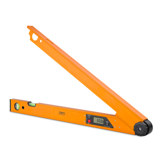
    0,057° (1mm/m) Plage de température -10°C - +50° C Alimentation en courant 2 x AAA piles alcalines Autonomie 100 h Longueur (instrument déplié): A-Digit 50 991 mm A-Digit 75 1410 mm Poids 0,9 kg (1,1 kg) CARACTÉRISTIQUES • Mesure d‘angle •...
  • Page 20 DESCRIPTION 1. Nivelle horizontale 2. Nivelle verticale 3. Bouton combiné HOLD/SUP 4. Bouton MARCHE/ARRÊT (ON/OFF) 5. Bras équerre réglable 6. Vis de fixation 7 . Bouton MITRE (mode angle combiné)
  • Page 21 ÉCRAN SYMBOLES 1. Indicateur de l‘état des piles 2. Affichage SUP (accomplément d‘angle) 3. Affichage HOLD (maintenir) 4. Affichage BVL (angle d’onglet vertical) 5. Affichage MTR (coupe d‘onglet) 6. Affichage CNR (angle de coin) 7 . Affichage SPR (angle d‘inclinaison) 8.
  • Page 22: Recalibration

    AFFICHAGE INVERSE Allumer l‘instrument et appuyer sur le bouton ON/OFF brièvement - maintenant l‘écran peut être lu du dessus. Appuyez sur le bouton encore une fois brièvement pour revenir à l‘indication d‘affichage standard. RECALIBRATION Le point zéro peut être re-calibré à tout moment. L ‘instrument doit être ré-étalonné en particulier avant d‘effectuer des mesures importantes.
  • Page 23: Coupe D'onglet Double

    COUPE D’ONGLET DOUBLE Pour des coupes d’onglet double (coupes pour les moulures de plafond), vous aurez besoin d‘entrer dans le mode coupe d’onglet double et enregistrer l‘angle d’inclinaison et les valeurs d‘angle de coin dans la mémoire. L ’appareil va alors calculer l‘angle d‘onglet et les valeurs d‘angle de biseau nécessaires pour placer la scie d’onglet combinée.
  • Page 24: Consignes De Sécurité

    Etape 4a: Si la valeur d‘angle de coin CNR stockée doit être changée mettre en place les bras à l‘angle désiré. Appuyez ensuite sur le bouton „MITRE“ pour enregistrer la nouvelle valeur d‘angle. L ‘indicateur CNR et l‘angle enregistré clignoteront une fois pour indiquer que la nouvelle valeur de l‘angle a été stockée dans la mémoire en tant que valeur d‘angle de coin (CNR).
  • Page 25: Indications D'avertissement Et De Sécurite

    INDICATIONS D‘AVERTISSEMENT ET DE SÉCURITE · Prière de respecter les instructions fournies dans le mode d’emploi du niveau. · Lire ces instructions avant d’utiliser l’instrument. · Ne jamais ouvrir soi-même le boîtier du niveau. Faire exécuter les réparations éventuelles unique- ment par un spécialiste autorisé.
  • Page 28 GmbH Technische Änderungen vorbehalten. Kupferstraße 6 All instruments subject to technical changes. D-34225 Baunatal Sous réserve de modifications techniques. Tel. +49 561 / 49 21 45 +49 561 / 49 72 34 info@geo-fennel.de 12/2014 www.geo-fennel.de Precision by tradition.

Ce manuel est également adapté pour:

A-digit 75650075

Table des Matières