Burkert 8626 Instructions De Service
Masquer les pouces Voir aussi pour 8626:
Table des Matières

Publicité

Les langues disponibles

Les langues disponibles

Liens rapides

F l u i d C o n t r o l S y s t e m s
MASS FLOW CONTROLLER
TYPE 8626
Bedienungsanleitung / Operating Instructions / Instructions de service

Publicité

Table des Matières
loading

Sommaire des Matières pour Burkert 8626

  • Page 1 F l u i d C o n t r o l S y s t e m s MASS FLOW CONTROLLER TYPE 8626 Bedienungsanleitung / Operating Instructions / Instructions de service...
  • Page 2: Table Des Matières

    MASS FLOW CONTROLLER TYP 8626 INHALT ALLGEMEINES ...................... 3 Sicherheitshinweise ....................3 Schutz gegen Beschädigung durch elektrostatische Aufladung ......3 Lieferbedingungen ....................4 Garantiebestimmungen ................... 4 SYSTEMBESCHREIBUNG ..................5 Allgemeine Funktion ....................5 Fluidische Anschlüsse .................... 6 Elektrische Anschlüsse ................... 7 2.4.
  • Page 3 DARSTELLUNGSMITTEL In dieser Betriebsanleitung werden folgende Darstellungsmittel verwendet: markiert einen Arbeitsschritt, den Sie ausführen müssen ACHTUNG! kennzeichnet Hinweise, bei deren Nichtbeachtung Ihre Gesund- heit oder die Funktionsfähigkeit des Gerätes gefährdet ist. HINWEIS kennzeichnet wichtige Zusatzinformationen, Tips und Empfehlungen Typ 8626...
  • Page 4: Allgemeines

    Sicherheitshinweise Bitte beachten Sie die Hinweise dieser Betriebsanleitung sowie die Einsatz- bedingungen und zulässigen Daten, die in den Datenblättern des Mass Flow Controllers Typ 8626 spezifiziert sind, damit das Gerät einwandfrei funktioniert und lange einsatzfähig bleibt: • Halten Sie sich bei der Einsatzplanung und dem Betrieb des Gerätes an die allgemeinen Regeln der Technik! •...
  • Page 5: Lieferumfang

    Tel. : 07940-10252 oder an Ihre Bürkert-Niederlassung. Garantiebestimmungen Bürkert gewährt auf die ordnungsgemäße Funktion des MFC Typ 8626 eine Garan- tie von einem Jahr unter der Voraussetzung, daß das Gerät bestimmungsgemäß und unter Beachtung der spezifizierten Einsatzbedingungen verwendet wird. ACHTUNG! Zur bestimmungsgemäßen Verwendung gehört insbesondere...
  • Page 6: Systembeschreibung

    SYSTEMBESCHREIBUNG Allgemeine Funktion Der Mass Flow Controller (MFC) Typ 8626 ist ein Kompaktgerät, mit dem der Massen durchfluß von Gasen geregelt wird. Er regelt einen vorgegebenen Sollwert unabhängig von Störgrößen wie Druckschwankungen oder zeitlich veränderlichen Strömungswiderständen aus (z.B. infolge Filterverschmutzung).
  • Page 7: Fluidische Anschlüsse

    Beachten Sie beim Anschließen des Gerätes in jedem Fall die Pfeilkennzeichnung auf dem Sensorblock! HINWEIS Besondere Ein- oder Auslaufstrecken sind aufgrund der integrierten Elemente zur Strömungskonditionierung nicht vorgeschrieben. Vermeiden Sie jedoch im Interesse einer optimalen Reproduzier- barkeit Winkel oder enge Biegeradien direkt am fluidischen Eingang des MFC! Typ 8626...
  • Page 8: Elektrische Anschlüsse

    Elektrische Anschlüsse Die elektrische Verbindung des MFC Typ 8626 mit Spannungsversorgung, Steue- rung usw. erfolgt durch zwei Leitungen. Diese werden über einen 7poligen Rund- steckverbinder und eine 9polige Sub-D-Steckverbindung an der Frontseite des MFC-Gehäuses mit der Elektronik verbunden. Im Abschnitt 5 “Zubehör” finden Sie die von uns empfohlenen Gegenstecker bzw.
  • Page 9 über eine spezielle Kabelverbindung und ein Modem eine Kommunikation mit dem Service im Herstellerwerk über das Telefonnetz aufzubauen. Damit kann z.B. eine schnelle Ferndiagnose bei auftretenden Problemen durchgeführt werden. Nähere Informationen zu dieser Servicemöglichkeit erhalten Sie unter der in 1.2. genannten Ansprechadresse. Typ 8626...
  • Page 10: Leuchtdioden Zur Anzeige Des Betriebszustandes

    2.4. Leuchtdioden zur Anzeige des Betriebszustandes „Power“ Die grüne LED leuchtet immer, wenn das Gerät mit Be- triebsspannung versorgt ist. „Autotune“ Die rote Kontrollampe blinkt, wenn das Gerät die sogenann- te Autotune-Routine abarbeitet. In der Routine wird der Stellgrößenbereich an die aktuellen Druckbedingungen in der Anwendung angepaßt, um die optimale Auflösung und Regeldynamik zu erreichen (s.
  • Page 11: Komponenten

    Strömungsformen. Nach einmal erfolgter Kalibrierung kann somit aus dem Sensor- signal auf den Gesamtdurchfluß im Strömungskanal rückgeschlossen werden. Im MFC Typ 8626 erfolgt die Messung im Hauptstrom , so daß eine sehr gute Dyna- mik gewährleistet ist. Durch die Anordnung des Pt-Heizwiderstandes auf einem längs zur Strömung liegenden Glaschip ist der Sensor nur in geringem Maße verschmutzungsanfällig.
  • Page 12: Regler

    2.5.2. Regler Die Verarbeitung der aktuellen Soll- und Ist-Durchflüsse und die Ansteuerung des Stellgliedes wird von einer Mikroprozessorelektronik durchgeführt. Das analoge Spannungssignal des Sensors wird von der Regelelektronik gefiltert, digitalisiert und mit Hilfe der im EEPROM hinterlegten Kalibrierkurve in einen dem Ist-Durchfluß...
  • Page 13: Proportionalventil

    Für besondere Einsatzfälle liefern wir auf Anfrage auch Geräte mit anderen Dichtmaterialien. è Berücksichtigen Sie für die Auswahl des Proportionalventils die grundlegen- den fluidischen Daten der Anlage, in welcher der MFC Typ 8626 eingesetzt wird (s. 3.1.). Nur dann werden die gewünschten Leistungsdaten sowie optimale Regeleigenschaften sichergestellt.
  • Page 14: Betriebshinweise

    BETRIEBSHINWEISE Auswahlkriterien Von entscheidender Bedeutung für die Auswahl des MFC ist: • die Verträglichkeit der mediumsberührten Teile mit den Eigenschaften des zu regelnden Gases; • die richtige Wahl des Durchflußbeiwertes, der im wesentlichen durch die Nennweite des Stellgliedes definiert wird; •...
  • Page 15 Dichte des Mediums in [kg/m ] unter Normbedingungen (1013 mbar, 273 K) Temperatur des Gases in K : Absolut drücke in [bar] vor und nach dem MFC Typ 8626 b) Sind dagegen die Druckwerte p und p am Ein- und Ausgang der Gesamt- anlage und der gewünschte Maximaldurchfluß...
  • Page 16 Die Ventilautorität ψ sollte im Interesse einer akzeptablen Betriebskennlinie der Anlage nicht unter 0.3 ... 0.5 liegen. Ist ψ ψ ψ ψ ψ kleiner als dieser Richtwert, ist der MFC Typ 8626, bzw. sein Stellglied, so überdimensioniert, daß bei voller Öffnung sein Strömungswiderstand deutlich gerin- ger ist als der der übrigen fluidischen Komponenten in der Anlage.
  • Page 17: Kalibrierung

    Transportes erkennbar sind. Im Falle von Beanstan- dungen wenden Sie sich bitte unmittelbar an unsere Serviceab- teilung (s. Seite 3). è Bauen Sie den MFC Typ 8626 nach Entfernen der Schutzkappen in das Leitungssystem ein è Vermeiden Sie Verspannungen beim Anziehen è...
  • Page 18: Betriebszustände

    Promille kommen. Betriebszustände 3.4.1 Normaler Regelbetrieb Dies ist der Betriebszustand, in dem der MFC Typ 8626 sofort nach dem Einschalten arbeitet. Im LED-Feld auf der Frontseite des Reglergehäuses leuchtet nur die grüne Power-LED. Der Durchfluß wird auf den angegebenen Sollwert mit einer hohen Dynamik ange- glichen.
  • Page 19: Autotune-Modus

    Nach einem Sollwertsprung erreicht der MFC Typ 8626 innerhalb von max. 500 ms das ±5%-Band um den neuen Sollwert und bleibt in diesem Band. Das Normsignal für den Istwertausgang ist gefiltert, um das besonders bei großen Durchflüssen starke Fluidrauschen herabzusetzen. Aus diesem Grund ist der Ist- wertausgang des MFC Typ 8626 gegenüber der hohen Dynamik der Regelung...
  • Page 20: Sollwert Nicht Erreichbar

    Anlage stark geändert haben. 3.4.3 Sollwert nicht erreichbar In diesem Zustand läuft die Regelung korrekt ab, der MFC Typ 8626 kann jedoch den vorgegebenen Sollwert nicht erreichen. Es ist eine bleibende positive Regel- abweichung (w-x) vorhanden. Dieser Betriebszustand tritt auf, wenn das Tastver- hältnis des Ventils bis nahe 100% gezogen wird, der damit erzielte Durchfluß...
  • Page 21: Sensorfehler

    Durchfluß Null) vorhanden ist. In diesem Fall ist der Sensor defekt oder es gibt Kontaktprobleme bei seiner Versorgung. Der MFC Typ 8626 schaltet automatisch in den Steuerbetrieb um, d.h. das an das Ventil ausgegebene Tastverhältnis wird linear proportional zum angelegten Sollwert gesetzt.
  • Page 22: Wartung

    Wartung Die MFC’s Typ 8626 sind bei Betrieb entsprechend den in dieser Anleitung gegebe- nen Hinweisen im Prinzip wartungsfrei. Falls nach längerem Betrieb mit einem verschmutzten Medium größere Mengen von Partikeln eingetragen wurden, kann nach Lösen der eingangsseitigen Flansch- platte (4 Inbusschrauben) das dann zugängliche Edelstahldrahtgitter gereinigt oder ersetzt werden.
  • Page 23: Störungen / Fehlersuche

    Autotune zur Anpassung an Schwingungen dem Druck, bei dem die die Betriebsbedingungen letzte Autotune ausgeführt auslösen wurde (u. U. bei werksseitiger Kalibrierung) Betriebsmedium nicht gleich Neukalibrierung beim Kalibriermedium und Hersteller für das thermische Eigenschaften Betriebsmedium beider sehr unterschiedlich Typ 8626...
  • Page 24: Zubehör

    ZUBEHÖR Artikel Best.-Nr. Rundstecker 7-polig Fa. Tuchel 646138 Sub-D-Buchse 9-polig IP65 917623 Rundstecker 7-polig Fa. Tuchel, mit 3 m Kabel, 784725 einseitig konfektioniert Sub-D-Buchse 9-polig IP65, mit 3 m Kabel, 784726 einseitig konfektioniert Geeignetes Zubehör für den fluidischen Anschluss des MFC finden Sie unter Typ 1013 im Bürkert Zubehör-Katalog.
  • Page 25 NOTIZEN Typ 8626...
  • Page 26 MASS FLOW CONTROLLER TYPE 8626 CONTENTS: GENERAL NOTES Safety notes Important for handling Scope of delivery Guarantee conditions SYSTEM DESCRIPTION Working principle Fluidic connections Electrical connections LEDs for display of operating state Components 2.5.1 Sensor 2.5.2 Control electronics 2.5.3 Proportional valve 2.5.4...
  • Page 27 The following signs are used in this operating manual: marks a work-step that you must execute ATTENTION! marks information which, if ignored, can endanger your health or the functionability of the equipment. marks important additional information, tips and NOTE recommendations Type 8626...
  • Page 28: General Notes

    Please observe the information in this operating manual and also the conditions of use and the permissible data specified in the data sheets of the Mass Flow Controller Type 8626, in order that the equipment works properly and has a long service life: •...
  • Page 29: Scope Of Delivery

    Burkert subsidiary. Guarantee conditions Burkert grants a one-year guarantee for the proper functioning of the MFC Type 8626 under the conditions that the equipment is used for its intended purpose and under the specified conditions of use. ATTENTION! The proper use includes an adequate quality of the operating gas.
  • Page 30: System Description

    SYSTEM DESCRIPTION Working principle The Mass Flow Controller (MFC) Type 8626 is a compact unit for controlling the mass flow of gases. It maintains a preset value independent of disturbing parameters such as pressure variations or time-variable flow resistances (e.g. as a result of filter contamination).
  • Page 31: Fluidic Connections

    NOTE Because of the elements integrated, special flow conditioning sections upstream or downstream are not mandatory. However, in the interest of optimum reproducibility, avoid turns or narrow bending radii directly at the input of the MFC! Type 8626...
  • Page 32: Electrical Connections

    Electrical connections The MFC Type 8626 is connected electrically to power supply, control, etc. via two cables. These are connected to the electronics via a 7-pole round connector and a 9-pole sub-D connector at the front panel of the MFC. In chapter 5 “Accessories” you find ordering information for the electric plug connectors, that are recommen-ded in order to ensure the specified protection class IP65.
  • Page 33 Modem. In this way, for example, a rapid diagnosis can be made in case of problems. You can obtain more details on this service option via the contact address given in 1.2. Type 8626...
  • Page 34: Leds For Display Of Operating State

    2.4. LEDs for display of operating state „Power“ The green LED always lights when the equipment is supplied with voltage. „Autotune“ The red control lamp flashes when the equipment is processing the autotune routine. In this routine, the correcting variable range is adjusted to the current pressure conditions in the application, in order to obtain optimum resolution and control dynamics (see 3.4.2).
  • Page 35: Components

    Once calibrated, the sensor signal provides information on the overall flow in the flow channel. In the MFC Type 8626, the measurement is carried out in the main stream , so that a very good dynamic ratio is assured.
  • Page 36: Control Electronics

    2.5.2. Control electronics Processing of the current set and instantaneous flow signals and the drive of the actuator are carried out in the microprocessor electronics. The analog voltage signal from the sensor is filtered by the control electronics, digitized and converted with the aid of a calibration curve stored in the EEPROM into a digital value proportional to the instantaneous flow rate.
  • Page 37: Proportional Valve

    è In the choice of proportional valve, take into account the fundamental fluidic data of the installation in which the MFC Type 8626 will be used (see 3.1). Only then will the desired performance data and optimum control characteristic be assured.
  • Page 38: Operating Information

    OPERATING INFORMATION Selection criteria Of decisive importance for the selection of MFC are: • the compatibility of the parts contacted by the medium with the gas to be controlled; • the correct choice of flow index, which is essentially defined by the nominal diameter of the actuator;...
  • Page 39 (1013 mbar, 273 K) is the temperature of the gas in K are the absolute pressures in [bar] up and downstream of the MFC Type 8626. b) If, on the other hand, the pressure values p and p at the inlet and outlet of...
  • Page 40 The valve authority ψ should in the interest of an acceptable operating characteristic for the installation, not lie below 0.3 ... 0.5. If ψ is smaller than this guideline, the MFC Type 8626 or its actuator will be so overdimensioned that when fully open, its flow resistance is considerably lower than that of the other fluidic components in the installation.
  • Page 41: Calibration

    In case of complaints, contact our service department immediately (see page 28). è After removing the protective caps, install the MFC Type 8626 in the piping. è Avoid uneven tensioning on tightening. è Pay attention to cleanliness, especially of the supply line.
  • Page 42: Operating Modes

    Section 2.3. è Always connect the PE terminal with an earthing point in the interest of protecting the equipment from interference. After switching on the power supply, the MFC Type 8626 is ready for operation after a few seconds. NOTE After switching on the supply voltage, the MFC works correctly after approximately 5 seconds.
  • Page 43: Autotune Mode

    The control parameters are set such that changes in set value or disturbances are compensated as rapidly as possible without causing appreciable overshoot. After a jump in set value, the MFC Type 8626 reaches the ± 5% band about the new set value within max. 500 ms and remains in this band thereafter.
  • Page 44: Set Value Not Attainable

    100%, but the flow rate obtained thereby is insufficient. The cause is usually that the pressure difference over the MFC Type 8626 is too low, e.g. as a result of collapse of the supply pressure or heavily contaminated filters.
  • Page 45: Sensor Fault

    In this case, the sensor is faulty or there are contact problems with its supply. The MFC Type 8626 switches over automatically to the control mode, i.e. the pulse- duty factor transmitted to the valve is set linearly proportional to the applied set value.
  • Page 46: Maintenance

    Maintenance The MFCs Type 8626 are in principle maintenance-free when operated according to the information given in this operating manual. If substantial amounts of dirt particles should have become deposited on the first stainless-steel wire mesh, you can clean or replace it after removing the flange plate on the inlet side (4 socket head screws).
  • Page 47: Malfunctions / Fault Finding

    (e. g. at factory calibration) Calibration medium and Recalibration for the actual operating medium and their operating medium at the thermal properties differ manufacturer substantially Type 8626...
  • Page 48: Accessories

    ACCESSORIES Articel Item no. 7-pole round connector Fa. Tuchel 646138 9-pole Sub-D-connector IP65 917623 7-pole round connector Fa. Tuchel, 784725 with 3 m cable, one side made-up 9-pole Sub-D-connector IP65, with 3 m cable, 784726 one side made-up For suitable accessories for the fluidic connections of the MFC see under type 1013 in the Bürkert Accessories catalogue Operating Instructions-No.
  • Page 49 NOTES Type 8626...
  • Page 50 MASS FLOW CONTROLLER TYPE 8626 TABLE DE MATIERES GENERALITES Instructions de sécurité Etendue de livraison Dispositions de garantie DESCRIPTION DU SYSTEME Fonction générale Raccordements fluidiques Raccordements électriques Diodes lumineuses d’affichage de l’état de fonctionnement Composants 2.5.1 Capteur 2.5.2 Régulateur 2.5.3 Vanne proportionnelle 2.5.4...
  • Page 51: Modes De Représentation

    On utilise dans ces instructions de service les modes de représentation suivants: marque une phase de travail que vous devez exécuter ATTENTION! caractérise des indications dont l’inobservation peut mettre en danger votre santé ou la fonctionnalité de l’appareil REMARQUE caractérise des indications supplémentaires, des conseils et des recommandations Type 8626...
  • Page 52: Generalites

    Instructions de sécurité Observez les indications de ces instructions de service ainsi que les conditions d’utilisation et les caractéristiques admissibles selon la fiche technique du type 8626, afin que l’appareil fonctionne parfaitement et reste longtemps en état de fonctionnement: •...
  • Page 53: Etendue De Livraison

    Tel. : 07940-10252 ou à votre succursale Bürkert. Dispositions de garantie Bürkert accorde sur le fonctionnement correct du MFC type 8626 une garantie d’une année à condition que l’appareil soit utilisé conformément à sa destination et en observant les conditions d’utilisation spécifiées.
  • Page 54: Description Du Systeme

    (par ex. à la suite d’encrassement du filtre). Le MFC type 8626 réunit en lui les composants que sont le capteur, l’électronique (avec les fonctions de traitement du signal, la régulation et le pilotage de la vanne) ainsi qu’une vanne magnétique proportionnelle en tant qu’organe de réglage...
  • Page 55: Raccordements Fluidiques

    Des parcours particuliers d’entrée et de sortie ne sont pas prescrits en raison des éléments intégrés pour le conditionnement de l’écoulement. Evitez donc dans l’intérêt d’une reproductibilité optimale les équerres ou les rayons de coude étroits directement à l’entrée fluidique du MFC! Type 8626...
  • Page 56: Raccordements Électriques

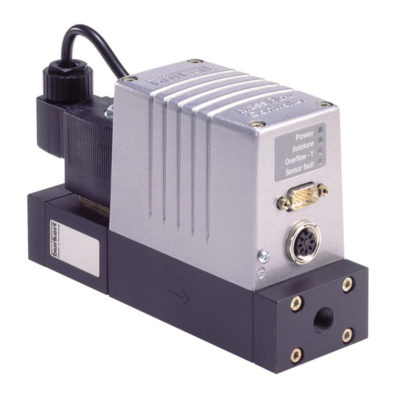
    Raccordements électriques La liaison électrique du MFC type 8626 avec l’alimentation en tension, la commande, etc. se fait par deux lignes, qui sont branchées à l’électronique par un connecteur rond à 7 pôles et un connecteur à fiche Sub-D à 9 pôles sur la face frontale du boîtier du MFC.
  • Page 57 On peut ainsi par ex. établir un diagnostic rapide à distance en cas d’apparition de problème. Vous obtiendrez de plus amples informations sur cette possibilité de service à l’adresse nommée en 1.3. Type 8626...
  • Page 58: Diodes Lumineuses D'affichage De L'état De Fonctionnement

    Diodes lumineuses d’affichage de l’état de fonctionnement „Power“ La diode verte est toujours allumée quand l’appareil est alimenté par la tension de service. „Autotune“ La lampe de contrôle rouge clignote si l’appareil traite la routine dite Autotune. Dans la routine, le domaine de valeur de réglage est adapté...
  • Page 59: Composants

    Un fois le calibrage effectué, on peut ainsi déduire du signal de capteur le débit total dans le canal d’écoulement. Dans le type MFC 8626, la mesure a lieu dans le flux principal , de telle sorte qu’un bonne dynamique est assurée.
  • Page 60: Régulateur

    2.5.2 Régulateur Le traitement des débits actuels de consigne et réel et le pilotage de l’organe de réglage est assuré par une électronique à microprocesseur. Le signal de tension analogique du capteur est filtré par l’électronique de réglage, numérisé et converti à l’aide d’une courbe de calibrage logée dans une EEPROM en une valeur numérique proportionnelle au débit réel.
  • Page 61: Vanne Proportionnelle

    è Tenez compte pour le choix de la vanne proportionnelle des caractéristiques fluidiques fondamentales de l’installation dans laquelle le MFC type 8626 est employé (v. 3.1). C’est ainsi seulement que les caractéristiques de débit voulues et les propriétés optimales de réglage seront assurées.
  • Page 62: Fonctionnement

    FONCTIONNEMENT Critères de sélection Les points suivants sont d’une importance décisive pour le choix du MFC: • l’exigence de la compatibilité des parties en contact avec le fluide avec les caractéristiques du gaz à régler; • la sélection correcte du coefficient de débit qui est défini essentiellement par la grandeur nominale de l’organe de réglage;...
  • Page 63 [kg/m³] sous les conditions normales (1013 mbar, 273 K) température du gaz en K : pressions absolues en [bar] avant et après le MFC type 8626 b) Si au contraire les pressions p et p à...
  • Page 64 L’autorité de la vanne ψ ne devrait pas se trouver au-dessous de 0,3 ... 0,5 dans l’intérêt d’une caractéristique de fonctionnement acceptable. Si ψ ψ ψ ψ ψ est inférieure à cette valeur indicative, le MFC type 8626, respectivement son organe de réglage, est surdimensionné, de telle sorte qu’à pleine ouverture sa résistance d’écoulement est nettement plus faible que celle des autres composants...
  • Page 65: Calibrage

    Calibrage Chaque MFC type 8626 est calibré au cours du contrôle final. Les données de calibrage obtenues sont déposées dans l’EEPROM du régulateur. Le calibrage est effectué normalement avec le gaz d‘ exploitation. Des exceptions forment des appareils pour les gaz azote, l’oxygène, ammoniaque ainsi que certains mélanges de gaz.
  • Page 66: Etats De Fonctionnement

    Autotune, afin d’assurer la fonction d’étanchéité de l’appareil. La sensibilité de réponse du MFC type 8626 lors de variations de la valeur de consigne est déterminée par la sensibilité de réponse de la vanne ainsi que par la résolution du convertisseur A/D.
  • Page 67: Mode Autotune

    Après un saut de valeur de consigne, le MFC type 8626 atteint en 500 ms max. la bande de ± 5% autour de la nouvelle valeur de consigne et reste dans cette bande.
  • Page 68: La Valeur De Consigne Ne Peut Pas Être Atteinte

    à 100% et que le débit ainsi obtenu ne suffit pas. La cause est en général une trop faible différence de pression sur le MFC type 8626, par ex. à la suite de l’effondrement de la pression d’alimentation ou de filtre fortement encrassé.
  • Page 69: Défaut De Capteur

    à 7 pôles) est activée. Compatibilité électromagnétique Le MFC type 8626 a un certificat de conformité de la CE pour des applications de ménage et d’industrie et a passé les contrôles CEM selon EN 50081-2:03/94 "Fach- grundnorm Störaussendung;Teil 2: Industriebereich" et EN 50082-2:02/96 "Fach- grundnorm Störfestigkeit;...
  • Page 70: Entretien

    Entretien Les MFC type 8626 sont en principe exempt d’entretien pour une exploitation correspondant aux indications données dans ces instructions de service. Si des quantités substantielles de particules de saleté sont devenues déposées sur le premier treillis métallique en acier inoxydable, vous pouvez le nettoyer ou substituer après avoir retiré...
  • Page 71: Derangements / Depannage

    La fluide de calibrage et la Renvoyez l'appareil au fabricant fluide de service diffèrent pour recalibrage corresponant notablement aux propriétées a la fluide de service actuelle thermales Type 8626...
  • Page 72: Accessoires

    ACCESSOIRES Numéro Article d'article Connecteur rond á 7-pôles Fa. Tuchel 646138 Connecteur á fiche Sub-D á 9-pôles IP65 917623 Connecteur rond á 7-pôles Fa. Tuchel, 784725 avec 3 m cable, fabriqué unilatéralement Connecteur á fiche Sub-D á 9-pôles IP65, 784726 avec 3 m cable, fabriqué...
  • Page 73 NOTES Type 8626...
  • Page 74 Berlin: Tel. (0 30) 67 97 17-0 Dresden: Tel. (03 59 52) 36 30-0 Frankfurt: Tel. (0 61 03) 94 14-0 Steuer- und Regeltechnik Hannover: Tel. (05 11 ) 9 02 76-0 Christian-Bürkert-Str. 13-17 Dortmund: Tel. (0 23 73) 96 81-0 74653 Ingelfingen München: Tel.

Table des Matières