Télécharger Imprimer la page

Publicité

Les langues disponibles

Les langues disponibles

Liens rapides

Before attempting to connect, operate or adjust this product, please read
these instructions completely.
Printed in Japan
VQT9557-2
Multi-Function Controller
Model AW-
P
P
F1101W2052 @

Publicité

loading

Sommaire des Matières pour Panasonic AW-RP605P

  • Page 1 Multi-Function Controller Model AW- Before attempting to connect, operate or adjust this product, please read these instructions completely. Printed in Japan F1101W2052 @ VQT9557-2...
  • Page 2 FCC Note: CAUTION This device complies with Part 15 of the FCC Rules. RISK OF ELECTRIC SHOCK To assure continued compliance follow the attached DO NOT OPEN installation instructions and do not make any unauthorized modifications. CAUTION: TO REDUCE THE RISK OF ELECTRIC SHOCK, DO NOT REMOVE COVER (OR BACK).
  • Page 3 Contents Introduction ........3 White balance adjustment ..... . .29 Accessories .
  • Page 4 Parts and their functions $ Control panel 7 8 9 CAMERA CONTROL PAN/TILT SET IRIS ZOOM FOCUS OPERATE OPEN TELE WHITE GAIN LAMP OPTION CONTRAST AUTO MANU MODE TRACING MEMORY START POINT START/STOP RESTORE RESET CAMERA DATA SET GAIN/PED MENU CONTROL INCOM TALLY...
  • Page 5 Parts and their functions $ Control panel < > CAMERA CONTROL PAN/TILT SET OPERATE IRIS ZOOM FOCUS OPEN TELE WHITE LAMP OPTION GAIN CONTRAST AUTO MANU MODE TRACING MEMORY START POINT START/STOP RESTORE RESET CAMERA DATA SET GAIN/PED MENU CONTROL INCOM TALLY TRACING/PRESET MEMORY...
  • Page 6 Parts and their functions $ Control panel CAMERA CONTROL PAN/TILT SET OPERATE IRIS ZOOM FOCUS OPEN TELE WHITE LAMP OPTION GAIN CONTRAST AUTO MANU MODE TRACING MEMORY START POINT START/STOP RESTORE RESET CAMERA DATA SET GAIN/PED MENU CONTROL INCOM TALLY TRACING/PRESET MEMORY CALL TR/PSET M.LOCK...
  • Page 7 Parts and their functions $ Control panel I J K L M N O CAMERA CONTROL PAN/TILT SET IRIS ZOOM FOCUS OPERATE OPEN TELE WHITE GAIN LAMP OPTION CONTRAST AUTO MANU MODE TRACING MEMORY START POINT START/STOP RESTORE RESET CAMERA DATA SET GAIN/PED MENU...
  • Page 8 Parts and their functions $ Control panel CAMERA CONTROL PAN/TILT SET OPERATE IRIS ZOOM FOCUS OPEN TELE WHITE LAMP OPTION GAIN CONTRAST AUTO MANU MODE TRACING MEMORY START POINT START/STOP RESTORE RESET CAMERA DATA SET GAIN/PED MENU CONTROL INCOM TALLY TRACING/PRESET MEMORY CALL TR/PSET M.LOCK...
  • Page 9 Parts and their functions $ Control panel CAMERA CONTROL PAN/TILT SET OPERATE IRIS ZOOM FOCUS OPEN TELE WHITE GAIN LAMP OPTION CONTRAST AUTO MANU MODE TRACING MEMORY START START/STOP RESTORE RESET POINT CAMERA MENU DATA SET GAIN/PED CONTROL INCOM TALLY TRACING/PRESET MEMORY CALL TR/PSET M.LOCK...
  • Page 10 Parts and their functions $ Control panel CAMERA CONTROL PAN/TILT SET OPERATE IRIS ZOOM FOCUS OPEN TELE WHITE LAMP OPTION GAIN CONTRAST AUTO MANU MODE TRACING MEMORY START POINT START/STOP RESTORE RESET CAMERA DATA SET GAIN/PED MENU CONTROL INCOM TALLY TRACING/PRESET MEMORY CALL TR/PSET M.LOCK...
  • Page 11 Parts and their functions $ Control panel b DC 12V IN socket d TERMINATION switch The power from the main unit is supplied to this socket. This is the control signal termination switch. The socket is connected to the CONTROL PANEL <Notes>...
  • Page 12 Parts and their functions $ Main unit TO PAN/TILT HEAD PO W ER VIDEO DC POWER OPTION CARD 75Ω AUTO VIDEO EXT/ SERVICE 75Ω PREVIEW DC 12V IN MONITOR OUT 1 PUSH REMOTE PREVIEW MONITOR OUT 2 PREVIEW MONITOR OUT 3 CONTROL PANEL POWER OUT TERMINATION...
  • Page 13 Parts and their functions $ Main unit < TO PAN/TILT HEAD VIDEO DC POWER OPTION CARD 75Ω AUTO VIDEO EXT/ SERVICE 75Ω PREVIEW DC 12V IN MONITOR OUT 1 PUSH REMOTE PREVIEW MONITOR OUT 2 PREVIEW MONITOR OUT 3 CONTROL PANEL POWER OUT TERMINATION TALK...
  • Page 14 Parts and their functions $ Main unit TO PAN/TILT HEAD VIDEO DC POWER OPTION CARD 75Ω AUTO VIDEO EXT/ SERVICE 75Ω PREVIEW DC 12V IN MONITOR OUT 1 PUSH REMOTE PREVIEW MONITOR OUT 2 PREVIEW MONITOR OUT 3 CONTROL PANEL POWER OUT TERMINATION TALK...
  • Page 15 Parts and their functions $ Main unit TO PAN/TILT HEAD VIDEO DC POWER OPTION CARD 75Ω AUTO VIDEO EXT/ SERVICE 75Ω PREVIEW DC 12V IN MONITOR OUT 1 PUSH REMOTE PREVIEW MONITOR OUT 2 PREVIEW MONITOR OUT 3 CONTROL PANEL POWER OUT TERMINATION TALK...
  • Page 16 Connections When using composite signals Turn off the power of all components before O The AW-CA50T29 (optional accessory) is required to proceeding with the connections. connect the convertible camera to the AW-PH350 pan-tilt head. O Use the AW-PS505 (optional accessory) for the main unit’s AC adapter and the AW-PS300 (optional O To connect the main unit and pan-tilt heads, use two accessory) for the pan-tilt head’s AC adapter.
  • Page 17 Connections When component signals are to be used as the video signals, the AW-PB302 RGB card (optional accessory) must be installed in the convertible camera. Convertible camera Iris control Zoom lens Zoom/focus control Pan-tilt head: AW-PH350 Pan-tilt head cable: AW-CA50T29 (for composite signal) AW-CA50C29 (for component signals)
  • Page 18 Connections When using a pan-tilt head other than the AW-PH350 When the AW-PH300, AW-PH300A, AW-PH500 or AW- PH600 is to be used as a pan-tilt head, the level of the control signals from the main unit must be converted from RS-422 to RS-232C.
  • Page 19 Connections Example of system configuration Halogen lamp Pan-tilt head system AC adapter: AW-PS300 VIDEO/Y G/L signal Video board: AW-PB605 Pan-tilt head system control signal Genlock signal generator Switcher, special effects generator, VIDEO/Y etc. AC adapter: AW-PS505 FUSE Preview color monitor (75 Ω...
  • Page 20 Operation $ Turning on the power $ Setting the travel range (limiters) of the pan-tilt head 1. Set all the power switches of the connected components and the power switch of the AC adapter to ON. Depending on where it has been installed, there may be obstacles within the travel range of the pan-tilt head system 2.
  • Page 21 Operation 4. Set the left-most limit position in the travel range. $ Setting the video signals 1 Operate the PAN/TILT lever on the control panel to rotate the camera to the position which is to serve as In the multi-function controller, the video signals (composite the left-most limit position.
  • Page 22 Operation $ Video signal cable compensation Signal deterioration caused by the length of the cables from If the automatic adjustment was not performed properly, the pan-tilt head to the main unit is compensated for. the following item appears on the LCD panel. When the length of the cables from the pan-tilt head to the main unit exceeds 500 meters, set the cable compensation C C A A B B L L E E C C O O M M P P A A U U T T O O...
  • Page 23 Operation Adjusting the cable compensation manually 7. Adjust the luminance signal using the menu setting When composite signals are used control (L) and the chrominance signal using the menu 1. Select pan-tilt head system using setting control (R). CONTROL/PREVIEW MONITOR OUT SEL button. Adjust the luminance and chrominance signals several times to the signal waveforms shown below.
  • Page 24 Operation When component signals are used 9. Turn the menu setting control (main), and set it so that the following item appears on the LCD panel. 1. Select pan-tilt head system using C C A A B B L L E E C C O O M M P P M M A A N N U U A A L L CONTROL/PREVIEW MONITOR OUT SEL button.
  • Page 25 Operation $ Genlock adjustment If a camera is to be synchronized with an external signal for use, genlock adjustment must be performed for the camera and other equipments. Either the black burst or VBS (video, burst and sync) signal is used for the external sync signal. There is no need to perform the genlock adjustment if the camera is not going to be synchronized with an external signal.
  • Page 26 Operation Horizontal phase adjustment 3•5 4 1. Select pan-tilt head system using CONTROL/PREVIEW MONITOR OUT SEL button. CAMERA CONTROL PAN/TILT SET OPERATE IRIS ZOOM FOCUS OPEN TELE WHITE GAIN LAMP OPTION AUTO CONTRAST 2. Supply the genlock signal to the G/L IN connector on the MANU MODE TRACING MEMORY...
  • Page 27 Operation Subcarrier phase adjustment 9. Select the next pan-tilt head system using the The subcarrier phase adjustment must be performed, when CONTROL/PREVIEW MONITOR OUT SEL button, and composite signals have been set as the video input signals continue adjusting the subcarrier phase in each system and the pictures are to be switched by a video switcher or concerned.
  • Page 28 Operation $ Total pedestal adjustment When more than one camera is to be used, the black level (pedestal level) of the pictures shot by each of the cameras must be brought into alignment. CAMERA CONTROL PAN/TILT SET OPERATE IRIS ZOOM FOCUS OPEN TELE...
  • Page 29 Operation $ White balance adjustment The white balance must be adjusted when the equipment is used for the first time, when it has not been used for a Manual adjustment of white balance prolonged time or when the lighting conditions or brightness 1.
  • Page 30 Operation $ Black balance adjustment The black balance must be adjusted when the equipment is Manual adjustment of black balance used for the first time, when it has not been used for a prolonged time, when the ambient temperature has changed 1.
  • Page 31 Operation $ Tracing memory settings The multi-function controller is equipped with a tracing 6. Select the next pan-tilt head system using the memory function for entering the series of settings with CONTROL/PREVIEW MONITOR OUT SEL button, and which pan-tilt head systems is operated. continue setting the entry times and number of The tracing memories are entered into TRACING/PRESET memories for each system concerned.
  • Page 32 Operation Entering the tracing memory data 8. The entry in the tracing memory commences as soon as 1. Select pan-tilt head system using the pan, tilt, zoom, focus, iris or white balance mode CONTROL/PREVIEW MONITOR OUT SEL button. selection is initiated so proceed with the entry operation. The START/STOP button stops flashing and comes on, 2.
  • Page 33 Operation Recalling tracing memory data Making changes to the tracing memory 1. Select pan-tilt head system using 1. Select pan-tilt head system using CONTROL/PREVIEW MONITOR OUT SEL button. CONTROL/PREVIEW MONITOR OUT SEL button. 2. Press the button in which the tracing memory data to be 2.
  • Page 34 Operation Deleting tracing memory data 1. Select pan-tilt head system using CONTROL/PREVIEW MONITOR OUT SEL button. 2. While holding down the RESET button, press the buttons in which the tracing memory data to be deleted has been entered. <Note> The lamps of the buttons in which tracing memory data has been entered (TRACING/PRESET MEMORY buttons 1 through 10) come on when the RESET button is pressed.
  • Page 35 Operation $ Preset memory settings The multi-function controller is equipped with a preset memory function for entering the positions and settings with which the pan-tilt head system is to shoot. Preset memory data is entered into TRACING/PRESET CAMERA CONTROL PAN/TILT SET OPERATE IRIS ZOOM...
  • Page 36 Setting menus G/L SETTING CABLE LENGTH [SHORT] H PHASE [± 0] [COARSE: 1, FINE: ± 0] SC PHASE With the COARSE setting, it is not possible to switch the speed at which the setting value changes when the jog dial is pressed. CABLE COMP CABLE COMP AUTO CABLE COMP MANUAL (Y, C)
  • Page 37 Setting menus CAMERA SETTING SCENE [USER] USER HALOGEN SHUTTER [OFF] SHUTTER [OFF] DETAIL [HIGH] DETAIL [HIGH] PICTURE LEVEL [± 0] [PAL AUTO IRIS LEVEL] PICTURE LEVEL [± 0] [PAL AUTO IRIS LEVEL] LIGHT PEAK/AVG [PAL AUTO IRIS PEAK/AVG] LIGHT PEAK/AVG [PAL AUTO IRIS PEAK/AVG] LIGHT AREA [TOP CUT]...
  • Page 38 Setting menus G/L SETTING (genlock adjustment) CONTROLLER SETTING (controller menu setting) menu CABLE LENGTH (SHORT, LONG) SIGNAL SELECT This item sets the compensation for the length of the BNC (C.VIDEO5C.VIDEO, Y/Pr/Pb5C.VIDEO, Y/Pr/Pb5Y/Pr/Pb) cable used for the genlock signals. “SHORT” is set when This is used to set the multi-function controller’s input the cable is less than 500 meters long;...
  • Page 39 Setting menus P/T SETTING (pan-tilt head setting) menu IRIS DIRECTION (NORMAL/REVERSE) PAN DIRECTION (NORMAL/REVERSE) This item is used to select the focus operations of the lens This item is used to select the operations in the horizontal which are to be performed by operating the dials on the top direction of the pan-tilt head system which are to be of the PAN/TILT lever and ZOOM lever.
  • Page 40 Setting menus SPEED WITH ZOOM POS. (OFF, 1, 2) CAMERA SETTING menu When 1 or 2 is selected as this item’s setting, the pan-tilt operation of the pan-tilt head system is slowed down so that The operation items differ depending on the type of camera the pan-tilt position will be more easily aligned when the or pan-tilt head used and the optional card installed.
  • Page 41 Installing additional video boards The multi-function controller comes with four slots for installing additional video boards. By adding the AW-PB605 video boards (optional accessory), up to five pan-tilt head systems can be controlled. Before installing additional video boards, set the power switches of the components to the OFF position, and disconnect the power cords from the power outlets.
  • Page 42 Attaching the rack mounting adapters To install the main unit in a rack, use the rack mounting adapters and mounting screws (M4a8 mm) supplied. Replacement of consumable parts O Battery replacement O Joystick replacement The battery has a life of 5 years. Replace the battery The joystick is a consumable part.
  • Page 43 Specifications [GENERAL] [MAIN UNIT] $ Input connectors Power supply: DC 10.8 V to DC 16 V DC 12V IN socket Power consumption: 14.0 W XLR, 4 pins CONTROL IN TO CONTROL PANEL [1, 2, 3] connectors indicates safety information. RJ45 a3 Connecting cable: Ambient operating temperature 10BaseT straight cables (UTP category 5),...
  • Page 44 Specifications [VIDEO BOARD] $ Input connectors VIDEO/Y IN, Pr IN, Pb IN BNC a3, 75Ω termination, 7.5% setup Composite: = 100 IRE Sync = 40 IRE Burst = 40 IRE Component: = 0.714 V Sync = 0.286 V Pr/Pb = 0.700 V $ Output connectors G/L OUT connector BNC, 75Ω...
  • Page 46 PANASONIC BROADCAST & TELEVISION SYSTEMS COMPANY UNIT COMPANY OF MATSUSHITA ELECTRIC CORPORATION OF AMERICA Executive Office: One Panasonic Way 4E-7, Secaucus, NJ 07094 (201) 348-7000 EASTERN ZONE: One Panasonic Way 4E-7, Secaucus, NJ 07094 (201) 348-7621 Southeast Region: 1225 Northbrook Parkway, Ste 1-160, Suwanee, GA 30024 (770) 338-6835...
  • Page 47 Coordonnateur multi-fonctions Modèle AW- Avant de raccorder, de faire fonctionner ou de régler l’appareil, lire attentivement tout ce manuel.
  • Page 48 ATTENTION: ATTENTION AFIN PRÉVENIR TOUT RISQUE RISQUE DE CHOCS ÉLECTRIQUES D’INCENDIE, DE CHOCS ÉLECTRIQUES OU NE PAS OUVRIR D’INTERFÉRENCES, N’UTILISER QUE LES ATTENTION: AFIN DE PRÉVENIR LE RISQUE DE CHOCS ACCESSOIRES RECOMMANDÉS. ÉLECTRIQUES, NE PAS RETIRER LES VIS. TOUTE RÉPARATION DEVRAIT ÊTRE CONFIÉE À UN PERSONNEL COMPÉTENT.
  • Page 49 Table des matières Introduction ........3 Réglage de l’équilibre des blancs .
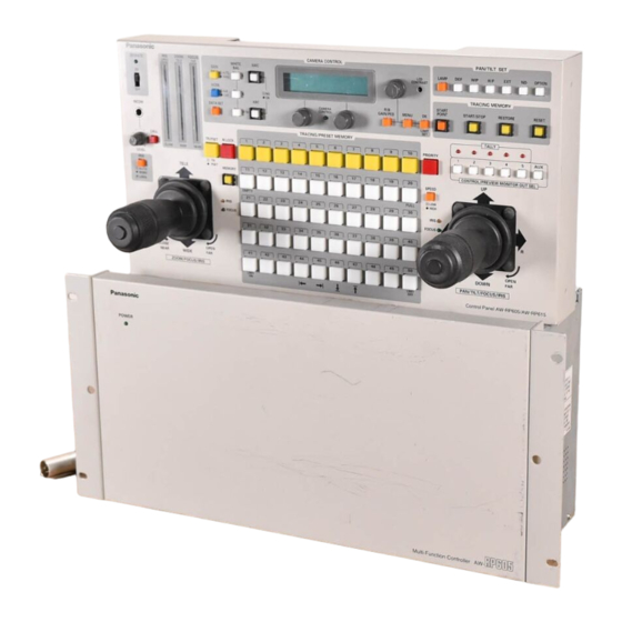
  • Page 50 Les commandes et leurs fonctions $ Panneau de commande 7 8 9 CAMERA CONTROL PAN/TILT SET IRIS ZOOM FOCUS OPERATE OPEN TELE WHITE GAIN LAMP OPTION CONTRAST AUTO MANU MODE TRACING MEMORY START POINT START/STOP RESTORE RESET CAMERA DATA SET GAIN/PED MENU CONTROL...
  • Page 51 Les commandes et leurs fonctions $ Panneau de commande < > CAMERA CONTROL PAN/TILT SET OPERATE IRIS ZOOM FOCUS OPEN TELE WHITE LAMP OPTION GAIN CONTRAST AUTO MANU MODE TRACING MEMORY START POINT START/STOP RESTORE RESET CAMERA DATA SET GAIN/PED MENU CONTROL INCOM...
  • Page 52 Les commandes et leurs fonctions $ Panneau de commande CAMERA CONTROL PAN/TILT SET OPERATE IRIS ZOOM FOCUS OPEN TELE WHITE LAMP OPTION GAIN CONTRAST AUTO MANU MODE TRACING MEMORY START POINT START/STOP RESTORE RESET CAMERA DATA SET GAIN/PED MENU CONTROL INCOM TALLY TRACING/PRESET MEMORY...
  • Page 53 Les commandes et leurs fonctions $ Panneau de commande I J K L M N O CAMERA CONTROL PAN/TILT SET IRIS ZOOM FOCUS OPERATE OPEN TELE WHITE GAIN LAMP OPTION CONTRAST AUTO MANU MODE TRACING MEMORY START POINT START/STOP RESTORE RESET CAMERA DATA SET...
  • Page 54 Les commandes et leurs fonctions $ Panneau de commande CAMERA CONTROL PAN/TILT SET OPERATE IRIS ZOOM FOCUS OPEN TELE WHITE LAMP OPTION GAIN CONTRAST AUTO MANU MODE TRACING MEMORY START POINT START/STOP RESTORE RESET CAMERA DATA SET GAIN/PED MENU CONTROL INCOM TALLY TRACING/PRESET MEMORY...
  • Page 55 Les commandes et leurs fonctions $ Panneau de commande CAMERA CONTROL PAN/TILT SET OPERATE IRIS ZOOM FOCUS OPEN TELE WHITE GAIN LAMP OPTION CONTRAST AUTO MANU MODE TRACING MEMORY START START/STOP RESTORE RESET POINT CAMERA MENU DATA SET GAIN/PED CONTROL INCOM TALLY TRACING/PRESET MEMORY...
  • Page 56 Les commandes et leurs fonctions $ Panneau de commande CAMERA CONTROL PAN/TILT SET OPERATE IRIS ZOOM FOCUS OPEN TELE WHITE LAMP OPTION GAIN CONTRAST AUTO MANU MODE TRACING MEMORY START POINT START/STOP RESTORE RESET CAMERA DATA SET GAIN/PED MENU CONTROL INCOM TALLY TRACING/PRESET MEMORY...
  • Page 57 Les commandes et leurs fonctions $ Panneau de commande b Prise DC 12V IN (entrée c.c. 12 V) d Commutateur TERMINATION (terminaison) L’alimentation envoyée par l’appareil principal arrive à cette C’est le commutateur de terminaison du signal de prise. La prise se raccorde à la prise CONTROL PANEL commande.
  • Page 58 Les commandes et leurs fonctions $ Appareil principal TO PAN/TILT HEAD PO W ER VIDEO DC POWER OPTION CARD 75Ω AUTO VIDEO EXT/ SERVICE 75Ω PREVIEW DC 12V IN MONITOR OUT 1 PUSH REMOTE PREVIEW MONITOR OUT 2 PREVIEW MONITOR OUT 3 CONTROL PANEL POWER OUT...
  • Page 59 Les commandes et leurs fonctions $ Appareil principal < TO PAN/TILT HEAD VIDEO DC POWER OPTION CARD 75Ω AUTO VIDEO EXT/ SERVICE 75Ω PREVIEW DC 12V IN MONITOR OUT 1 PUSH REMOTE PREVIEW MONITOR OUT 2 PREVIEW MONITOR OUT 3 CONTROL PANEL POWER OUT TERMINATION...
  • Page 60 Les commandes et leurs fonctions $ Appareil principal TO PAN/TILT HEAD VIDEO DC POWER OPTION CARD 75Ω AUTO VIDEO EXT/ SERVICE 75Ω PREVIEW DC 12V IN MONITOR OUT 1 PUSH REMOTE PREVIEW MONITOR OUT 2 PREVIEW MONITOR OUT 3 CONTROL PANEL POWER OUT TERMINATION TALK...
  • Page 61 Les commandes et leurs fonctions $ Appareil principal TO PAN/TILT HEAD VIDEO DC POWER OPTION CARD 75Ω AUTO VIDEO EXT/ SERVICE 75Ω PREVIEW DC 12V IN MONITOR OUT 1 PUSH REMOTE PREVIEW MONITOR OUT 2 PREVIEW MONITOR OUT 3 CONTROL PANEL POWER OUT TERMINATION TALK...
  • Page 62 Raccordements Lors de l’utilisation de signaux Mettre tous les appareils hors contact avant de procéder composites aux raccordements. O Pour pouvoir raccorder la caméra convertible à la tête panoramique AW-PH350, il faudra se procurer le modèle O Utiliser modèle AW-PS505 (accessoire vendu AW-CA50T29 (accessoire vendu séparément).
  • Page 63 Raccordements Pour pouvoir utiliser des signaux à composantes comme signaux vidéo, il faudra installer la plaque RGB AW-PB302 (accessoire vendu séparément) dans la caméra convertible. Caméra convertible Commande de diaphragme Zoom Commande de zoom/mise au point Tête panoramique: AW-PH350 Câble de tête panoramique: AW-CA50T29 (pour les signaux composites) AW-CA50C29 (pour les...
  • Page 64 Raccordements Lors de l’utilisation d’une tête panoramique autre que le modèle AW- PH350 Lorsque la tête panoramique utilisée est le modèle AW-PH300, AW-PH300A, AW-PH500 ou AW-PH600, il faudra convertir le niveau des signaux de commande envoyés par l’appareil principal de RS-422 à RS-232C. Pour le convertisseur RS-232C/RS-422 et le câble de raccordement, consulter son détaillant.
  • Page 65 Raccordements Exemple de configuration système Lampe halogène Système de tête panoramique Bloc d’alimentation: AW-PS300 VIDEO/Y Signal G/L Plaque vidéo: AW-PB605 Signal de commande de système de tête panoramique Générateur de signal de générateur asservi Bloc de commutation, générateur d’effets spéciaux, etc. VIDEO/Y Bloc d’alimentation: AW-PS505...
  • Page 66 Fonctionnement $ Etablissement du contact $ Réglage de la plage de déplacement (limiteurs) de la tête panoramique 1. Placer tous les interrupteurs des appareils raccordés et l’interrupteur du bloc d’alimentation à la position ON. Selon le lieu où le système de tête panoramique a été installé, il est possible qu’il y ait des obstacles dans la plage de 2.
  • Page 67 Fonctionnement 4. Régler la limite extrême gauche de la plage de $ Réglage des signaux vidéo déplacement. 1 Actionner le levier PAN/TILT du panneau de commande Dans le coordonnateur multi-fonctions, il faut régler les signaux pour faire pivoter la caméra sur la position qui doit servir vidéo (signaux composites et signaux à...
  • Page 68 Fonctionnement $ Compensation du câble de signal vidéo Il est possible de compenser la détérioration du signal Si le réglage automatique ne s’est pas effectué correctement, provoquée par la longueur des câbles entre la tête la rubrique suivante s’affiche sur le panneau LCD. panoramique et l’appareil principal.
  • Page 69 Fonctionnement Réglage manuel de la compensation du câble 7. Régler le signal luminance avec la commande réglage du Lors de l’utilisation de signaux composites menu (L) et le signal chrominance avec la commande 1. Sélectionner le système de tête panoramique avec la réglage du menu (R).
  • Page 70 Fonctionnement Lors de l’utilisation de signaux à composantes 9. Tourner la commande réglage du menu (principale), et la régler de manière que la rubrique suivante apparaisse sur le 1. Sélectionner le système de tête panoramique avec la panneau LCD. touche CONTROL/PREVIEW MONITOR OUT SEL. C C A A B B L L E E C C O O M M P P M M A A N N U U A A L L f f R R e e s s p p o o n n s s e e : : 2.
  • Page 71 Fonctionnement $ Réglage du générateur asservi Si la caméra doit être synchronisée sur un signal externe, il faudra régler le générateur asservi de la caméra et des autres appareils. Le signal de salve noire ou le signal VBS (vidéo, salve et synchronisation) peuvent être utilisés comme signal de synchronisation externe.
  • Page 72 Fonctionnement Réglage de la phase horizontale 3•5 4 1. Sélectionner le système de tête panoramique avec la touche CONTROL/PREVIEW MONITOR OUT SEL. CAMERA CONTROL PAN/TILT SET OPERATE IRIS ZOOM FOCUS OPEN TELE WHITE GAIN LAMP OPTION 2. Envoyer le signal du générateur asservi au connecteur G/L AUTO CONTRAST MANU...
  • Page 73 Fonctionnement Réglage de la phase de la sous-porteuse 9. Sélectionner le système de tête panoramique suivant avec Le réglage de la phase de la sous-porteuse doit être effectué la touche CONTROL/PREVIEW MONITOR OUT SEL, et lorsque les signaux composites ont été réglés comme signaux continuer à...
  • Page 74 Fonctionnement $ Réglage de la suppression totale Si plusieurs caméras sont utilisées, le niveau de noir (niveau de suppression) des images prises par chacune des caméras doit être aligné. CAMERA CONTROL PAN/TILT SET OPERATE IRIS ZOOM FOCUS OPEN TELE WHITE GAIN LAMP OPTION...
  • Page 75 Fonctionnement $ Réglage de l’équilibre des blancs Il faudra régler l’équilibre des blancs lorsque l’appareil est utilisé Réglage manuel de l’équilibre des blancs pour la première fois, s’il n’a pas servi pendant longtemps, ou si les conditions de luminosité ont changé. 1.
  • Page 76 Fonctionnement $ Réglage de l’équilibre des noirs Il faudra régler l’équilibre des noirs lorsque l’appareil est utilisé Réglage manuel de l’équilibre des noirs pour la première fois, s’il n’a pas servi pendant longtemps, si la température ambiante a considérablement changé et aux 1.
  • Page 77 Fonctionnement $ Réglage de la mémoire tracé Le coordonnateur multi-fonctions est équipé d’une mémoire 6. Sélectionner le système de tête panoramique suivant avec tracé qui s’utilise pour entrer les séries de réglages auxquels la touche CONTROL/PREVIEW MONITOR OUT SEL, et les systèmes de tête panoramique fonctionnent.
  • Page 78 Fonctionnement Entrée des données dans la mémoire tracé 8. L’entrée dans la mémoire tracé débute dès que la sélection 1. Sélectionner le système de tête panoramique avec la du mode déplacement horizontal, déplacement vertical, touche CONTROL/PREVIEW MONITOR OUT SEL. mise au point, diaphragme ou équilibre des blancs est effectuée, donc procéder avec l’opération d’entrée.
  • Page 79 Fonctionnement Rappel des données de la mémoire tracé Modifications de la mémoire tracé 1. Sélectionner le système de tête panoramique avec la 1. Sélectionner le système de tête panoramique avec la touche CONTROL/PREVIEW MONITOR OUT SEL. touche CONTROL/PREVIEW MONITOR OUT SEL. 2.
  • Page 80 Fonctionnement Suppression des données de la mémoire tracé 1. Sélectionner le système de tête panoramique avec la touche CONTROL/PREVIEW MONITOR OUT SEL. 2. Tout en maintenant la pression sur la touche RESET, appuyer sur les touches sur lesquelles les données de mémoire tracé...
  • Page 81 Fonctionnement $ Réglage de la mémoire préréglage Le coordonnateur multi-fonctions est équipé d’une mémoire préréglage qui s’utilise pour entrer les positions et les réglages auxquels le système de tête panoramique doit effectuer la prise de vues. CAMERA CONTROL PAN/TILT SET OPERATE IRIS ZOOM...
  • Page 82 Réglage des menus G/L SETTING CABLE LENGTH [SHORT] H PHASE [± 0] [COARSE: 1, FINE: ± 0] SC PHASE Avec le paramètre COARSE, il n’est pas possible de régler la vitesse à laquelle le paramètre change quand la commande de réglage est pressée. CABLE COMP CABLE COMP AUTO CABLE COMP MANUAL (Y, C)
  • Page 83 Réglage des menus CAMERA SETTING SCENE [USER] USER HALOGEN SHUTTER [OFF] SHUTTER [OFF] DETAIL [HIGH] DETAIL [HIGH] PICTURE LEVEL [± 0] [PAL AUTO IRIS LEVEL] PICTURE LEVEL [± 0] [PAL AUTO IRIS LEVEL] LIGHT PEAK/AVG [PAL AUTO IRIS PEAK/AVG] LIGHT PEAK/AVG [PAL AUTO IRIS PEAK/AVG] LIGHT AREA [TOP CUT]...
  • Page 84 Réglage des menus Menu G/L SETTING Menu CONTROLLER SETTING (réglage du générateur asservi) (réglage du coordonnateur) CABLE LENGTH (SHORT, LONG) SIGNAL SELECT Cette rubrique permet de régler la compensation de la longueur (C.VIDEO5C.VIDEO, Y/Pr/Pb5C.VIDEO, Y/Pr/Pb5Y/Pr/Pb) du câble BNC utilisé pour les signaux du générateur asservi. Cette rubrique permet de régler les signaux d’entrée et les Régler “SHORT”...
  • Page 85 Réglage des menus Menu P/T SETTING (réglage de la tête panoramique) IRIS DIRECTION (NORMAL/REVERSE) PAN DIRECTION (NORMAL/REVERSE) Cette rubrique permet de sélectionner les opérations de mise Cette rubrique permet de sélectionner les opérations de la au point de l’objectif qui doivent être effectuées avec les direction horizontale du système de tête panoramique qui commandes de réglage sur le dessus du levier PAN/TILT et du doivent être effectuées sur action du levier PAN/TILT.
  • Page 86 Réglage des menus DIAGONAL MOTION (ON/OFF) Menu CAMERA SETTING OFF : Le système de tête panoramique vient se placer à la position réglée dans la mémoire de préréglage à la Les rubriques de fonctionnent diffèrent selon le type de caméra vitesse maximale.
  • Page 87 Installation de plaques vidéo additionnelles Le coordonnateur multi-fonctions est équipé de quatre emplacements pour l’installation plaques vidéo additionnelles. En ajoutant les plaques vidéo AW-PB605 (accessoires vendus séparément), il sera possible de piloter un maximum de cinq systèmes de tête panoramique. Avant d’installer les plaques vidéo additionnelles, placer les interrupteurs des appareils à...
  • Page 88 Fixation des adaptateurs de montage en baie Pour installer l’appareil dans une baie, utiliser les adaptateurs de montage en baie et les vis de montage (M4a8 mm) fournis. Remplacement des pièces consommables O Remplacement de la pile O Remplacement de la manette La pile a une autonomie de 5 ans.
  • Page 89 Données techniques [DONNÉES GÉNÉRALES] [APPAREIL PRINCIPAL] $ Connecteurs d’entrée Alimentation: +10,8 V c.c. à 16 V c.c. Prise DC 12V IN Consommation: 14,0 W XLR, 4 contacts Connecteurs CONTROL IN TO CONTROL PANEL [1, 2, 3] indique les consignes de sécurité. RJ45 a3 Câble de raccordement: Température de fonctionnement ambiante...
  • Page 90 Données techniques [PLAQUE VIDÉO] $ Connecteurs d’entrée VIDEO/Y IN, Pr IN, Pb IN BNC a3, terminaison 75Ω, établissement à 7,5% Composites: = 100 IRE Synchronisation = 40 IRE Salve = 40 IRE Composantes: = 0,714 V Synchronisation = 0,286 V Pr/Pb = 0,700 V $ Connecteurs de sortie...
  • Page 92 Panasonic Canada Inc. 5770 Ambler Drive, Mississauga, Ontario L4W 2T3 (905) 624-5010...
  • Page 93 This file has been downloaded from: www.UsersManualGuide.com User Manual and User Guide for many equipments like mobile phones, photo cameras, monther board, monitors, software, tv, dvd, and othes.. Manual users, user manuals, user guide manual, owners manual, instruction manual, manual owner, manual owner's, manual guide, manual operation, operating manual, user's manual, operating instructions, manual operators, manual operator, manual product, documentation manual, user maintenance, brochure, user reference, pdf manual...