Télécharger Imprimer la page
Kessel Aqualift S Basic Mono Tronic Instructions D'installation Et D'utilisation

Kessel Aqualift S Basic Mono Tronic Instructions D'installation Et D'utilisation

Publicité

Les langues disponibles
  • FR

Les langues disponibles

  • FRANÇAIS, page 38

Liens rapides

Einbau und Betriebsanleitung
DE
DE
........................................................................................................................ 2
........................................................................................................................ 2
EN
EN
...................................................................................................................... 20
...................................................................................................................... 20
FR
FR
...................................................................................................................... 38
...................................................................................................................... 38
IT
IT
...................................................................................................................... 56
...................................................................................................................... 56
NL
NL
...................................................................................................................... 74
...................................................................................................................... 74
PL
PL
...................................................................................................................... 92
...................................................................................................................... 92
2020-11
Aqualift S Basic
Aqualift S Basic
Mono/Duo Tronic
Mono/Duo Tronic
016-233_01

Publicité

loading

Sommaire des Matières pour Kessel Aqualift S Basic Mono Tronic

  • Page 1 Aqualift S Basic Aqualift S Basic Mono/Duo Tronic Mono/Duo Tronic Einbau und Betriebsanleitung Einbau und Betriebsanleitung ........................2 ........................2 ........................20 ........................20 ........................38 ........................38 ........................56 ........................56 ........................74 ........................74 ........................92 ........................92 2020-11 016-233_01...
  • Page 2 Liebe Kundin, lieber Kunde, als Premiumhersteller von innovativen Produkten für die Entwässerungstechnik bietet KESSEL ganzheitliche Systemlösun- gen und kundenorientierten Service. Dabei stellen wir höchste Qualitätsstandards und setzen konsequent auf Nachhaltig- keit - nicht nur bei der Herstellung unserer Produkte, sondern auch im Hinblick auf deren langfristigen Betrieb setzen wir uns dafür ein, dass Sie und Ihr Eigentum dauerhaft geschützt sind.
  • Page 3 Hinweise zu dieser Anleitung Folgende Darstellungskonventionen erleichtern die Orientierung: Darstellung Erläuterung siehe Abbildung 1 Positionsnummer 5 von nebenstehender Abbildung Handlungsschritt in Abbildung Prüfen, ob Handbetrieb aktiviert wurde. Handlungsvoraussetzung OK betätigen. Handlungsschritt Anlage ist betriebsbereit. Handlungsergebnis Querverweis auf Kapitel 2 siehe "Sicherheit", Seite 4 Fettdruck besonders wichtige oder sicherheitsrelevante Information Variante oder Zusatzinformation (z.
  • Page 4 Sicherheit Allgemeine Sicherheitshinweise Bei Installation, Betrieb, Wartung oder Reparatur der Anlage sind die Unfallverhütungsvorschriften, die in Frage kommenden Normen und Richtlinien, sowie die Vorschriften der örtlichen Energie- und Versorgungsunternehmen zu beachten. ACHTUNG Anlage freischalten! Sicherstellen, dass die elektrischen Komponenten während der Arbeiten von der Spannungsversorgung getrennt sind.
  • Page 5 Der Betreiber der Anlage ist dazu verpflichtet: eine Gefährdungsbeurteilung zu erstellen, entsprechende Gefährdungszonen zu ermitteln und auszuweisen, Sicherheitsunterweisungen durchzuführen, gegen die Benutzung durch Unbefugte zu sichern. Person freigegebene Tätigkeiten an KESSEL-Anlagen Betreiber Sichtprüfung, Batterietausch Sachkundiger (kennt, ver- Entleerung, Reinigung steht Betriebsanweisung)
  • Page 6 Produktbeschreibung Die Anlage ist zum Einbau ins Erdreich, in den mitgelieferten Schacht, außerhalb von Gebäuden vorgesehen. Die Anlage wird für die Bestückung mit einer oder zwei Pumpen (Mono/ Duo) hergestellt. Der Aufbau der beiden Pumpen und deren Verrohrung ist symmetrisch. Ausführungen: Mono Tronic (mit Schaltgerät) Duo Tronic (mit Schaltgerät)
  • Page 7 Technische Daten Technische Daten der Pumpen Angabe / GTF 600 GTF 1250 Pumpenart Gewicht 6 kg 10 kg Leistung P1 / P2 650W / 400 W 1,3 kW / 0,8 kW Drehzahl 2750 min 2700 min Betriebsspannung 230 V; 50 Hz 230 V;...
  • Page 8 Montage Bodenaushub und Platzierung der Anlage Eignung von Produkt(-variante) für Umgebungsbedin- gungen (siehe "Bestimmungsgemäße Verwendung") und Einbautiefe (siehe "Produktbeschreibung") sicherstellen. Böschungswinkel β (ca. 60°) festlegen. Baugrube ausheben, dabei am Fuß mind. 50 cm umlau- fenden Untergrund sicherstellen. Baugrube mit einer Sauberkeitsschicht(1) von 30 cm ver- dichten und plan nivellieren.
  • Page 9 Kabeldurchführung herstellen Anschluss Kabelleerrohr (Variante A) Das Kabelleerrohr ist mit maximal 45°-Bögen auszu- führen. Bohrer mit passender Sägeglocke (Art.-Nr. 500101) aus- wählen. Bohrung für Kabelleerrohr gemäß der Anleitung der Sägeglocke ausführen. Dichtung für Rohrdurchführung einsetzen. Kabelleerrohr einfetten und durch Dichtung für Rohr- durchführung schieben.
  • Page 10 Schwimmerhalterung montieren (Tronic) Schwimmerhalterung einsetzen. Schwimmerhalterung mit Drehverschluss arretieren. Elektroanschlüsse am Schaltgerät vornehmen (siehe "Elektrischer Anschluss"). Abdeckplatte montieren Dichtung lagerichtig in Schacht einlegen, dann fetten. Abdeckplatte aufsetzen. 3 Schrauben festziehen, Korrosionsschutz auf Schrau- benköpfe aufsetzen. Dichtheitsprüfung Sicherstellen, dass die Anlage stromlos, sauber und frei von Bauschutt ist. Dem Behälter klares Wasser zuführen, bis die Oberkante des Behälters (nicht des Verlängerungsstückes) erreicht ist.
  • Page 11 Schaltgerät (Tronic) 4.9.1 Schaltgerät montieren Montageposition wählen, dabei Folgendes sicherstellen: Eine Schutzkontaktsteckdose befindet sich in unmittel- barer Nähe zum Schaltgerät. Die Anschlusskabel von Abwasserpumpe und Schwimmerschalter können fachgerecht installiert und bis zum Schaltgerät geführt werden. Das Schaltgerät kann sicher und ausreichend befestigt werden.
  • Page 12 Anschlussplan (Mono) (1) Netzanschluss (3) Schwimmerschalter (4) Alarm Braun Grün/ Gelb Grau Anschluss für Anschluss für Gelb externen Fern- externen Fern- Weiß Grün signalgeber/ signalgeber/ Blau Rosa Nicht potentialfreien potentialfreien belegt Kontakt (optio- Kontakt (optio- (2) Abwasserpumpe Braun nal nachrüstbar nal nachrüstbar Grün/ Braun...
  • Page 13 Potentialfreier Kontakt Es kann ein potentialfreier Kontakt als Erweiterungsset an das Schaltgerät angeschlossen werden, erhältlich als Zubehör (Art.-Nr. 80074). Mit diesem kann das Gerät mit der Gebäudeleittechnik oder weiteren Zubehörteilen wie z. B. der Warn- leuchte (Art.-Nr. 97715) verbunden werden. Stromversorgung herstellen zum Verwenden des potentialfreien Kontaktes gleichtzeitig Alarm-Taste (2) und Handbetriebtaste (4) für 10 Sekunden gedrückt halten.
  • Page 14 Inbetriebnahme Für die Inbetriebnahme ist die EN 12056-4 zu beachten. Prüfung der Anlage Vor Inbetriebnahme sind folgende Punkte zu prüfen: Korrekter Einbau der Pumpe(n) Fixierung aller entnehmbaren Bauteile Dichtheit der Anlage Netzspannung (max. Abweichung ± 10 %) Korrekter Sitz der Elemente zur Niveauerfassung Anlage ist sauber und frei von Bauschutt Inbetriebnahme der Anlage (Varianten Tronic mit Schaltgerät) Schaltgerät initialisieren...
  • Page 15 Betrieb Handbetrieb LED - Handbetrieb LED - Handbetrieb (nur bei Duo) Taste Pumpe 1 (10) Taste Pumpe 2 (nur bei Duo) Der Handbetrieb kann mit der Taste (9) / (10) aktiviert wer- den. Es findet dann kein automatisches Einschalten der Abwasserpumpe mehr statt.
  • Page 16 Betriebszustände Signalton Beschreibung Maßnahme grün orange orange (Intervall) (4) /(5) Außer Betrieb, keine Netzspannung Batterieüberwachung wiederherstellen Betriebsbereit Anlagenbehälter voll, es Keine Maßnahme not- wird in Kürze abgepumpt wendig, Abwasserpumpe kann mit Taste (8) aus- Anlagenbehälter geschaltet werden (siehe wird leergepumpt "Handbetrieb", Seite 15) Potentialfreier Kontakt wird aktiviert (Art.-Nr.
  • Page 17 Anlage ausschalten Netzstecker des Schaltgeräts ausstecken und warten, bis nach ein paar Sekunden der Alarm für den Netzaus- fall aktiviert wird (kurzer, wiederholter Signalton und die Alarm-LED (2) blinkt) Taster Alarm (7) drücken und so lange gedrückt halten, bis die Alarm-LED (2) nicht mehr blinkt, es ertönen vier kurze Signaltöne, das Schaltgerät ist ausgeschaltet Ist das Schaltgerät ausgeschaltet, ist der Batteriean- schluss deaktiviert.
  • Page 18 Einhandverschluss am Druckstutzen öffnen. Pumpe komplett mit Druckleitung am Griff herauszie- hen. VORSICHT Angestautes Abwasser läuft aus! Pumpenteile auf Verformung und Ablagerungen prüfen, ggf. KESSEL-Service kontaktieren. Leichtgängigkeit der beweglichen Teile sicherstellen. Sichtprüfung der Armaturenkomponenten durchführen. Schwimmerschalter feucht abwischen. Freistromrad reinigen/warten Spiralgehäuse demontieren.
  • Page 19 Niveauerfassung Drehverschluss öffnen. Alarmsonde (optional) und Schwimmerhalterung aus den Halterungen herausnehmen. Alle Teile zur Reinigung in Wasserbad eintauchen, danach feucht abwischen. Komponenten in umgekehrter Reihenfolge wieder zusam- menbauen. Rückflussverhinderer VORSICHT Angestautes Abwasser läuft aus! Drehverschluss öffnen. Rückschlagklappe herausnehmen. Rückschlagklappe reinigen. Komponenten auf Verschließ...
  • Page 20 Dear Customer, As a premium manufacturer of innovative products for draining technology, KESSEL offers integrated system solutions and customer-oriented service. In doing so, we set the highest quality standards and focus firmly on sustainability - not only with the manufacturing of our products, but also with regard to their long-term operation and we strive to ensure that you and your property are protected over the long term.
  • Page 21 Notes on this manual The following conventions make it easier to navigate the manual: Symbol Explanation See Figure 1 Position number 5 from the adjacent figure Action step in figure Check whether manual operation has been Prerequisite for action activated. Press OK.
  • Page 22 Safety General safety notes The accident prevention regulations, the applicable standards and directives as well as the regulations from the local energy and supply companies must be observed during the installation, operation, maintenance and repair of the system. NOTICE Disconnect system from energy sources! Ensure that the electrical components are disconnected from the electrical power supply during the work.
  • Page 23 Person Approved activities on KESSEL systems Operating company Visual check, inspec- tion, change of battery Technical expert, (familiar with, Emptying, cleaning...
  • Page 24 Product description The system is intended for underground installation, in the chamber provided, outside buildings. The system is pro- duced for equipping with or two pumps (Mono/Duo). The lay- out of the two pumps and their piping is symmetrical. Versions: Mono Tronic (with control unit) Duo Tronic (with control unit) Optional accessories...
  • Page 25 Technical data Information / pump type GTF 600 GTF 1250 Weight 6 kg 10 kg Power P1 / P2 650W / 400 W 1.3 kW / 0.8 kW Speed 2750 rpm 2700 rpm Operating voltage 230 V; 50 Hz 230 V; 50 Hz Nominal current (per pump) 2.9 A 5.4 A...
  • Page 26 Installation Soil excavation and placement of the system Ensure suitability of product (variant) for environmental conditions (see "Intended use") and installation depth (see "Product description"). Determine embankment gradient (ca. 60°). Excavate installation pit. In doing so, ensure that there is a footing of at least 50 cm around the base.
  • Page 27 Establish cable pass-through Conduit pipe connection (variant A) The conduit pipe is to be installed with max. 45° bend. Select drill with appropriate hole saw (Art. no. 500101). Carry out drilling for the conduit pipe in accordance with the hole saw instructions. Insert conduit pipe seal.
  • Page 28 Fit float switch bracket (Tronic) Insert float switch. Lock float switch bracket in place with the twist lock. Make the electrical connections at the control unit (see "Electrical connection"). Fitting the cover plate Place the seal in the chamber correctly positioned an grease it.
  • Page 29 Control unit (Tronic) 4.9.1 Installing the control unit Select installation position taking the following into account: There is a safety socket in the direct vicinity of the con- trol unit. The connecting cable from the wastewater pump and float switch can be installed correctly and routed to the control unit.
  • Page 30 Connection diagram (Mono) (1) Voltage (3) Float switch (4) Alarm Brown Green/ Yellow Grey Connection for Connection for yellow external remote external remote White Green signal genera- signal genera- Blue Pink Not used tor/potential-free tor/potential-free Brown contact (option- contact (option- (2) Wastewater pump ally retrofittable ally retrofittable...
  • Page 31 Potential-free contact A potential-free contact can be connected to the control unit as an extension kit, available as an accessory (Art.No. 80074). It can then be used to connect the unit to the building control system or to other accessories, for example, the warning beacon (Art.No.
  • Page 32 Commissioning Observe EN 12056-4 for the commissioning. Checking the system Check the following points before commissioning: Correct installation of the pump(s) Fixing of all removable components Leak-tightness of the system Mains voltage (max. deviation ± 10 %) Correct fit of the elements for level detection System is clean and free of building debris Commissioning the system (Tronic variants with control unit) Initialising the control unit...
  • Page 33 Operation Manual operation Manual operation LED Manual operation LED (only with Duo) Pump 1 button (10) Pump 2 button (on Duo only) Manual operation can be activated with button (9) / (10). The wastewater pump is no longer switched on automatically. If manual operation is switched on during the pumping process, the wastewater pump switches off.
  • Page 34 Operating states Acoustic signal Description Measure Green Orange orange (interval) (4)/(5) switched off, no bat- Restore the mains voltage tery monitoring Ready for operation System tank full, will No action required, waste- be pumped out shortly water pump can be switched off with button (8) (see "Man- Pumping sys- ual operation", page 33)
  • Page 35 Switching off the system Unplug the mains plug for the control unit, wait for a few seconds until the power outage alarm is activated (short, repetitive signal tone and the alarm LED (2) flashing) Press and hold the alarm button (7) until the alarm LED (2) no longer flashes, four short signal tones sound and the control unit is switched off If the control unit is switched off, the battery connection...
  • Page 36 CAUTION Accumulated wastewater flows out! Check the pump parts for deformation and deposits, con- tact KESSEL service department if necessary. Ensure the moving parts can move easily. Carry out a visual check of the fitting components. Wipe the float switch down with a damp cloth.
  • Page 37 Level measurement Open the twist lock. Pull the alarm probe (optional) and float switch out of the brackets. Immerse parts in a water bath for cleaning and wipe off with a damp cloth afterwards. Assemble the components again in reverse order. Backflow preventer CAUTION Accumulated wastewater flows out!
  • Page 38 Chère cliente, cher client, En qualité de producteur de pointe de produits novateurs dans le domaine de la technique d’assainissement, KESSEL pro- pose des réponses systématiques globales et un service orienté aux besoins de la clientèle. Nous misons simultanément sur les normes de qualité les plus élevées et une durabilité conséquente – non seulement lors de la fabrication de nos pro- duits, mais également pour leur utilisation à...
  • Page 39 Informations spécifiques aux présentes instructions Les conventions de représentation suivantes facilitent l’orientation : Représentation Explication voir figure 1 Numéro de repère 5 de la figure ci-contre Action de la figure Vérifier si le mode manuel a été activé. Condition de réalisation de l’action Valider <OK>.
  • Page 40 Sécurité Consignes de sécurité générales L'installation, l'utilisation, la maintenance ou la réparation du système pose toujours pour condition de respecter les direc- tives de prévention des accidents, ainsi que les normes, directives et prescriptions des entreprises d'approvisionnement en énergie sur le plan local s’y rapportant. AVIS Activer le système ! S'assurer que l'alimentation électrique est coupée pendant les travaux.
  • Page 41 à risques s’y rapportant et d'attirer l’attention sur ces zones, de veiller à la mise en pratique de formations se rapportant aux consignes de sécurité, d’empêcher toute personne non autorisée de l’utiliser. Personne Activités autorisées sur les postes KESSEL Exploitant Contrôle visuel, remplacement de la batterie Technicien spécialisé...
  • Page 42 
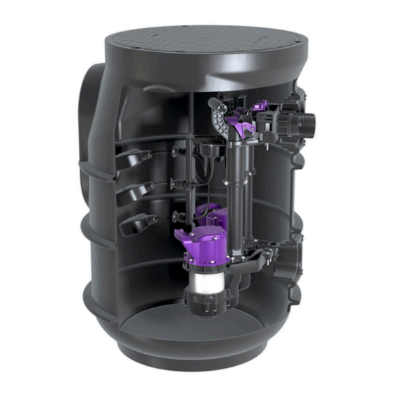
Description du produit Le poste est prévu pour une pose enterrée, dans le module rehausse fourni, à l’extérieur des bâtiments. Le poste prévoit l’installation ou de deux pompes (Mono/Duo). La structure des deux pompes et leur tubulure sont symétriques. Modèles : Mono Tronic (avec gestionnaire) Duo Tronic (avec gestionnaire) Accessoires optionnels...
  • Page 43 Caractéristiques techniques Indication / type de pompe GTF 600 GTF 1250 Poids 6 kg 10 kg Puissance P1 / P2 650W / 400 W 1,3 kW / 0,8 kW Régime 2750 tr/min 2700 tr/min Tension de service 230 volts ; 50 Hz 230 volts ;...
  • Page 44 Montage Réalisation de l'excavation et mise en place du système S’assurer de l’adéquation du produit (de la variante) avec les conditions environnantes (cf. "Utilisation conforme à l'usage prévu") et la profondeur de pose (cf. "Description du produit"). Définir l'angle de remblai β (env. 60°). Réalisation de l’excavation de manière à...
  • Page 45 Procéder au passage du câble Raccord du conduit pour câbles (variante A) Le conduit pour câbles doit présenter un arc maximal de 45°. Choisir une perceuse équipée d’une scie cloche adé- quate (réf. 500101). Procéder au perçage du conduit pour câbles dans le respect des instructions de la scie cloche.
  • Page 46 Monter le support à flotteur (Tronic) Mettre en place le support à flotteur. Bloquer le support à flotteur avec une fermeture rota- tive. Faire le raccordement électrique du gestionnaire (cf. "Raccordement électrique"). Montage du couvercle de protection Insérer le joint dans le regard correctement et aprés graisser le joint.
  • Page 47 Gestionnaire (Tronic) 4.9.1 Montage du gestionnaire Choisir l'emplacement prévu au montage en veillant aux points suivants : Proximité directe du gestionnaire d'une prise secteur avec terre. Installation correcte du câble de raccordement de la pompe et de l'interrupteur à flotteur à amener jusqu'au gestionnaire.
  • Page 48 Schéma de raccordement (Mono) (1) Raccordement au réseau (3) Interrupteur à flotteur (4) Alarme Brun Vert/ Jaune Gris Raccord pour le Raccord pour le jaune report d'alarme / report d'alarme / Blanc Vert contact sec contact sec Bleu Rose Libre externe (équi- externe (équi- Brun...
  • Page 49 Contact sec Il est possible de raccorder un contact sec au gestionnaire en tant que kit d’extension ; celui-ci est disponible dans les accessoires (réf. 80074). Celui-ci permet de raccorder l’appareil aux équipements techniques des bâtiments ou à d'autres accessoires comme par ex. au témoin lumineux (réf. 97715). Ètablir l'alimentation électrique.
  • Page 50 Mise en service La norme EN 12056-4 doit être respectée lors de la mise en service. Contrôle du système Vérifiez les points suivants avant la mise en service : Pose et montage corrects de la pompe/les pompes Fixation de tous les éléments démontables Étanchéité...
  • Page 51 Fonctionnement Mode manuel Voyant - Mode manuel Voyant - Mode manuel (Duo uniquement) Touche pompe 1 (10) Touche Pompe 2 (Duo uniquement) Le mode manuel peut être activé via la touche (9) / (10). La pompe n'est plus automatiquement mise en service dans ce cas.
  • Page 52 États de service Voyant Signal acous- Contact tique Description Action Vert rouge Orange Orange (inter- (4)/(5) valle) Hors service, pas de sur- Rétablir la tension de réseau veillance de la batterie En ordre de marche Cuve pleine, le pom- Aucune démarche n'est page démarre sous peu requise, il suffit de désacti- ver la pompe via l'actionne-...
  • Page 53 Arrêt du système Retirer la fiche de secteur du gestionnaire et patienter quelques secondes jusqu'à ce que l'alarme de panne de secteur soit activée (bref signal acoustique périodique et clignotement du voyant d'alarme (2)) Appuyer sur le bouton d'alarme (7) sans relâcher jusqu'à ce que le voyant d'alarme (2) ne clignote plus ;...
  • Page 54 Les eaux usées accumulées s’échappent ! Vérifier si les pièces de la pompe présentent des défor- mations et des dépôts. Au besoin, contacter le service KESSEL. S’assurer que les pièces mobiles se déplacent sans entrave. Procéder à un contrôle visuel des composants de la canalisation de refoulement.
  • Page 55 Détection du niveau Ouvrir la fermeture rotative. Retirer la sonde d'alarme (en option) et le support pour flotteur des supports. Nettoyer l'ensemble des pièces à l'eau, puis les essuyer. Remonter les composants dans le sens inverse du démontage. Dispositif antiretour ATTENTION Les eaux usées accumulées s’échappent ! Ouvrir la fermeture rotative.
  • Page 56 Cara cliente, caro cliente, in qualità di produttore premium di prodotti innovativi per la tecnica di drenaggio, KESSEL offre soluzioni di sistema integrate e un servizio orientato al cliente. Puntiamo sui massimi standard qualitativi e ci impegniamo coerentemente per la sosteni- bilità...
  • Page 57 Indicazioni sulle presenti istruzioni Le seguenti convenzioni illustrative semplificano l’orientamento: Simbolo Spiegazione vedere figura 1 Posizione numero 5 della figura accanto Passaggio procedurale nella figura Controllare se il funzionamento manuale è Presupposti per l’azione stato attivato. Premere OK. Passaggio procedurale L’impianto è...
  • Page 58 Sicurezza Avvertenze di sicurezza generali Durante l’installazione, il funzionamento, la manutenzione o la riparazione dell’impianto devono essere rispettate le norme antinfortunistiche, le norme e le direttive pertinenti e le prescrizioni delle aziende di energia e fornitura locali. AVVISO Mettere fuori tensione l’impianto! Accertare che i componenti elettrici siano separati dall’alimentazione di tensione durante i lavori.
  • Page 59 Persona Mansioni ammesse sugli impianti KESSEL Esercente Controllo visivo, sosti- tuzione della batteria Esperto (conosce e com- Svuotamento, puli- prende le istruzioni per l’uso)
  • Page 60 Descrizione del prodotto L’impianto è destinato all’installazione interrata, nel modulo del pozzetto in dotazione e al di fuori degli edifici. L’impianto è prodotto per la dotazione o con due pompe (Mono/Duo). Le strutture delle due pompe e le rispettive tubazioni sono simmetriche.
  • Page 61 Dati tecnici Indicazione / tipo di pompa GTF 600 GTF 1250 Peso 6 kg 10 kg Potenza P1 / P2 650 W / 400 W 1,3 kW / 0,8 kW Numero di giri 2750 min 2700 min Tensione di funzionamento 230 V;...
  • Page 62 Montaggio Scavo nel terreno e collocazione dell’impianto Accertare l’adeguatezza del prodotto (o della sua variante) alle condizioni ambientali (vd. "Uso conforme alla destinazione") e alla profondità di posa (vd. "Descri- zione del prodotto"). Determinare l’angolo di scarpata β (circa 60°). Praticare lo scavo con almeno 50 cm di sottofondo peri- metrale alla base.
  • Page 63 Realizzazione del passante per i cavi Collegamento per tubo vuoto per cavi (variante A) Il tubo vuoto per cavi deve essere realizzato con delle curve massime di 45°. Scegliere un trapano con una sega a tazza adeguata (cod.art. 500101). Praticare il foro per il tubo vuoto per cavi nel rispetto delle istruzioni della sega a tazza.
  • Page 64 Montaggio del supporto del galleggiante (Tronic) Installare il supporto del galleggiante. Bloccare il supporto del galleggiante con la chiusura gire- vole. Eseguire i collegamenti elettrici sulla centralina (vd. "Col- legamento elettrico"). Montaggio della piastra di copertura Posar la guarnizione nel pozzetto nella posizione corretta et ingrassare la guarnizione.
  • Page 65 Riempimento dello scavo Riempire lo scavo con del materiale di riempimento ade- guato (pietrisco frantumato con granulometria di 0/16, 50 cm di larghezza perimetrale), compattando adegua- tamente il materiale di riempimento stesso ogni 30 cm di spessore con gc ≥ 95% (ad esempio con una piastra vibrante).
  • Page 66 Fissare gli scarichi della trazione per tutti i cavi di collega- mento, momento di serraggio di 0,5 N m. Connettere il connettore della batteria alla batteria. Posare il cavo della batteria in modo che i LED non siano coperti o incastrati. Applicare il coperchio dell’alloggiamento e fissarlo, momento di serraggio delle viti di 1,2 N m.
  • Page 67 Schema di collegamento (Duo Tronic) (1) Voltaggio (3) Pompa delle acque di scarico (Duo) (4) Interruttore a galleggiante Marrone (C) Verde/ Verde/Giallo Marrone Giallo Giallo asse- gnato Bianco Verde Rosa (2) Pompa delle acque di sca- (5) Allarme asse- rico Collegamento Collegamento gnato...
  • Page 68 Messa in funzione Per la messa in funzione deve essere rispettata la norma EN 12056-4. Controllo dell’impianto Prima della messa in funzione devono essere verificati i seguenti punti: Installazione corretta della pompa/pompe Fissaggio di tutti gli elementi rimovibili Ermeticità dell’impianto Tensione di rete (massimo scostamento: ±10%) Sede corretta degli elementi per la rilevazione del livello L’impianto deve essere pulito e libero da detriti...
  • Page 69 Funzionamento Funzionamento manuale LED – funzionamento manuale LED – funzionamento manuale (solo con Duo) Tasto pompa 1 (10) Tasto pompa 2 (solo con Duo) Il funzionamento manuale può essere attivato con il tasto (9) / (10). Successivamente non avverrà alcuna accensione automatica della pompa delle acque di scarico.
  • Page 70 Stati di funzionamento Segnale acustico aran- Descrizione Compito verde Rosso aran- (inter- cio (3) vallo) (4)/(5) Fuori servizio, nessun moni- Ripristinare la ten- toraggio della batteria sione di rete elettrica Condizione di prontezza per il funzionamento Contenitore dell’impianto Nessuna misura necessaria, pieno, pompaggio di svuo- la pompa delle acque di sca- tamento entro breve tempo...
  • Page 71 Spegnimento dell’impianto Estrarre la spina di rete elettrica della centralina e atten- dere fino a che l’allarme per il black out viene attivato dopo un paio di secondi (breve segnale acustico ripetuto e lampeggio del LED d’allarme (2)). Premere il tasto (7) e tenerlo premuto fino a che il LED d’allarme (2) non lampeggia più, sono emessi quattro segnali acustici brevi, la centralina è...
  • Page 72 Fuoriuscita delle acque di scarico accumulatesi! Controllare la presenza di deformazioni e depositi sulle parti della pompa, eventualmente contattare il servizio KESSEL. Accertare la mobilità della parti mobili. Eseguire un controllo visivo dei componenti delle valvole. Pulire l’interruttore a galleggiante con un panno umido.
  • Page 73 Rilevazione del livello Aprire la chiusura girevole. Togliere la sonda di allarme (opzionale) e il supporto del galleggiante dai supporti. Immergere tutti i pezzi in un bagno d’acqua per pulirli e, quindi, tergerli con un panno umido. Rimontare i componenti in ordine inverso. Blocco antiriflusso ATTENZIONE Fuoriuscita delle acque di scarico accumulatesi!
  • Page 74 Beste klant, Als premium fabrikant van innovatieve producten voor de afwateringstechniek biedt KESSEL totale systeemoplossingen en klantgerichte service. Wij stellen hierbij maximale kwaliteitsnormen en zetten consequent in op duurzaamheid, niet alleen bij de productie van onze producten, maar ook met het oog op hun langdurige gebruik zetten wij ons in voor een permanente bescherming van u en uw eigendom.
  • Page 75 Informatie over deze handleiding De volgende weergaveconventies maken de oriëntatie eenvoudiger: Afbeelding Uitleg zie afbeelding 1 Positienummer 5 van nevenstaande afbeelding Handeling op de afbeelding … Controleren of de handmatige bediening is Voorwaarde voor de handeling ingeschakeld. Op OK drukken. Werkstap De installatie is bedrijfsklaar.
  • Page 76 Veiligheid Algemene veiligheidsinstructies Bij de installatie, het gebruik, het onderhoud of de reparatie van de installatie moeten de ongevalpreventievoorschriften, de relevante normen en richtlijnen en de voorschriften van de plaatselijke nutsbedrijven in acht worden genomen. LET OP Installatie vrijschakelen! Waarborgen dat de elektrische componenten tijdens de werkzaamheden losgekoppeld zijn van de voe- dingsspanning.
  • Page 77 De exploitant van de installatie is verplicht tot: het maken van een risicobeoordeling, het vaststellen en aantonen van gevarenzones, het uitvoeren van veiligheidsinstructies, het beveiligen tegen gebruik door onbevoegden. Persoon Vrijgegeven werkzaamheden bij KESSEL-installaties Exploitant Visuele controle, batterij vervangen Deskundige (kent en Leging, reiniging...
  • Page 78 Productomschrijving De installatie is bedoeld voor aardinbouw in de meege- leverde schacht, buiten gebouwen. De installatie wordt gemaakt om te worden voorzien van of twee pompen (Mono/Duo). De opbouw van de beide pompen en bijbeho- rend leidingwerk is symmetrisch. Uitvoeringen: Mono Tronic (met besturingskast) Duo Tronic (met besturingskast) Optionele toebehoren...
  • Page 79 Technische gegevens Informatie / soort pomp GTF 600 GTF 1250 Gewicht 6 kg 10 kg Vermogen P1 / P2 650 W / 400 W 1,3 kW / 0,8 kW Toerental 2750 min 2700 min Bedrijfsspanning 230 V; 50 Hz 230 V; 50 Hz Nominale stroom (per pomp) 2,9 A 5,4 A...
  • Page 80 Monteren Uitgraven van de bodem en plaatsing van de installatie Geschiktheid van product(variant) voor de omgevings- omstandigheden (zie "Reglementair gebruik") en inbouw- diepte (zie "Productomschrijving") controleren. Hellingshoek β (ca. 60°) bepalen. Gat graven, waarbij minstens 50 cm ruimte rond de basis van het reservoir moet worden vrijgehouden.
  • Page 81 Kabeldoorvoer maken Aansluiting mantelbuis (variant A) De mantelbuis moet met een maximale bocht van 45° worden uitgevoerd. Een boor met een passende gatenzaag (art.nr. 500101) kiezen. Het gat voor de mantelbuis volgens de handlei- ding van de gatenzaag boren. Afdichting voor de buisdoorvoer plaatsen Mantelbuis invetten en in doorvoerafdichting steken.
  • Page 82 Vlotterhouder monteren (Tronic) Vlotterhouder plaatsen. Vlotterhouder met draaisluiting vastzetten. Elektra op de besturingskast aansluiten (zie "Elektrische aansluiting"). Afdekplaat monteren Afdichting op de juiste positie in de schacht leggen en invetten. Afdekplaat plaatsen. Drie schroeven vastdraaien, corrosiebeschermingen op de schroefkoppen plaatsen. Lektest Zorgen dat de installatie geen stroom heeft, schoon is en vrij van gruis is.
  • Page 83 Besturingskast (Tronic) 4.9.1 Besturingskast monteren Montagepositie kiezen, daarbij moet het onderstaande gegarandeerd zijn: in de directe omgeving van de besturingskast is een geaard stopcontact aanwezig. De aansluitkabel van de afvalwaterpomp en vlotter- schakelaar kunnen volgens voorschrift geïnstalleerd en naar het besturingskast geleid worden. De besturingskast moet veilig en correct worden bevestigd.
  • Page 84 Aansluitschema (mono) (1) Netaansluiting (3) Vlotterschakelaar (4) Alarm bruin groen/ geel grijs Aansluiting voor Aansluiting voor geel extern alarm / extern alarm / groen potentiaalvrij con- potentiaalvrij con- blauw roze Niet tact (optioneel tact (optioneel bezet later uit te breiden later uit te breiden (2) Vuilwaterpomp bruin...
  • Page 85 Potentiaalvrij contact Op de besturingskast kan een potentiaalvrij contact worden aangesloten. Deze is beschikbaar als toebehoor (art.nr. 80074). Met dit contact kan het apparaat worden verbonden met de regeltechniek van het gebouw of andere toebehoren zoals de waarschuwingslamp (art.nr 97715). De voeding aansluiten Om het potentiaalvrij contact te gebruiken, drukt u tegelijkertijd de alarmtoets (2) en de toets voor handbediening (4) tien seconden in.
  • Page 86 Inbedrijfstelling Voor de inbedrijfstelling moet DIN 12056-4, in acht genomen worden. Controleren van de installatie Vóór de inbedrijfstelling moeten de volgende punten worden gecontroleerd. Correcte inbouw van de pomp(en) Vastzitten van alle wegneembare componenten Dichtheid van de installatie Netspanning (maximale afwijking ± 10%) Correcte positie van elementen t.b.v.
  • Page 87 Gebruik Handbediening Handbediening (led) Handbediening (led, alleen bij Duo) Toets pomp 1 (10) Toets pomp 2 (alleen bij Duo) De handbediening kan met de toets (9) / (10) worden geac- tiveerd. In dat geval vindt geen automatische inschakeling van de afvalwaterpomp meer plaats. Wordt handbediening tijdens afpompen ingeschakeld, scha- kelt de afvalwaterpomp uit.
  • Page 88 Bedrijfstoestanden Waar- schu- oranje wings- Omschrijving Maatregel groen rood oranje (4) / signaal (interval) Buiten bedrijf, geen Netspanning herstellen batterijbewaking Bedrijfsklaar Reservoir vol, deze wordt Geen maatregelen nodig, binnenkort leeggepompt de afvalwaterpomp kan met de toets (8) worden uitgeschakeld (zie "Hand- Reservoir wordt leeggepompt bediening", pagina 87) Het potentiaalvrij contact wordt geactiveerd (art.nr.
  • Page 89 Installatie uitschakelen Stekker van de besturingskast uit het stopcontact trek- ken en wachten tot het alarm voor stroomuitval na enkele seconden wordt geactiveerd (kort, herhaaldelijk waar- schuwingssignaal en de alarmled (2) knippert) Op de toets Alarm (7) drukken en zo lang ingedrukt hou- den tot de alarmled(2) niet meer knippert, er klinken vier korte waarschuwingssignalen en de besturingskast is uit- geschakeld...
  • Page 90 VOORZICHTIG Waterkolom loopt terug! Onderdelen van de pomp controleren op vervormin- gen en sediment, eventueel contact opnemen met de KESSEL-klantenservice. Controleren of de beweegbare delen makkelijk bewegen. Onderdelen van de armaturen visueel controleren. De vlotterschakelaar met een vochtige doek afnemen.
  • Page 91 Niveaudetectie Draaisluiting openen. Alarmsonde (optioneel) en vlotterhouder uit de houders nemen. Alle delen voor reiniging onderdompelen, daarna met vochtige doek afnemen. De componenten in omgekeerde volgorde weer monte- ren. Terugslagklep VOORZICHTIG Waterkolom loopt terug! Draaisluiting openen. Terugslagklep verwijderen. Terugslagklep reinigen. Onderdelen op slijtage controleren en in omgekeerde volgorde terugplaatsen.
  • Page 92 Szanowna Klientko, szanowny Kliencie, jako producent najwyższej klasy innowacyjnych produktów z zakresu techniki odwadniania firma KESSEL oferuje komplek- sowe rozwiązania systemowe i serwis odpowiadający potrzebom klientów. Stawiamy sobie najwyższe standardy jakościowe i konsekwentnie stawiamy na trwałość – nie tylko podczas produkcji naszych urządzeń, lecz również w zakresie ich długo- trwałego użytkowania dbamy o to, by stale gwarantowane było bezpieczeństwo użytkownika i jego mienia.
  • Page 93 Wskazówki dotyczące niniejszej instrukcji Poniższe formy oznaczeń ułatwiają orientację: Oznaczenie Objaśnienie patrz rysunek 1 Numer pozycji 5 na rysunku obok Krok postępowania na rysunku Sprawdzić, czy aktywowana została Warunek postępowania obsługa ręczna. Nacisnąć przycisk OK. Krok postępowania Urządzenie jest gotowe do pracy. Wynik postępowania Odniesienie do rozdz.
  • Page 94 Bezpieczeństwo Ogólne zasady bezpieczeństwa Podczas instalacji, obsługi, konserwacji lub naprawy urządzenia należy przestrzegać przepisów dotyczących zapobiega- nia wypadkom, odpowiednich norm i dyrektyw oraz przepisów miejscowych przedsiębiorstw energetycznych i dostawców mediów. NOTYFIKACJA Odłączyć urządzenie od zasilania! Upewnić się, że komponenty elektryczne są na czas prac odłączone od zasilania napięciem. OSTRZEŹENIE Elementy będące pod napięciem! Podczas prac przy przewodach i przyłączach elektrycznych należy przestrzegać, co następuje:...
  • Page 95 Użytkownik urządzenia jest zobowiązany do: sporządzenia oceny zagrożenia, wyznaczenia i oznakowania odpowiednich stref zagrożenia, przeprowadzenia instruktaży postępowania w razie niebezpieczeństwa, zabezpieczenia przed użyciem przez osoby nieupoważnione. Osoba Dozwolone czynności przy urządzeniach KESSEL Użytkownik Oględziny, inspek- cja, wymiana baterii Osoba o odpowiednich Opróżnianie, czysz- kwalifikacjach, (zna i rozu- czenie (wewnątrz),...
  • Page 96 Opis produktu Urządzenie przeznaczone jest do zabudowy w ziemi, w dostarczonej studzience, na zewnątrz budynków. Urządze- nie umożliwia zamontowanie (odpowiednio wersja Mono/ Duo). Konstrukcja obydwu pomp i ich orurowanie są syme- tryczne. Wersje: Mono Tronic (z urządzeniem sterującym) Duo Tronic (z urządzeniem sterującym) Osprzęt opcjonalny Przedłużka (nr art.
  • Page 97 Dane techniczne Dane / typ pompy GTF 600 GTF 1250 Ciężar 6 kg 10 kg Pobór mocy P1 / P2 650 W / 400 W 1,3 kW / 0,8 kW Prędkość obrotowa 2750 min 2700 min Napięcie robocze 230 V; 50 Hz 230 V;...
  • Page 98 Montaż Wykonanie wykopu i umieszczenie w nim urządzenia Upewnić się, że produkt (jego wariant) nadaje się do danych warunków otoczenia (patrz "Zastosowanie zgod- nie z przeznaczeniem") i głębokości zabudowy (patrz "Opis produktu"). Zdefiniować kąt nachylenia skarpy wykopu β (ok. 60°). Wykonać...
  • Page 99 Wykonanie przepustu kablowego Przyłączyć rurę osłonową na przewody elektryczne (wariant Rurę osłonową na przewody elektryczne należy wyko- nać z użyciem kształtek o kącie załamania nie więk- szym niż maks. 45°. Wybrać wiertarkę z pasującą otwornicą (nr art. 500101). Wywiercić otwór na przejście kablowe zgodnie z instruk- cją...
  • Page 100 Montaż uchwytu pływaków (Tronic) Wstawić uchwyt pływaków . Zamknąć uchwyt pływaków za pomocą blokady obroto- wej. Wykonać połączenia elektryczne na urządzeniu sterują- cym (patrz "Przyłącze elektryczne"). Montaż pokrywy Włożyć uszczelkę do studzienki, upewnić się, że jest w prawidłowej pozycji, następnie nasmarować. Nałożyć...
  • Page 101 Urządzenie sterujące (Tronic) 4.9.1 Montaż urządzenia sterującego Wybrać miejsce montażu, zwracając uwagę na następu- jące kwestie: Gniazdo wtykowe z obwodem ochronnym (bolcem) znajduje się w pobliżu urządzenia sterującego. Przewody pompy oraz pływakowego czujnika poziomu mogą zostać prawidłowo i estetycznie doprowadzone do urządzenia sterującego.
  • Page 102 Schemat połączeń (Mono) (1) Przyłącze sieciowe (3) Przełącznik pływakowy (4) Alarm Brązowy (C) Zie- Żółty Szary Przyłącze Przyłącze lony/żółty zewnętrznego zewnętrznego Biały Zielony podajnika podajnika Niebieski Różowy (Q) Nieuży- sygnału / kontaktu sygnału / kontaktu wany bezpotencjało- bezpotencjało- (2) Pompa ściekowa Brązowy wego (możliwość...
  • Page 103 Kontakt bezpotencjałowy Do urządzenia sterującego można podłączyć zestaw rozszerzający w formie kontaktu bezpotencjałowego, dostępnego jako osprzęt (nr art. 80074). Umożliwia on połączenie urządzenia z systemem zarządzania budynkiem lub innym osprzę- tem, np. lampą ostrzegawczą (nr art. 97715). Podłączyć do prądu. Aby aktywować...
  • Page 104 Uruchomienie Przy uruchamianiu przestrzegać normy PN-EN 12056-4. Kontrola urządzenia Przed uruchomieniem należy sprawdzić następujące punkty: Prawidłową zabudowę pompy Prawidłowe zamocowanie wszystkich wyjmowanych komponentów Szczelność urządzenia Napięcie sieciowe (maksymalne odchylenie ± 10 %) Prawidłowe osadzenie elementów do pomiaru poziomu Urządzenie jest czyste i wolne od gruzu budowlanego Uruchomienie (warianty Tronic z urządzeniem sterującym) Inicjalizacja urządzenia sterującego Zasilić...
  • Page 105 Eksploatacja Tryb ręczny LED – tryb ręczny LED – tryb ręczny (tylko w Duo) Przycisk pompa 1 (10) Przycisk pompa 2 (tylko w Duo) Tryb ręczny można aktywować przyciskiem (9) / (10). W tym trybie nie następuje automatyczne włączenie pompy ścieko- wej.
  • Page 106 Stany robocze Dioda LED Sygnał dźwię- poma- poma- zie- Czer- kowy Opis Środek rań- rań- lona wony (przery- czowa czowy wany) (4)/(5) Urządzenie nie działa, Przywrócić napięcie zasilające brak kontroli baterii Gotowość do pracy Zbiornik urządzenia jest pełny, Nie jest konieczne podję- w najbliższym czasie rozpocz- cie jakichkolwiek działań, nie się...
  • Page 107 Wyłączanie urządzenia Odłączyć wtyczkę sieciową urządzenia sterującego i odczekać kilka sekund, aż zainicjowany zostanie alarm awarii sieci (krótki, powtarzany sygnał dźwiękowy i miga- nie LED alarmu (2)) Wcisnąć przycisk alarmu (7) i przytrzymać go, aż LED alarmu (2) przestanie migać, zabrzmią cztery krótkie sygnały dźwiękowe, a urządzenie sterujące zostanie wyłączone.
  • Page 108 PRZESTROGA Nagromadzone ścieki wyciekną! Sprawdzić, czy części pompy nie są zdeformowane lub pokryte osadem, w razie potrzeby skontaktować się z serwisem firmy KESSEL. Sprawdzić czy wszystkie ruchome elementy poruszają się lekko i bez tarcia. Przeprowadzić oględziny elementów armatury. Wytrzeć wilgotną ścierką przełącznik pływakowy.
  • Page 109 Pomiar poziomu Otworzyć zamek obrotowy. Wyjąć sondę alarmową (opcjonalnie) i uchwyt pły- waka. Zanurzyć wszystkie części w kąpieli wodnej w celu ich oczyszczenia, a następnie przetrzeć wilgotną szmatką. Ponownie zmontować komponenty w odwrotnej kolejno- ści. Zawór zwrotny PRZESTROGA Nagromadzone ścieki wyciekną! Otworzyć...
  • Page 112 Registrieren Sie Ihr Produkt online, um von einer schnelleren Hilfe zu profitieren! http://www.kessel.de/service/produktregistrierung.html KESSEL AG, Bahnhofstr. 31, 85101 Lenting, Deutschland...

Ce manuel est également adapté pour:

Aqualift s basic duo tronic829851829811828851828811