Kessel LW 400 Mode D'emploi
Table des Matières
Les langues disponibles
Les langues disponibles
Liens rapides
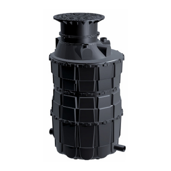
KESSEL Komfortschachtsystem
LW 400 / LW 800 / LW 1000
- zum Einbau ins Erdreich
Installation
Inbetriebnahme
der Anlage wurde durchgeführt von Ihrem Fachbetrieb:
Name/Unterschrift
Stand 2017/11
EINBAUANLEITUNG
LW 400
LW 800
Einweisung
Datum
LW 1000
Ort
Stempel Fachbetrieb
Produktvorteile
Modulares System
Zulassung Z-42.1-256
LW 1000
Zulassung Z-42.1-224
LW 400; LW 800
Grundwasserbeständig
bis 0,5 m
Teleskopisches Aufsatz-
stück für stufenlose
Höhenanpassung
Anbohrbar bis DN 150
D
Seite 1
GB
Page 25
F
Page 49
PL
Strona 73
Sach-Nr. 010-657
Chapitres
Table des Matières

Manuels Connexes pour Kessel LW 400


Sommaire des Matières pour Kessel LW 400
- Page 49 INSTRUCTIONS DE POSE Système de regard Komfort KESSEL LW 400 / LW 800 / LW 1000 - pour la pose à enterrer Avantages du produit Système modulaire Agrément Z-42.1-256 LW 1000 Agrément Z-42.1-224 LW 400; LW 800 Étanchéité aux eaux souterraines jusqu‘à...
- Page 50 Sommaire Introduction Description générale du produit .........................51 Informations d‘ordre général concernant ces instructions d‘utilisation et de maintenance ..51 Composants .................................52 Sécurité Utilisation conforme à l‘usage prévu ........................54 Sélection et qualification du personnel ......................54 Risques liés au produit .............................55 2.3.1 Risque d‘écrasement lié au jointoiement des segments du regard ............55 2.3.2 Risque lié...
-
Page 51: Introduction
Chère cliente, Cher client, Nous vous félicitons de votre achat d‘un produit KESSEL. Ce produit sera certainement en mesure de répondre à toutes vos attentes. Nous vous souhaitons une mise en place sans faille et réussie. Nous tentons de maintenir un niveau de qualité aussi élevé que possible de nos produits et avons évidemment besoin de votre collaboration. -
Page 52: Composants
Introduction Composants Fig. [1] Pos. Désignation Réf. n° Plaque de protection en fonte grise (GG), étanche aux eaux superficielles ; Cl. 860132 A, verrouillée Plaque de protection en fonte grise (GG), étanche aux eaux superficielles ; Cl. 860133 B, verrouillée Plaque de protection en fonte grise (GG), étanche aux eaux superficielles ; Cl. 860136 D, verrouillée Plaque de protection en fonte grise (GG), avec ventilation ;... - Page 53 Cône Ø 1070 860103 Cône Ø 1200 860102 Clavettes d‘assemblage (kit) pour LW 1000 860111 Clavettes d‘assemblage (kit) pour LW 800 840111 Clavettes d‘assemblage (kit) pour LW 400 850111 Joint à lèvres Ø 1070 860112 Pièce de rallonge 860101 Joint à lèvres Ø 1200 860113 Échelons d‘accès 860110 Segment inférieur...
-
Page 54: Sécurité
à tout recours à la garantie du fabricant. Les extensions ultérieures des systèmes de regard Kessel relèvent du domaine de compétence du service clientèle de Kessel. -
Page 55: Risques Liés Au Produit
Sécurité Risques liés au produit 2.3.1 Risque d‘écrasement lié au jointoiement des segments du regard Les segments du regard sont partiellement très lourds et encombrants. Attention au risque d‘écrasement des doigts et des mains pendant le jointoiement. Porter un équipement de protection personnelle (gants). Risques d‘écrasement et danger dû... -
Page 56: Montage
Montage Montage Généralités L‘assemblage des segments du regard doit se faire suivant la Fig. [1]. Observer ce qui suit : – L‘excavation doit être préparée pour recevoir le regard. – Contrôle de la profondeur du regard. S‘assurer que les segments du regard en l‘état monté correspondent à la profondeur de l‘excavation. -
Page 57: Schéma De Fonctionnement/Situation D'implantation
Montage Schéma de fonctionnement/situation d‘implantation Diamètre intérieur de 400 Fig. [2] Diamètre intérieur de 800 Fig. [3] Diamètre intérieur de 1000 Fig. [4] 2017/11 57 / 96 010-657... -
Page 58: Profondeurs D'implantation Lw 400
Montage Profondeurs d‘implantation LW 400 Fig. [5] DN 150 DN 200 DN 250 Segment inférieur fermé 700-1050 mm 745-1095 mm 795-1135 mm 749-1099 mm 1050-1400 mm 1095-1445 mm 1135-1485 mm 1099-1449 mm 1400-1750 mm 1445-1795 mm 1485-1835 mm 1449-1799 mm 1750-2100 mm 1795-2145 mm 1835-2185 mm 1799-2149 mm 2100-2450 mm 2145-2495 mm 2185-2535 mm 2149-2499 mm Profondeurs d‘implantation LW 800 Fig. [6] Pose du segment inférieur fermé... -
Page 59: Profondeurs D'implantation Lw 1000
Montage Profondeurs d‘implantation LW 1000 Fig. [7] Pose du segment inférieur fermé 1150-1650 mm 1650-2150 mm 2150-2650 mm 2650-3150 mm Préparation de l‘excavation La nature du sol et les matériaux pour le remblayage latéral de l‘excavation doivent répondre aux conditions suivantes : • Sol servant de support :plan, hauteur d‘env. 30 cm avec une couche de gravier/gravillons compactée*. •... -
Page 60: Pose Du Segment Inférieur
Montage Pose du segment inférieur • Disposer le segment inférieur horizontalement dans l‘excavation. Même de faibles écarts risquent de provoquer de fortes divergences jusqu‘au niveau supérieur des regards profonds. La surface destinée à recevoir le segment inférieur (fond de l‘excavation) doit entrer en contact plan avec le segment inférieur. •... -
Page 61: Raccordement Du Système De Conduites
Montage Raccordement du système de conduites 3.9.1 Raccordement du système de conduites du modèle LW 400 Établir les raccordements comme suit : – Entrée <30> – Sortie <31> À savoir si LW 400 : le canal du segment inférieur est composé de polypropylène (PP) et il donc impossible de le souder sur le tuyau en PE-HD. -
Page 62: Raccordement Du Système De Conduites Du Modèle Lw 800 / Lw 1000
Montage 3.9.2 Raccordement du système de conduites du modèle LW 800 / LW 1000 • Établir les raccordements comme suit : Entrée <30> ; Sortie <31> • Le segment inférieur fermé (p. ex. pour le canal fermé) doit être équipé d‘un renforcement par défaut à l‘usine du fait de sa résistance à... -
Page 63: Raccordement Du Système De Conduites Du Modèle Lw 800 / Lw 1000
Montage 3.9.3 Raccordement du système de conduites du modèle LW 800 / LW 1000 • Établir les raccordements comme suit : Entrée <30> ; Sortie <31> • Le segment inférieur fermé (p. ex. pour le canal fermé) doit être équipé d‘un renforcement par défaut à l‘usine du fait de sa résistance à... -
Page 64: Montage Des Échelons D'accès
Montage 3.10 Montage des échelons d‘accès Fig. [16] Disposer les échelons d‘accès <11> les uns au-dessus des autres par le haut dans les rails de guidage prévus à cet effet et les immobiliser avec des chevilles de sécurité (voir Fig. [8]). Les échelons d‘accès sont destinés aux systèmes de regard Komfort LW 800 et LW 1000. - Page 65 Montage • Graisser légèrement la face supérieure du joint d‘étanchéité. • Superposer les segments du regard de sorte à pouvoir disposer les échelons d‘accès les uns au-dessus des autres. • Relier les segments du regard suivant la Figure 17. • Poser la rehausse intercalaire ou le cône sur le segment inférieur. S‘assurer que les segments ont été...
-
Page 66: Montage De La Rehausse (Raccourcissement En Option)
Insérer le rehausse <20> ou <2>, l‘amener approximativement à la hauteur de montage souhaitée, fixer avec des anneaux serrants. • Procéder à l‘ajustage de précision à la hauteur définitive avec des vis d‘arrêt. LW 400 LW 800/1000 Fig. [22] Fig. [21]... -
Page 67: Variantes De Tampon
Marquer le pourtour suivant le dessin de sorte que la rehausse <20> ou <2> s‘insère d‘au moins 4 cm dans le cône <34>. • Scier avec une scie sauteuse (15°) <2>. Ébavurer les bords. LW 400 LW 800/1000 Fig. [23] Fig. [24] 3.13 Variantes de tampon Fig. -
Page 68: Remblayage De L'excavation
Montage 3.14 Remblayage de l‘excavation • Remblayer l‘excavation avec des matériaux de remblayage appropriés (grains d‘une grosseur de 0/16, hauteur de 50 cm autour du regard) en veillant à compacter les matériaux de remblayage tous les 30 cm (p. ex. avec un plaque vibrante) (<2> = calage de béton maigre). Respecter l‘angle d‘inclinaison de l‘excavation requis β... -
Page 69: 3.14.1 Regard Komfort Lw 400
Montage 3.14.1 Regard Komfort LW 400 Fig. [26] • En cas de pose dans des surfaces carrossables (Classe D), prévoir une dalle support armée d‘une épaisseur d‘env. 15 cm en béton <35> de classe B 35 d‘au moins 0,8 x 0,8 m pour la rehausse télescopique (Fig. [27]). La réalisation concrète de la dalle en béton est toujours fonction de la statique sur site. -
Page 70: 3.14.2 Regard Komfort Lw 800 / Lw 1000
Fig. [28] • La pose des systèmes de regard KESSEL dans des surfaces carrossables (Classe D) doit se faire suivant la superstructure standard (Directive pour la normalisation de la superstructure des voies de circulation [RSto] + Conditions contractuelles techniques supplémentaires et directives pour excavations de construction routière [ZTVE-StB], DIN 18196). -
Page 71: Caractéristiques Techniques
Caractéristiques techniques Caractéristiques techniques Profondeur maximale du regard maximum 5 m Étanchéité aux eaux souterraines 0,5 m Dimensions Voir Fig. [1] Poids Voir Fig. [1] Écart entre les échelons d‘accès et capacité portante Suivant EN 13598-2 / Règlement des associations professionnelles allemandes (BGV) C5 &...