Table des Matières

Publicité

Les langues disponibles
  • FR

Les langues disponibles

  • FRANÇAIS, page 32

Liens rapides

Einbau- und Betriebsanleitung
DE
DE
Einbau- und Betriebsanleitung....................................................................... 2
EN
EN
Installation and operating instructions.......................................................... 17
FR
FR
Instructions de pose et d'utilisation.............................................................. 32
IT
IT
Istruzioni per l'installazione e l'uso...............................................................47
NL
NL
Inbouw- en bedieningshandleiding............................................................... 62
PL
PL
Instrukcja zabudowy i obsługi.......................................................................77
2021/08
Pumpfix F
Pumpfix F
010-843_04

Publicité

Table des Matières
loading

Sommaire des Matières pour Kessel Pumpfix F SPZ 1000

  • Page 1 Pumpfix F Pumpfix F Einbau- und Betriebsanleitung Einbau- und Betriebsanleitung Einbau- und Betriebsanleitung............... 2 Einbau- und Betriebsanleitung............... 2 Installation and operating instructions............17 Installation and operating instructions............17 Instructions de pose et d’utilisation.............. 32 Instructions de pose et d’utilisation.............. 32 Istruzioni per l’installazione e l’uso...............47 Istruzioni per l’installazione e l’uso...............47 Inbouw- en bedieningshandleiding...............
  • Page 2: Table Des Matières

    Liebe Kundin, lieber Kunde, als Premiumhersteller von innovativen Produkten für die Entwässerungstechnik bietet KESSEL ganzheitliche Systemlösun- gen und kundenorientierten Service. Dabei stellen wir höchste Qualitätsstandards und setzen konsequent auf Nachhaltig- keit - nicht nur bei der Herstellung unserer Produkte, sondern auch im Hinblick auf deren langfristigen Betrieb setzen wir uns dafür ein, dass Sie und Ihr Eigentum dauerhaft geschützt sind.
  • Page 3: Hinweise Zu Dieser Anleitung

    Hinweise zu dieser Anleitung Folgende Darstellungskonventionen erleichtern die Orientierung: Darstellung Erläuterung siehe Abbildung 1 Positionsnummer 5 von nebenstehender Abbildung Handlungsschritt in Abbildung Prüfen, ob Handbetrieb aktiviert wurde. Handlungsvoraussetzung OK betätigen. Handlungsschritt Anlage ist betriebsbereit. Handlungsergebnis Querverweis auf Kapitel 2 siehe "Sicherheit", Seite 3 Fettdruck besonders wichtige oder sicherheitsrelevante Information Variante oder Zusatzinformation (z.
  • Page 4: Einleitung

    Alternativ kann auch eine chemikalienresistente Sonderlösung bezogen werden (indivi- dual@kessel.de). Um Frostsicherheit zu gewährleisten, muss die Anlage im Gebäude verbaut werden. Hinweis zur Gewährleistung Es darf nur für das Produkt vorgesehenes KESSEL-Zubehör verwendet werden. Bei Veränderungen am Produkt oder der Verwendung von nicht-originalem Zubehör erlischt die Gewährleistung. Lieferumfang Variante Pumpfix F zum Einbau in die Bodenplatte Verlängerungsstück (optional, max.
  • Page 5 Variante Pumpfix F freiliegend Pumpe Elektropack (E-Pack) Motorische Klappeneinheit Anschlüsse Zulauf-Seite Grundkörper Anschlüsse Auslauf-Seite Produktbeschreibung Die Rückstaupumpanlage ist für das Abpumpen von fäkalienfreiem und fäkalienhaltigem Abwasser vorgesehen. In den Grundkörper sind die Baugruppen für die Pumpen, die optische Rückstausonde und die motorisch angetriebene Rückstau- klappe eingebaut.
  • Page 6: Typenschild

    Funktionsprinzip Einbau in die Bodenplatte Rückstauebene Freiliegender Einbau Rückstauebene Typenschild Bezeichnung der Anlage Artikelnummer Anschlussspannung und Anschluss- frequenz, Stromaufnahmebereich Maximaler Förderstrom / Förderhöhe Betriebsart + Schutzart (IP) Seriennummer Revisionsstand der Hardware QR-Code 6 / 96 Einbau- und Betriebsanleitung 010-843_04...
  • Page 7: Technische Daten

    Technische Daten Pumpe SPZ 1000 Schwarzwasser-Tauchpumpe mit Schneidrad Angabe / Pumpenart SPZ 1000 Gewicht 10,5 kg Leistung P1 / P2 1,2 kW / 0,7 kW Drehzahl 2800 min Betriebsspannung 230 V; 50 Hz Nennstrom 5,2 A Förderleistung max. 12 m³/h Förderhöhe max.
  • Page 8: Montage

    Montage Einbaubedingungen überprüfen Voraussetzungen zu Einbauort beachten: Ausführung der Bauwerksabdichtung (Weiße oder Schwarze Wanne) berücksichtigen, siehe entsprechende Einbaubei- spiele. Höhe des Bodenaufbaus bzw. Stärke der Bodenplatte kalkulieren, die maximale Tiefe darf nicht überschritten werden. Ggf. ist ein Verlängerungsstück (Zubehör, Art.-Nr. 83075 oder 83073) erforderlich. Prüfen, ob die Anlage in Boden mit drückendem Wasser verbaut wird.
  • Page 9 5.1.2 Einbaubeispiel Schwarze Wanne (Bodenplatte mit Trennlage) 1 Pumpfix F 2 Dichtungsset Art.-Nr. 83073: Ver- längerungsstück mit Flansch und Gegenflansch (für den Anschluss an eine bauseitige Dichtbahn) 3 Verlängerungsstück Art.-Nr. 83070 a Bodenbelag f Schutzbeton b Estrich g Schaltgerät c Dämmung h Kabelleerrohr d Betonboden BWS* Bemes-...
  • Page 10 Einbau in die Bodenplatte Schwarze Wanne Bauseitige Dichtungsbahn (3) zwischen Pressdichtungs- flansch (4) und Gegenflansch (2) einklemmen und mit den Schrauben (1) verschrauben. Weiße Wanne Dichtung (6) in Grundkörper (7) einlegen und auf Sitz der Dichtung achten. Oberseite der Dichtung fetten. Verlängerungsstück mittiger Flansch (5) einschieben und in Position bringen.
  • Page 11: Kabelleerrohr Montieren

    (DN50) an den Grundkörper heranführen und montieren. Für Richtungsänderungen max. 45° Bögen verwenden. Sollte das Kabelleerrohr im Aufsatzstück installiert wer- den, muss dieses mit der KESSEL Sägeglocke Art.-Nr. 500101 oder einer handelsüblichen Sägeglocke Ø 60 mm und der Rohrdurchführungsdichtung Art.-Nr. 850114 aus- geführt werden.
  • Page 12: Aufsatzstück Montieren

    Aufsatzstück montieren Je nach Einbautiefe muss das Aufsatzstück (1) (Einsteck- tiefe des Aufsatzstückes) ggf. abgelängt bzw. mit Ausspa- rungen (4) für die Leitungsverbindungen, die seitlich in den Grundkörper (3) hineingeführt werden, versehen werden. Das Aufsatzstück (1) darf mit maximal 2 Verlängerungs- stücken verlängert werden, damit zu Wartungszwecken noch bis zum Grundkörper hinunter gegriffen werden kann.
  • Page 13: Inbetriebnahme

    Inbetriebnahme Bei Erstinbetriebnahme prüfen, ob die im Kapitel Montage erläuterten Schritte ordnungsgemäß ausgeführt wurden. Funktionsprüfung Pumpe und Sensorik Am Schaltgerät die Taste "Klappe" betätigen. Prüfen, ob Rückstauklappe zufährt. (Motorengeräusch, Hebel legt sich selbsttätig um). Angeschlossenen Wasserversorger laufen lassen. Prüfen, ob Pumpe anläuft und hausseitig anstauendes Wasser abpumpt. Wasserversorger abdrehen.
  • Page 14: Wartung

    Wartung ACHTUNG Anlage freischalten! Sicherstellen, dass die elektrischen Komponenten während der Arbeiten von der Spannungsversorgung getrennt sind. Wartungsintervall Die Wartung muss gemäß Normvorgabe in folgenden Zeitabständen erfolgen: 1/2-jährlich (EN 13564) Vorbereitung der Wartung Wartung nur durchführen, wenn kein Rückstau anliegt. Funktionskontrolle der Anlage durchführen falls nicht bereits geschehen, siehe "Inbetriebnahme und Funkti- onskontrolle"...
  • Page 15 Niveauerfassung demontieren Beide Schrauben (TX25) herausschrauben. Sonde mit Halterung herausziehen. Vorgehensweise für zweite Sonde wiederholen. Verriegelungsdeckel und Klappe demontieren Beide Schnellverschlüsse öffnen. Verriegelungsdeckel mit Motor abnehmen. Halteklip abziehen und Rückstauklappe herausneh- men. Prüfen, ob Rückflussverhinderer vollständig schließt. Dazu probeweise Klappe betätigen und auf "Plopp"- Geräusch achten.
  • Page 16: Hilfe Bei Störungen

    Alle demontierten Komponenten im Wasserbad reinigen (ggf. mit Bürste). Komponenten einfetten Die Dichtungen des Verriegelungsdeckels und des Ein- schiebeteils (zum Grundkörper hin) dürfen ausschließlich mit KESSEL-Hochleistungsfett (Art.-Nr. 681001) eingefet- tet werden. Folgende Komponenten müssen mit KESSEL-Hochleis- tungsfett gefettet werden: Dichtflächen am Einschiebeteil und Verriegelungsdeckel Dichtung am Schwenkanschluss Rückstauklappe und motorischen Hebel dort einfetten,...
  • Page 17 Dear Customer, As a premium manufacturer of innovative products for draining technology, KESSEL offers integrated system solutions and customer-oriented service. In doing so, we set the highest quality standards and focus firmly on sustainability - not only with the manufacturing of our products, but also with regard to their long-term operation and we strive to ensure that you and your property are protected over the long term.
  • Page 18: Notes On This Manual

    Notes on this manual The following conventions make it easier to navigate the manual: Symbol Explanation See Figure 1 Position number 5 from the adjacent figure Action step in figure Check whether manual operation has been Prerequisite for action activated. Press OK.
  • Page 19: Personnel Qualification

    Note on warranty Only KESSEL accessories designed for the product may be used. If any modifications are made to the product or non- original accessories are used, the warranty becomes null and void.
  • Page 20: Product Description

    Pumpfix F exposed version Pump Power pack (E-pack) Motor-driven flap unit Inlet side connections Drain body Outlet side connections Product description The backwater pumping station has been designed for pumping faecal and faecal-free wastewater. The assemblies for the pumps, the optical probe and the motor-driven backwater flap are installed in the drain body. In normal operation, the wastewater passes through the backwater pumping station to the sewage channel without any backwater occurrence.
  • Page 21: How It Works

    How it works Floor slab installation Backwater level Exposed installation Backwater level Type plate Name of the system Article number Connection voltage and connection fre- quency, current consumption range Maximum delivery rate / pumping height Operating mode + protection rating (IP) Serial number Hardware revision status QR code...
  • Page 22: Technical Data

    Technical data Pump SPZ 1000 Submersible blackwater pump with macerator Information / pump type SPZ 1000 Weight 10.5 kg Power P1 / P2 1.2 kW / 0.7 kW Speed 2800 rpm Operating voltage 230 V; 50 Hz Rated current 5.2 A Max.
  • Page 23: Installation

    Installation Check the installation conditions Observe the prerequisites regarding the installation location: Take the building waterproofing version into account (white tank or bituminous membrane), see corresponding installation examples. Calculate the height or thickness of the floor slab, the maximum depth must not be exceeded. An extension section (accessories, art.
  • Page 24 5.1.2 Installation example bituminous membrane (floor slab with separating layer) 1 Pumpfix F 2 Seal set art. no. 83073: extension section with flange and counter- flange (for connection to an on-site sealing sheet) 3 Extension section art. no. 83070 a Floor covering f Protective con- crete b Screed...
  • Page 25 Floor slab installation Bituminous membrane Clamp the waterproofing membrane (3) on site between the pressure sealing flange (4) and the counter-flange (2) and screw together using the screws (1). White tank Insert the seal (6) into the drain body (7) and ensure that the seal fits properly.
  • Page 26: Ventilation Pipe

    Use max. 45° bends for changes in direction. If the cable conduit is to be installed in the upper section, it must be carried out with the KESSEL hole saw art. no. 500101 or a standard hole saw Ø 60 mmand the pipe penetration seal art.
  • Page 27: Installing The Upper Section

    Installing the upper section Depending on installation depth, the upper section (1) (insertion depth of the upper section) may have to be cut to length or have recesses (4) made in it for the cable connec- tions, which are fed into the side of the drain body (3). The upper section (1) may only be extended by a maxi- mum of 2 extension sections, so that it remains possible to reach into the drain body for maintenance purposes.
  • Page 28: Commissioning

    Commissioning For the initial startup, check whether the steps explained in the Assembly chapter have been carried out properly. Functional test of pump and sensors Press the “Flap” button at the control unit. Check whether the wastewater flap closes. (Motor noise, lever switches automatically). Let the connected water supplier run.
  • Page 29: Maintenance

    Maintenance NOTICE Disconnect system from energy sources! Ensure that the electrical components are disconnected from the electrical power supply during the work. Maintenance interval According to standard specifications, maintenance must be carried out at the following intervals: Every 6 months (EN 13564) Preparing maintenance Only carry out maintenance if there is no backwater present.
  • Page 30 Remove the level detection Unscrew both screws (TX25). Pull the probe out with bracket. Repeat the procedure for the second probe. Dismantle the lockable cover and flap Open both quick-release closures. Remove the lockable cover with motor. Pull off the retaining clip and remove the backwater flap.
  • Page 31: Troubleshooting

    The seals of the lockable cover and the slide-in flap hous- ing (towards the drain body) may only be greased with KESSEL high-performance grease (art. no. 681001). The following components must be greased with KESSEL high-performance grease: Sealing faces on the slide-in flap housing and lockable...
  • Page 32 Chère cliente, cher client, En qualité de producteur de pointe de produits novateurs dans le domaine de la technique d’assainissement, KESSEL pro- pose des réponses systématiques globales et un service orienté aux besoins de la clientèle. Nous misons simultanément sur les normes de qualité les plus élevées et une durabilité conséquente – non seulement lors de la fabrication de nos pro- duits, mais également pour leur utilisation à...
  • Page 33: Informations Spécifiques Aux Présentes Instructions

    Informations spécifiques aux présentes instructions Les conventions de représentation suivantes facilitent l’orientation : Représentation Explication voir figure 1 Numéro de repère 5 de la figure ci-contre Action de la figure Vérifier si le mode manuel a été activé. Condition de réalisation de l’action Valider <OK>.
  • Page 34: Introduction

    Remarque concernant la garantie Utiliser uniquement les accessoires prévus pour le produit KESSEL. Le fabricant décline tout recours à sa garantie en cas de modifications effectuées sur le produit ou de l’utilisation d’accessoires non originaux. Détail de livraison Variante Pumpfix F pour pose encastrée en dalle...
  • Page 35: Description Du Produit

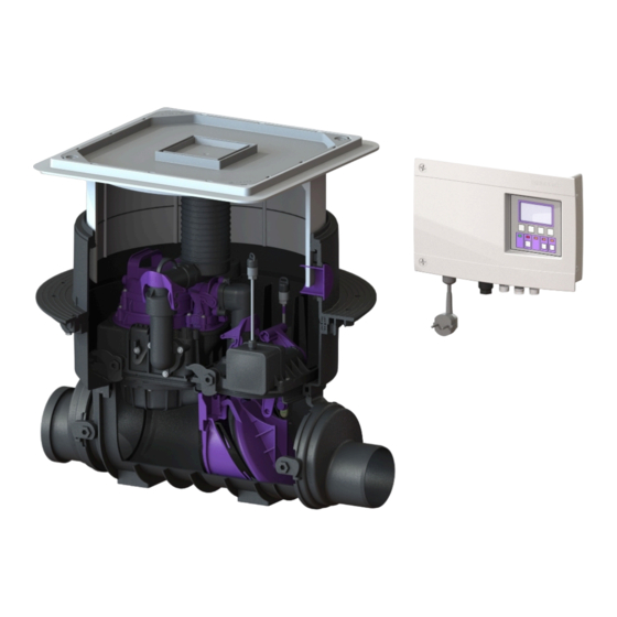
    Variante Pumpfix F hors sol Pompe Pack électrique Unité motorisée du clapet Raccords côté arrivée Corps de base Raccords côté sortie Description du produit Le clapet antiretour avec pompe est destiné au refoulement des eaux grises et eaux vannes. Les composants des pompes, la sonde optique et le clapet antiretour à...
  • Page 36: Principe De Fonctionnement

    Principe de fonctionnement Pose encastrée en dalle Niveau des plus hautes eaux Pose hors sol Niveau des plus hautes eaux Plaque signalétique Désignation du poste N° de référence Tension et fréquence d'alimen- tation, puissance absorbée Débit maximal / hauteur de relevage Mode de fonctionnement + type de protection (IP) Numéro de série Version de mise à...
  • Page 37: Caractéristiques Techniques

    Caractéristiques techniques Pompe SPZ 1000 Pompe submersible pour eaux vannes avec roue porte-lame Indication / type de pompe SPZ 1000 Poids 10,5 kg Puissance P1 / P2 1,2 kW / 0,7 kW Régime 2 800 tr/min Tension de service 230 volts ; 50 Hz Courant nominal 5,2 A Capacité...
  • Page 38: Montage

    Montage Vérifier les conditions de montage Observer les conditions relatives à l’emplacement de montage : Tenir compte de l’exécution de l’étanchéité de l’ouvrage (cuve blanche ou noire), voir les exemples de montage corres- pondants. Calculer la hauteur de la structure du sol ou l’épaisseur de la dalle. Ne pas dépasser la profondeur maximale. Une ral- longe de rehausse peut éventuellement être requise (accessoires, réf.
  • Page 39: Exemple De Montage " Cuve Noire " (Dalle Avec Couche De Séparation)

    5.1.2 Exemple de montage « cuve noire » (dalle avec couche de séparation) 1 Pumpfix F 2 Ensemble de joints réf. 83073 : ral- longe de rehausse avec bride et contre-bride (à raccorder à une bande d’étanchéité sur site) 3 Rallonge de rehausse, réf. 83070 a Revêtement de f Béton de pro- tection...
  • Page 40: Pose Encastrée En Dalle

    Pose encastrée en dalle Cuve noire Serrer la bande d'étanchéité à prévoir sur site (3) entre la bride de compression (4) et la contre-bride (2) et fixer avec des vis (1). Cuve blanche Poser le joint (6) dans le corps de base (7) et veiller au logement correct du joint.
  • Page 41: Conduite D'aération Et De Ventilation

    Conduite d'aération et de ventilation En cas de pose hors sol, s’assurer que la vanne d’aération et de ventilation prémontée (filtre à charbon actif (1) inclus) est fermement vissée. En cas de pose dans le regard, démonter la vanne d’aération et de ventilation et guider le tuyau d’aération et de ventila- tion au-dessus du niveau des plus hautes eaux.
  • Page 42: Montage De La Rehausse

    Montage de la rehausse En fonction de la profondeur de pose, la rehausse (1) (pro- fondeur d'insertion de la rehausse) peut éventuellement être raccourcie et pourvue d'évidements (4) pour les raccords de tuyauterie à introduire latéralement dans le corps de base (3).
  • Page 43: Mise En Service

    Mise en service Lors de la première mise en service, s’assurer que toutes les étapes du chapitre Montage ont été correctement exécu- tées. Contrôle du fonctionnement de la pompe et des capteurs Actionner la touche « Clapet » sur le gestionnaire. Vérifier que le clapet antiretour se ferme.
  • Page 44: Maintenance

    Maintenance AVIS Activer le système ! S'assurer que l'alimentation électrique est coupée pendant les travaux. Intervalle de maintenance Procéder à la maintenance selon les prescriptions de la norme en respectant au moins les intervalles suivants : Une fois tous les six mois (EN 13564) Préparation de la maintenance Vérifier l’absence de reflux avant de procéder à...
  • Page 45 Démontage de la détection du niveau Dévisser les deux vis (TX25). Retirer la sonde avec son support. Procéder de la même manière pour la seconde sonde. Démonter le couvercle de verrouillage et le clapet. Ouvrir les deux fermetures rapides. Retirer le couvercle de verrouillage avec le moteur. Retirer le clip de maintien et enlever le clapet antire- tour.
  • Page 46: Graisser Les Composants

    être enduits de graisse haute performance KESSEL (réf. 681001). Les composants suivants doivent être graissés avec la graisse haute performance KESSEL : Surfaces d'étanchéité sur le support battant et le cou- vercle de verrouillage Joint sur le raccord pivotant Graisser le clapet antiretour et le levier motorisé...
  • Page 47 Cara cliente, caro cliente, in qualità di produttore premium di prodotti innovativi per la tecnica di drenaggio, KESSEL offre soluzioni di sistema integrate e un servizio orientato al cliente. Puntiamo sui massimi standard qualitativi e ci impegniamo coerentemente per la sosteni- bilità...
  • Page 48: Indicazioni Sulle Presenti Istruzioni

    Indicazioni sulle presenti istruzioni Le seguenti convenzioni illustrative semplificano l’orientamento: Simbolo Spiegazione vedere figura 1 Posizione numero 5 della figura accanto Passaggio procedurale nella figura Controllare se il funzionamento manuale è Presupposti per l’azione stato attivato. Premere OK. Passaggio procedurale L’impianto è...
  • Page 49: Introduzione

    (individual@kessel.de). Per garantire la sicurezza antigelo, l’impianto deve essere installato nell’edificio. Indicazione sulla garanzia È possibile utilizzare solo gli accessori KESSEL previsti per il prodotto. Le modifiche al prodotto o l’uso di accessori non originali annullano la garanzia. In dotazione Variante Pumpfix F per l’installazione a pavimento...
  • Page 50: Descrizione Del Prodotto

    Variante Pumpfix F non interrata Pompa Pacchetto elettrico (E-Pack) Unità clapet motorizzato Collegamenti lato d’entrata Corpo base Collegamenti lato d’uscita Descrizione del prodotto La valvola antiriflusso con stazione di pompaggio è destinata al pompaggio di svuotamento delle acque di scarico con e senza sostanze fecali.
  • Page 51: Principio Di Funzionamento

    Principio di funzionamento Installazione a pavimento Livello di riflusso Installazione non interrata Livello di riflusso Targhetta Denominazione dell’impianto Codice articolo Tensione e frequenza di collegamento, gamma di assorbimento di corrente Portata / Altezza di pompaggio massime Tipo di funzionamento + tipo di protezione (IP) Numero di serie Stato di revisione dell’hardware Codice QR...
  • Page 52: Dati Tecnici

    Dati tecnici Pompa SPZ 1000 Pompa ad immersione per acque nere con lama a disco Indicazione / tipo di pompa SPZ 1000 Peso 10,5 kg Potenza P1 / P2 1,2 kW / 0,7 kW Numero di giri 2800 min Tensione di funzionamento 230 V;...
  • Page 53: Montaggio

    Montaggio Controllo delle condizioni di installazione Tenere conto dei requisiti relativi al luogo di installazione: Tenere conto della variante dell’impermeabilizzazione dell’opera edile (vasca nera o bianca); vedere i rispettivi esempi di installazione. Calcolare l’altezza della pavimentazione ovvero lo spessore del pavimento; la profondità massima non deve essere supe- rata.
  • Page 54 5.1.2 Esempio di installazione con vasca nera (lastra di cemento con strato di separazione) 1 Pumpfix F 2 Kit di guarnizioni, codice articolo 83073: prolunga con flangia e con- tro-flangia (per il collegamento a una guaina impermeabilizzante del cliente) 3 Prolunga, codice articolo 83070 a Rivestimento f Calcestruzzo del pavimento...
  • Page 55: Installazione A Pavimento

    Installazione a pavimento Vasca nera Serrare il materiale impermeabilizzante (3) tra la flangia di tenuta a pressione (4) e la contro-flangia (2) e avvitare con le viti (1). Vasca bianca Posare la guarnizione per condotto del tubo (6) nel corpo base (7) prestando attenzione alla sede della guarnizione per condotto del tubo.
  • Page 56 Se il tubo per cavi dovesse essere installato nel rialzo, l’installazione dovrà essere eseguita con la sega a tazza KESSEL, codice articolo 500101, o con una comune sega a tazza Ø 60 mm e con la guarnizione per passante tubi 850114.
  • Page 57: Montaggio Del Rialzo

    Montaggio del rialzo A seconda della profondità di posa, il rialzo (1) (profondità di innesto del rialzo) dovrà essere eventualmente accorciato o dotato di aperture (4) per il collegamenti dei condotti che verranno inseriti lateralmente nel corpo base (3). Il rialzo (1) potrà essere allungato al massimo con 2 pro- lunghe, in modo che per i lavori di manutenzione sia sem- pre possibile raggiungere il corpo base sottostante.
  • Page 58: Messa In Funzione

    Messa in funzione In occasione della prima messa in funzione, controllare che i passi descritti nel capitolo “Montaggio” siano stati eseguiti regolarmente. Verifica del funzionamento della pompa e della sensoristica Azionare il tasto “Clapet” sulla centralina. Controllare che il clapet antiriflusso si chiuda. (Rumore del motore, la leva si sposta autonomamente). Aprire l’alimentazione idrica collegata.
  • Page 59: Manutenzione

    Manutenzione AVVISO Mettere fuori tensione l’impianto! Accertare che i componenti elettrici siano separati dall’alimentazione di tensione durante i lavori. Intervallo di manutenzione La manutenzione deve essere eseguita secondo le indicazioni della norma almeno nei seguenti intervalli: Semestralmente (EN 13564) Preparazione della manutenzione Eseguire la manutenzione solo in assenza di riflusso.
  • Page 60 Smontaggio della rilevazione del livello Svitare entrambe le viti (TX25). Estrarre la sonda con il supporto. Ripetere la procedura per la seconda sonda. Smontaggio del coperchio e del clapet Aprire entrambe le chiusure rapide. Rimuovere il coperchio con il motore. Estrarre la clip di tenuta e il clapet antiriflusso.
  • Page 61: Assemblaggio Dei Componenti

    Ingrassaggio dei componenti Le guarnizioni del coperchio e dell’elemento inseribile (fino al corpo base) devono essere ingrassate esclusiva- mente con il grasso ad alte prestazioni KESSEL (codice articolo 681001). I seguenti componenti devono essere ingrassati con il grasso ad alte prestazioni KESSEL: Superfici di tenuta sul porta paletta e sul coperchio Guarnizione per condotto del tubo sull’attacco girevole...
  • Page 62 Beste klant, Als premium fabrikant van innovatieve producten voor de afwateringstechniek biedt KESSEL totale systeemoplossingen en klantgerichte service. Wij stellen hierbij maximale kwaliteitsnormen en zetten consequent in op duurzaamheid, niet alleen bij de productie van onze producten, maar ook met het oog op hun langdurige gebruik zetten wij ons in voor een permanente bescherming van u en uw eigendom.
  • Page 63: Informatie Over Deze Handleiding

    Informatie over deze handleiding De volgende weergaveconventies maken de oriëntatie eenvoudiger: Afbeelding Uitleg zie afbeelding 1 Positienummer 5 van nevenstaande afbeelding Handeling op de afbeelding … Controleren of de handmatige bediening is Voorwaarde voor de handeling ingeschakeld. Op OK drukken. Werkstap De installatie is bedrijfsklaar.
  • Page 64: Introductie

    Als alternatief kan er ook een chemicaliënresistente maatoplossing worden geleverd (individual@kessel.de). Om vorstschade te voorkomen, moet de installatie binnenshuis worden ingebouwd. Garantie-informatie Er mogen alleen voor het product bedoelde KESSEL-toebehoren worden gebruikt. Bij wijzigingen aan het product of het gebruik van niet-originele toebehoren vervalt de garantie. Leveringsomvang Variant Pumpfix F voor vloerinbouw Verlengstuk (optioneel, max.
  • Page 65: Productomschrijving

    Variant Pumpfix F vrijliggend Pomp Elektropakket (E-Pack) Motorische klepeenheid Aansluitingen toevoerkant Basiselement Aansluitingen uitloopkant Productomschrijving De terugstuwpompinstallatie is bedoeld voor het wegpompen van fecaliënvrij en fecaliënhoudend afvalwater. De modules voor de pompen, de optische sonde en de motorische terugstuwklep zijn in het basiselement ingebouwd. Tijdens normale werking loopt het afvalwater zonder opstuwing door de terugstuwpompinstallatie het afvalwaterriool in.
  • Page 66 Werkingsprincipe Vloerinbouw Terugstuwniveau Vrijliggende inbouw Terugstuwniveau Typeplaatje Aanduiding van de installatie Artikelnummer Aansluitspanning en aansluit- frequentie, stroomverbruik Maximaal debiet/opvoerhoogte Bedrijfsmodus + beschermingsklasse (IP) Serienummer Revisiestand van de hardware QR-code 66 / 96 Inbouw- en bedieningshandleiding 010-843...
  • Page 67: Technische Gegevens

    Technische gegevens Pomp SPZ 1000 Dompelpomp met snijwerk voor zwartwater Informatie / soort pomp SPZ 1000 Gewicht 10,5 kg Vermogen P1 / P2 1,2 kW / 0,7 kW Toerental 2800 min Bedrijfsspanning 230 V; 50 Hz Nominale stroom 5,2 A Afvoercapaciteit max.
  • Page 68: Monteren

    Monteren Inbouwvoorwaarden controleren Voorwaarden voor de inbouwlocatie in acht nemen: Rekening houden met de variant van de afdichting (witte of zwarte inbouwmethode), zie de bijbehorende inbouwvoorbeel- den. De hoogte van de bodemopbouw respectievelijk de sterkte van de vloerplaat uitrekenen; de maximale diepte mag niet worden overschreden.
  • Page 69 5.1.2 Inbouwvoorbeeld voor zwarte inbouwmethode (vloerplaat met scheidingslaag) 1 Pumpfix F 2 Set afdichtingen art.nr. 83073: ver- lengstuk met flens en contraflens (voor het aansluiten van een afdicht- baan op de inbouwlocatie) 3 Verlengstuk, art.nr. 83070 a Vloerafwerking f Waterdicht beton b Afwerkvloer g Besturingskast...
  • Page 70 Vloerinbouw Zwarte inbouwmethode Afdichtingsbaan (3) op de inbouwlocatie tussen de pers- afdichtingsflens (4) en de tegenflens (2) klemmen en met de schroeven (1) vastschroeven. Witte inbouwmethode Afdichting (6) in het basiselement (7) leggen en zorgen dat zij goed is geplaatst. Bovenkant van de afdichting invetten.
  • Page 71: Mantelbuis Monteren

    Voor richtingveranderingen bochten van maximaal 45° gebruiken. Als de mantelbuis in het opzetstuk wordt gemonteerd, moet dat met de KESSEL-gatenzaag (art.nr. 500101) of een gangbare gatenzaag (Ø 60 mm) en een afdichting voor buisdoorvoer (art.nr. 850114) worden uitgevoerd. Het aansluiten van elektrische leidingen wordt in de mee- geleverde besturingskasthandleiding beschreven.
  • Page 72: Opzetstuk Monteren

    Opzetstuk monteren Afhankelijk van de inbouwdiepte moet het opzetstuk (1) (insteekdiepte van het opzetstuk) eventueel worden inge- kort of worden uitgerust met uitsparingen (4) voor de leiding- verbindingen die horizontaal in het basiselement (3) worden doorgevoerd. Het opzetstuk (1) mag met maximaal twee verlengstuk- ken worden verlengd, zodat het basiselement bij onder- houd nog kan worden bereikt.
  • Page 73: Inbedrijfstelling

    Inbedrijfstelling Bij de eerste inbedrijfstelling controleren of de in het hoofdstuk Montage beschreven stappen correct zijn uitgevoerd. Functionele controle van de pomp en sensoren Op de besturingskast op de knop “Klep” drukken. Controleren of de terugstuwklep sluit. (Er klinkt motorgeluid, de hendel draait automatisch.) De aangesloten waterleiding opendraaien.
  • Page 74: Onderhoud

    Onderhoud LET OP Installatie vrijschakelen! Waarborgen dat de elektrische componenten tijdens de werkzaamheden losgekoppeld zijn van de voe- dingsspanning. Onderhoudsinterval Het onderhoud moet conform de normen met de volgende tussenpozen gebeuren: halfjaarlijks (EN 13564) Voorbereiding van het onderhoud Onderhoud alleen uitvoeren als er geen sprake is van terugstuwing.
  • Page 75 Niveaudetectie demonteren Draai beide schroeven (TX25) eruit. Trek de sonde met de houder eruit. Herhaal de procedure voor de tweede sonde. Vergrendelbaar deksel en klep demonteren Beide snelsluitingen openen. Vergrendelbaar deksel met de motor verwijderen. Bevestigingsclip losmaken en de terugstuwklep verwijde- ren.
  • Page 76: Hulp Bij Storingen

    (eventueel met een borstel). Onderdelen invetten De afdichtingen van het vergrendelbare deksel en het inschuifgedeelte (voor het basiselement) mogen alleen met hoogwaardig KESSEL-vet (art.nr. 681001) worden ingevet. De volgende onderdelen moeten met hoogwaardig KESSEL-vet worden ingevet: Afdichtingsoppervlakten bij het inschuifgedeelte en het...
  • Page 77 Szanowna Klientko, szanowny Kliencie, jako producent najwyższej klasy innowacyjnych produktów z zakresu techniki odwadniania firma KESSEL oferuje komplek- sowe rozwiązania systemowe i serwis odpowiadający potrzebom klientów. Stawiamy sobie najwyższe standardy jakościowe i konsekwentnie stawiamy na trwałość – nie tylko podczas produkcji naszych urządzeń, lecz również w zakresie ich długo- trwałego użytkowania dbamy o to, by stale gwarantowane było bezpieczeństwo użytkownika i jego mienia.
  • Page 78: Wskazówki Dotyczące Niniejszej Instrukcji

    Wskazówki dotyczące niniejszej instrukcji Poniższe formy oznaczeń ułatwiają orientację: Oznaczenie Objaśnienie patrz rysunek 1 Numer pozycji 5 na rysunku obok Krok postępowania na rysunku Sprawdzić, czy aktywowana została Warunek postępowania obsługa ręczna. Nacisnąć przycisk OK. Krok postępowania Urządzenie jest gotowe do pracy. Wynik postępowania Odniesienie do rozdz.
  • Page 79: Wstęp

    Alternatywnie można również zakupić odporny na chemikalia specjalny roz- twór (individual@kessel.de). Aby zapewnić ochronę przed mrozem, urządzenie należy zainstalować w budynku. Informacja o gwarancji Stosować wyłącznie osprzęt produkcji firmy KESSEL, przewidziany specjalnie do tego produktu. W przypadku modyfikacji produktu lub używania nieoryginalnych części gwarancja wygasa. Zakres dostawy Wariant Pumpfix F do zabudowy w płycie podłogowej...
  • Page 80: Opis Produktu

    Wariant Pumpfix F wolnostojący Pompa Pakiet podzespołów elektronicznych Klapa napędzana za pomocą silnika Przyłącza od strony dopływu Korpus Przyłącza od strony odpływu Opis produktu Urządzenie przeciwzalewowe jest przeznaczone do pompowania ścieków zawierających fekalia lub ścieków bez fekaliów. W korpusie zamontowane są podzespoły do pomp, sonda optyczna i klapa zwrotna napędzana za pomocą silnika. W trybie normalnym ścieki przepływają...
  • Page 81: Zasada Działania

    Zasada działania Zabudowa w płycie podłogowej Poziom zalewania Zabudowa wolnostojąca Poziom zalewania Tabliczka znamionowa Oznaczenie urządzenia Numer artykułu Napięcie przyłączeniowe, częstotliwość przyłączeniowa, zakres poboru prądu Maksymalne natężenie prze- pływu / wysokość podnoszenia Tryb pracy + stopień ochrony (IP) Numer seryjny Stan rewizji sprzętu Kod QR 010-843...
  • Page 82: Dane Techniczne

    Dane techniczne Pompa SPZ 1000 Pompa zanurzeniowa do wody czarnej z mechanizmem rozdrabniającym Dane / typ pompy SPZ 1000 Ciężar 10,5 kg Moc P1 / P2 1,2 kW / 0,7 kW Prędkość obrotowa 2800 min Napięcie robocze 230 V; 50 Hz Prąd znamionowy 5,2 A Maks.
  • Page 83: Montaż

    Montaż Sprawdzenie warunków zabudowy Przestrzegać warunków dotyczących miejsca instalacji: Uwzględnić sposób wykonania uszczelnienia budowli (w betonie wodoszczelnym (tzw. „biała wanna”) lub z uszczelnie- niem na całej powierzchni (tzw. „czarna wanna”)), patrz odpowiednie przykłady zabudowy. Obliczyć wysokość podłogi lub grubość płyty podłogowej, nie przekraczać maksymalnej głębokości. Ewentualnie konieczna może być...
  • Page 84 5.1.2 Przykład zabudowy: z uszczelnieniem na całej powierzchni (tzw. „czarna wanna”) (płyta podłogowa z warstwą rozdzielczą) 1 Pumpfix F 2 Zestaw uszczelniający nr art. 83073: przedłużka z kołnierzem i przeciw- kołnierzem (do przyłączenia do taśmy uszczelniającej w miejscu instalacji) 3 Przedłużka nr art. 83070 a Wykładzina f Beton ochronny podłogowa...
  • Page 85 Zabudowa w płycie podłogowej Zabudowa z uszczelnieniem na całej powierzchni (tzw. „czarna wanna”) Zakleszczyć taśmę uszczelniającą (3) między docisko- wym kołnierzem uszczelniającym (4) i przeciwkołnierzem (2) i przykręcić śrubami (1). Zabudowa w betonie wodoszczelnym (tzw. „biała wanna”) Włożyć uszczelkę (6) do korpusu (7), zwracając uwagę na jej osadzenie.
  • Page 86: Montaż Rury Ochronnej Na Kable

    (1) (DN50) w korpusie i zamontować. Do zmiany kierunku użyć łuków maks. 45°. Do zainstalowania rury ochronnej na kable w nasadzie użyć otwornicy KESSEL nr art. 500101 lub dostępnej w sklepach otwornicy Ø 60 mm i uszczelki do przepustu kablowego nr art. 850114.
  • Page 87: Montaż Nasady

    Montaż nasady Zależnie od głębokości zabudowy nasadę (1) (głębokość włożenia nasady) można skrócić lub można w niej wykonać otwory (4) na przewody doprowadzane z boku do korpusu (3). Nasadę (1) wolno przedłużać z użyciem maksymalnie 2 przedłużek, aby podczas konserwacji można było się- gnąć...
  • Page 88: Uruchomienie

    Uruchomienie Podczas pierwszego uruchomienia sprawdzić, czy kroki opisane w rozdziale „Montaż” zostały prawidłowo wykonane. Kontrola działania pompy i czujników Nacisnąć przycisk „Klapa” na urządzeniu sterującym. Sprawdzić, czy klapa zwrotna zamyka się. (odgłosy silnika, dźwignia przekłada się automatycznie). Odkręcić przewód do zaopatrzenia w wodę. Sprawdzić, czy pompa zostaje wprawiona w ruch i odpompowuje spiętrzającą...
  • Page 89: Konserwacja

    Konserwacja NOTYFIKACJA Odłączyć urządzenie od zasilania! Upewnić się, że komponenty elektryczne są na czas prac odłączone od zasilania napięciem. Częstotliwość konserwacji Konserwację należy wykonywać zgodnie z normą w następujących odstępach czasu: co pół roku (PN-EN 13564) Przygotowanie konserwacji Konserwację należy przeprowadzać tylko wtedy, gdy nie ma miejsca przepływ zwrotny.
  • Page 90 Demontaż urządzenia do rozpoznawania poziomu Wykręcić obydwie śruby (TX25). Wyciągnąć sondę z uchwytem. Powtórzyć czynności dla drugiej sondy. Demontaż pokrywy zamykającej i klapy Otworzyć obydwa zamknięcia szybkomocujące. Zdjąć pokrywę zamykającą z silnikiem. Zdjąć zacisk mocujący i wyjąć klapę zwrotną. Sprawdzić, czy zawór zwrotny dokładnie się zamyka. W tym celu zamknąć...
  • Page 91: Pomoc W Razie Usterek

    (z ewentualnym użyciem szczotki). Smarowanie komponentów Uszczelki mocowanie klapy (w kierunku korpusu) i pokrywy zamykającej wolno smarować wyłącznie sma- rem wysokowydajnym KESSEL (nr art. 681001). Następujące komponenty wymagają smarowania smarem wysokowydajnym KESSEL: Powierzchnie uszczelniające mocowania klapy i pokrywy zamykającej uszczelkę...
  • Page 92 Sicherheit und BarrierefreiheiUsafety and accessibility/securite et accessibilite 100 % recyclingfähig/ Nachhaltige Nutzung/sustainable use/utilisation durable recyclable/recyclable 1'i0\- Lenting, den 20. Mai 2016 E. Thiemt (Vorstand Technik KESSEL AG) R. Priller (Dokumentenverantwortlicher) Managing Board Responsible for Documentation Conseil d · administration Responsable de la documentation...
  • Page 94 94 / 96 010-843_04...
  • Page 95 010-843_04 95 / 96...
  • Page 96 Registrieren Sie Ihr Produkt online, um von einer schnelleren Hilfe zu profitieren! http://www.kessel.de/service/produktregistrierung.html KESSEL AG, Bahnhofstr. 31, 85101 Lenting, Deutschland...

Table des Matières