RIB K5 CK Instructions Pour L'utilisation Et L'installation
Table des Matières
Les langues disponibles
Les langues disponibles
Liens rapides
ISTRUZIONI PER L'USO E L'INSTALLAZIONE
INSTRUCTIONS POUR L'UTILISATION ET L'INSTALLATION
OPERATING AND INSTALLATION INSTRUCTIONS
GEBRAUCHSANWEISUNGEN UND INSTALLATION
INSTRUCIONES PARA EL USO Y LA INSTALACIÓN
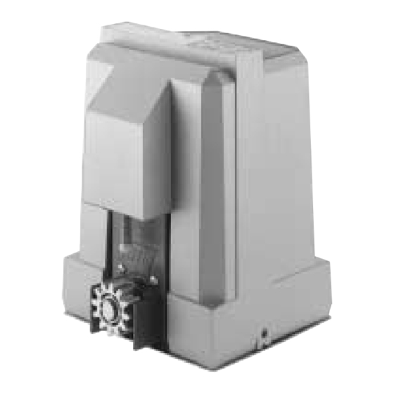
Operatore irreversibile per cancelli scorrevoli - Operateur irreversible pour portails coulissantes
Irreversible operator for sliding gates - Selbsthemmender Torantrieb für Schiebetüren
Mod.
Operatore
Operateur
Operator
Torantrieb
Operador
K5 CK
K5 CK
KIT K5 SC
SC => senza cremagliera - sans cremaillere - without rack - ohne zahnstange - sin cremallera
Operador irreversible para verjas correderas
K5 cK
Alimentazione
Peso max cancello
Alimentation
Poids maxi du portail
Power Supply
Max gate weight
Stromspannung
Max Torgewicht
Alimentación
Peso máx. verja
230V 50/60Hz
500Kg / 1100lbs
120V 60Hz
500Kg / 1100lbs
230V 50/60Hz
500Kg / 1100lbs
Spinta max
Poussée maxi
Max Thrust
Max Schubkraft
Empuje K
36Kg / 81lbs
36Kg / 81lbs
36Kg / 81lbs
AD00654
Pag. 1 di 44
I
F
GB
D
ES
Misure in mm
Mesures en mm
Measurements in mm
Abmessungen in mm
Medidas en mm/pulgadas
codice
code
code
code
código
AA33685
AA33686
Table des Matières

Manuels Connexes pour RIB K5 CK


Sommaire des Matières pour RIB K5 CK
- Page 1 INSTRUCIONES PARA EL USO Y LA INSTALACIÓN Operatore irreversibile per cancelli scorrevoli - Operateur irreversible pour portails coulissantes Irreversible operator for sliding gates - Selbsthemmender Torantrieb für Schiebetüren Operador irreversible para verjas correderas K5 cK Mod. Misure in mm Mesures en mm...
-
Page 2: Table Des Matières
Pag. 2 di 44 INDICE INDEX Caratteristiche Tecniche ..................pag.6 Caractéristiques techniques ..................pag.13 Controllo pre-installazione ..................pag.6 Contrôle pré-installation..................pag.13 Sblocco d’emergenza, Fissaggio motore e cremagliera..........pag.7 Déblocage d'urgence, Installation moteur et crémaillère........pag.14 Regolazione finecorsa, Manutenzione ..............pag.7 Réglage du fin de course, Entretien ..............pag.14 Collegamenti elettrici ...................pag.8-9 Branchements électriques ................pag.15-16 Controllo senso di rotazione del motore, Programmazione Tempi ......pag.10... - Page 3 à clé). 2° - Per la sezione ed il tipo dei cavi la RIB consiglia di utilizzare un cavo di tipo H05RN- 2° - En ce qui concerne la section et le type des câbles, le conseil de la RIB est celui...
-
Page 13: Caractéristiques Techniques
Pag. 13 di 44 SCHÉMA DÉTAILLÉ DE L'INSTALLATION Ç A - Operateur K5 B - Photocellules p/protec. externe C - Cremaillere D - Selecteur E - Antenne radio F - Signal electrique G - Camme en fin de course L - Cordon mécanique M - Cordon pneumatique Fig. -
Page 14: Manoeuvre De Secours
Pag. 14 di 44 MANOEUVRE DE SECOURS Effectuer seulement apres avoir coupé l'alimentation. Pour ouvrir manuellement le portail en cas de panne de courant, tourner la clé RIB dans Ç le sens horaire. Pour revenir à un fonctionnement electrique tourner-le en sens contraire (Fig. -
Page 15: Branchements Électriques
Pag. 15 di 44 BRANCHEMENTS ÉLECTRIQUES Ç SPARK ALIMENTATION BRANCHEMENT MOTEUR FIT SYNCRO BLOCK bouton-poussoir FLAT CORDON DE SÉCURITÉ... -
Page 16: B - Ajustez Les Microinterrupteurs De Controle
Pag. 16 di 44 Ç Cod. BC07056 K-CRX 230-50/60Hz Cod. BC07057 K-CRX 120-60Hz B - AJUSTEZ LES MICROINTERRUPTEURS DE CONTROLE A - BRANCHEMENTS J1=> NE TOUCHEZ PAS LE PONTET! MICROINTERRUPTEURS POUR PROCEDURES S'IL EST ENLEVÉ, L'OPÉRATEUR NE SE DÉPLACE PAS! DIP 1 CONTROLE DU SENS DE ROTATION DU MOTEUR (ON) (POINT C) DIP 2... -
Page 17: D - Programmation Des Temps
Pag. 17 di 44 Le ralentissement est déterminé automatiquement par la centrale en phase de E - PROCEDURE D’APPRENTISSAGE CODE RADIO programmation des temps, et est activé à environ 15-20 cm avant l’atteinte du fin de (UNIQUEMENT MODELES CRX) course d’ouverture ou de fermeture. 1 - La programmation peut être effectuée quelle que soit la position du portail. -
Page 18: Fonctionnements Des Accessoires De Sécurité
Pag. 18 di 44 ATTENTION: Si JP3 est fermé la fonction black out n'est pas active. Si JP3 est ouvert la fonction black out est active Ç Black out Au retour de l'alimentation secteur Si le portail est totalement fermé Il restera fermé... -
Page 19: Accessoires
Pag. 19 di 44 ACCESSOIRES FIT SYNCRO PLAQUE À CIMENTER code ACG8101 Ç PHOTOCELLULES MURALES FIT SYNCRO - code ACG8026 Portée cloisonnable 10÷20mt. Plusieurs couples sont appliqués, rapprochés les uns des autres grâce au circuit synchronisé. Ajouter le TRANSMETTEUR SYNCRO code ACG8028 s'il existe plus de deux couples de photocellules (jusqu'à... - Page 41 Pag. 41 di 44 REGISTRO DI MANUTENZIONE - DOSSIER D’ENTRETIEN MAINTENANCE LOG - WARTUNGSREGISTER - REGISTRO DE MANTENIMIENTO Il presente registro di manutenzione contiene i riferimenti tecnici e le registrazioni delle attività di installazione, manutenzione, riparazione e modifica svolte, e dovrà essere reso disponibile per eventuali ispezioni da parte di organismi autorizzati. Ce dossier d’entretien contient les références techniques et les enregistrements des opérations d’installation, d’entretien, de réparation et de modification effectuées, et devra être rendu disponible pour les inspections éventuelles de part d’orgenismes autorisée This maintenance log contains the technical references and records of installation works, maintenance, repairs and modifications, and must be made available for inspection purposes to authorised bodies.
-
Page 42: Declaración De Coformidad
We declare under our responsibility that K5 cK operator is conform to the following standards: Wir erklaeren das der K5 cK den folgenden EN-Normen entspricht: Declaramos bajo nuestra responsabilidad que los operators K5 cK es conforme a la siguientes normas y disposiciones: EN 301 489-1... - Page 43 Pag. 43 di 44 NOTE:...