RIB KIT PRINCE 24V Mode D'emploi
Masquer les pouces Voir aussi pour KIT PRINCE 24V:

Publicité

Les langues disponibles
  • FR

Les langues disponibles

Liens rapides

KIT PRINCE 24V
Brevettato - Patented
N. 1 503 019 - US 7,000,353 B2
Operatore
Alimentazione
Operateur
Operator
Power Supply
Torantrieb
Stromspannung
Operador
KIT PRINCE 24V
230V 50/60Hz
KIT PRINCE 24V Wi-Fi
ITALIANO pag. 05 / FRANÇAIS pag. 16 / ENGLISH page 27 / DEUTSCH pag. 37 / ESPAÑOL pag. 48
KIT PRINCE 24V
KIT PRINCE 24V Wi-Fi
Peso max anta
Alimentation
Poids maxi battant
Max leaf weight
Max. Torgewicht
Alimentacion
Peso max hoja
250 kg / 550 lbs
con / avec / with / mit
T2 PRINCE 24V
Spinta
Poussée
Thrust
Schubkraft
Empuje
100 kg / 220 lbs
1
Spinta max
Codice
Poussée maxi
Max thrust
Max Schubkraft
Empuje max.
Codigo
AD00732
140 kg / 309 lbs
AD00734
Code
Code
Code

Publicité

Table des Matières
loading

Sommaire des Matières pour RIB KIT PRINCE 24V

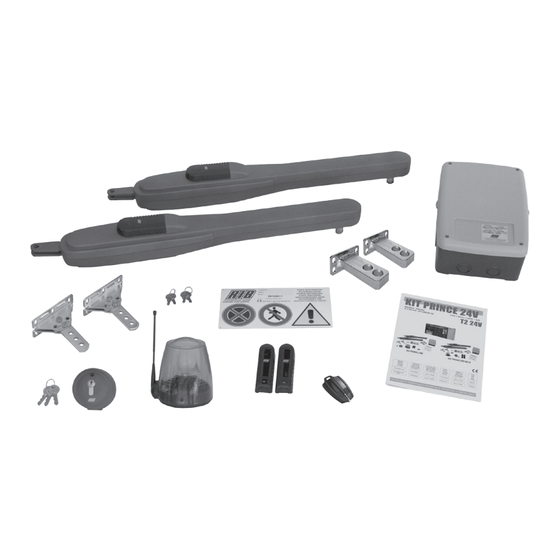
  • Page 1 KIT PRINCE 24V con / avec / with / mit Brevettato - Patented N. 1 503 019 - US 7,000,353 B2 T2 PRINCE 24V KIT PRINCE 24V KIT PRINCE 24V Wi-Fi Operatore Alimentazione Peso max anta Spinta Spinta max Codice...
  • Page 2: La Ditta Rib Non Accetta Nessuna Responsabilità Per Eventuali

    à clé). 2° - Per la sezione ed il tipo dei cavi la RIB consiglia di utilizzare un cavo di tipo 2° - En ce qui concerne la section et le type des câbles, RIB conseille d’utiliser un câble...
  • Page 3 (z.B.mit einen Schluesselkatsten in einem Panzergehaeuse). 2° - For the section and the type of the cables RIB advices to use a cable of H05RN-F 2° - RIB empfiehlt den Kabeltyp H05RN-F mit einem minimalen Querschnitt von 1,5 mm...
  • Page 4 (por ejemplo instalándolo dentro de un panel cerrado a llave). 2° - Para la sección y el tipo de los cables, RIB aconseja utilizar cables de tipo H05RN-F con sección mínima de 1,5 mm 2 e igualmente atenerse a la norma IEC 364 y a las normas de instalación del propio país.
  • Page 5 LAYOUT IMPIANTO CARATTERISTICHE TECNICHE PRINCE è un’operatore in grado di movimentare cancelli a battente con ante lunghe fino a 3 m e pesanti fino a 250 kg (Fig. 1). PRINCE è stato concepito per lavorare senza finecorsa elettrici, ma solo meccanici.
  • Page 6 INSTALLAZIONE PRINCE CONTROLLO PRE-INSTALLAZIONE Le ante devono essere solidamente fissate ai cardini delle colonne, non devono flettere durante il movimento e devono muoversi senza attriti. Prima d’installare PRINCE è meglio verificare tutti gli ingombri necessari per poterlo installare. Se il cancello si presenta come da Fig. 1 non occorrono modifiche. È...
  • Page 7 Rispettare la misura e assicurarsi che l’operatore sia orizzontale Attacco colonna Misure da rispettare per una corretta installazione Min.÷Max Attacco anta 13,5 S2-X S2-Y 13,5 13,5 S3-X S3-Y S3-X 90° S3-X 1÷3 19,5 S3-X 21,5 S1-Z S1-Z Qualora il pilastro fosse molto largo e non fosse possibile installare l’elettroriduttore rispettando la misura (B), è...
  • Page 8: Collegamenti Elettrici

    FERMO MECCANICO - OPTIONAL (Cod. ACG8088) Fermo meccanico OPTIONAL per fermare la chiusura in caso il cancello sia privo di un fermo a terra. REGOLAZIONE FINECORSA MECCANICI Per posizionare i fermi si deve agire come da schema (Fig. 11). Per ottenere l’apertura desiderata è sufficiente spostare il fermo (A) e bloccarlo serrando la vite da 8mA con una chiave fissa n°13.
  • Page 9 T2 PRINCE 24V cod. AC02029 T2 PRINCE 24V-CRX cod. AC02030 24Vdc 0,8A ± 15% per ACCESSORI LAMPEGGIATORE 24Vdc 0,8A ± 15% per AUTOTEST COSTE 24Vdc 20W PEDONALE SERRATURA PASSO PASSO ALIMENTAZIONE ELETTRICA 230Vac 50Hz FOTOCELLULE FUSE COMUNE T 2 A COSTE TRASFORMATORE R=2,2K 1/4W...
  • Page 10 CRX). NON TOCCARE IL PONTICELLO! SE VIENE RIMOSSO L’OPERATORE NON FUNZIONA! SW RADIO RADIO Modulo radio incorporato (modello CRX), o connettore per radio ricevitore RIB ad innesto con alimentazione a 24Vdc BATTERY Connettore per scheda di ricarica batteria a 24Vdc (cod. CHARGER ACG4648) TRIMMER RUN Trimmer di regolazione dell’alta velocità...
  • Page 11 REGOLAZIONI 4 - Raggiunto il fermo meccanico di apertura, il SENSORE DI CORRENTE AUTOMATICO ferma M1 (con memorizzazione del tempo e della corrente)=> Nello stesso momento si attiva M2 che apre. ATTENZIONE: ABILITARE IL DIP 3 SOLO DOPO AVER ESEGUITO TUTTE LE 5 - Raggiunto il fermo meccanico di apertura, il SENSORE DI CORRENTE AUTOMATICO ferma PROGRAMMAZIONI.
  • Page 12 Da questo momento le sicurezze o altri comandi del cancello funzioneranno normalmente 6 - Riposizionare DIP 1 su OFF e DIP 3 su OFF. (inversioni, stop, allarmi, ecc..). NOTA: SE IL LED DL1 CONTINUA A LAMPEGGIARE VELOCEMENTE, SIGNIFICA CHE IL DIP 1 RISULTA ANCORA POSIZIONATO IN ON E QUALSIASI MANOVRA VIENE 6 - Finito il conteggio del tempo il cancello si ferma.
  • Page 13 ecc. EDGE (COSTA) (COM-EDGE) Se DIP 6 su ON => Esegue l’apertura a cancello chiuso. Se azionato durante il movimento Durante l’apertura, se impegnata, inverte il moto in chiusura. di apertura non ha effetto. Se azionato con cancello aperto, lo chiude. Se azionato durante il Durante la chiusura, se impegnata, inverte il moto in apertura.
  • Page 14: Caratteristiche Tecniche

    FUNZIONE PRE-LAMPEGGIO - Carico massimo lampeggiatore 24Vdc 20W DIP 5 - OFF => il motore e il lampeggiatore partono contemporaneamente. - Corrente disponibile per fotocellule e accessori 1A ±15% DIP 5 - ON => il lampeggiatore parte 3 secondi prima del motore. - Corrente disponibile su connettore radio 200mA SPIA DI SEGNALAZIONE CANCELLO APERTO (COM-SIGNAL) CARATTERISTICHE TECNICHE RADIO (modello T2 PRINCE 24V crx)
  • Page 15 OPTIONAL - Per i collegamenti ed i dati tecnici degli accessori attenersi ai relativi libretti di istruzione. BATTERIA SCHEDA DI CARICA BATTERIA Batteria 2,2Ah 12V cod. ACG9515 cod. ACG4648 SERRATURA ELETTRICA CHIAVISTELLO MECCANICO Serratura Orizzontale - destra vista esterna - 12Vac cod.
  • Page 16: Schéma Détaillé De L'installation

    SCHÉMA DÉTAILLÉ DE L’INSTALLATION CARACTERISTIQUES TECHNIQUES PRINCE est un opérateur utilisé pour manoeuvrer des portails à battans jusqu’à 3 m de longeur et 250 kg de poids (Fig.1). Les opérateurs PRINCE utilisent les fin de course mécaniques intégrés, de ce fait évitant le devoir installer des fins de course électriques.
  • Page 17 INSTALLATION PRINCE CONTROLE PRE-INSTALLATION Le portail à battant doit être solidement fixé aux poteaux, ne doit pas flechir pendant le mouvement et doit pouvoir manoeuvrer sans effort. Avant d’installer PRINCE, il convient de verifier tous les encombrements necessaires pour proceder à l’installation. Si le portail se presente comme indiqué...
  • Page 18 Se conformer à la mesure et faire en sorte que l’opérateur est horizontale Attache poteau Mesures à respecter pour une correcte installation Min.÷Max Attache vantail 13,5 S2-X S2-Y 13,5 13,5 S3-X S3-Y S3-X 90° S3-X 1÷3 19,5 S3-X 21,5 S1-Z S1-Z Si le pilier est très large et qu’il n’est pas possible d’installer le motoréducteur en respectant la mesure (B), il faut realiser une niche...
  • Page 19: Arrêt Mécanique - Option

    ARRÊT MÉCANIQUE - OPTION (Cod. ACG8088) Arrêt mécanique en OPTION pour arrêter la fermeture si le portail n’est pas pourvu de dispositif d’arrêt au sol. REGLAGE FINS DE COURSE MECANIQUES Pour positionner les colliers, il est necessaire agir selon les indications du schema (Fig. 11). Pour obtenir l’ouverture desirée, il suffit de déplacer le collier (A) et de le bloquer en vissant la vis M8 avec une clé...
  • Page 20 T2 PRINCE 24V code AC02029 T2 PRINCE 24V-CRX code AC02030 24Vdc 0,8A ± 15% pour ACCESSOIRES 24Vdc 0,8A ± 15% AUTOTEST pour FEU CLIGNOTANT BARRE PALPEUSE 24Vdc 20W PIETON SERRURE PAS A PAS ALIMENTATION ÉLECTRIQUE 230Vac 50Hz PHOTOCELLULES Fusible COMMUN T 2 A BARRE PALPEUSE TRANSFORMATEUR...
  • Page 21 LE SYSTÈME RADIO EST ENLEVÉ, IL NE FONCTIONNE PAS! SW RADIO RADIO Module radio incorporé (modèle CRX), ou connecteur pour radio récepteur RIB à enclenchement avec alimentation à 24Vdc BATTERY Connecteur pour fiche de recharge batterie à 24Vdc (code CHARGER...
  • Page 22: C - Contrôle Du Sens De Rotation Du/Des Moteur/S

    PROG => S3 Bouton pour la programmation D - PROGRAMMATION DES TEMPS POUR 2 MOTEURS (#) AVEC DETECTEUR REGLAGES DE COURANT ACTIVE (DIP 7 ON) PENDANT LA PROGRAMMATION LE DETECTEUR DE COURANT EST TOUJOURS ACTIF. ATTENTION: POSITIONNER LE DIP 3 SUR ON SEULEMENT APRES AVOIR EFFECTUE 1 - Le portail doit être totalement fermé.
  • Page 23: Signalisation Memoire Saturee Codes Radio Reserves A L'ouverture Pietonne

    1 - Le portail doit être totalement fermé. 1 - Positionner DIP 1 sur ON et ensuite DIP 3 sur ON. 2 - Mettez le micro-interrupteur DIP 2 sur ON => la DEL DL1 émettra des clignotements 2 - La DEL rouge DL1 de programmation clignote avec une fréquence de 1 sec. ON et 1 sec. brefs.
  • Page 24: Fonctionnement Des Accessoires De Securite

    Demander T2 PRINCE 24V avec fw 04 NOUP. En connectant un interrupteur et/ou une protéger les photocellules de sources de dérangement. Faire attention de ne pas provoquer de court-circuit quand les phases d’alimentation horloge de type quotidien/hebdomadaire (à la place ou en parallèle du poussoir d’ouverture N.O.
  • Page 25: Caracteristiques Tecniques

    CARACTERISTIQUES TECNIQUES bouton de commande. - Intervalle de température 0 ÷ 55°C TRAVAIL AVEC HOMME PRESENT, DANS LE CAS DE PANNE DE SÉCURITÉ - Humidité < 95% sans condensation Si le barre palpeuse est en panne ou engagé pour plus de 5 secondes, ou si la cellule - Tension d’alimentation 230V~ ±...
  • Page 26 DEFAUT SOLUTION Après avoir effectué les différents raccordements et avoir allumé le courant, Vérifier l’intégrité des fusibles F1, FUSE 1. toutes les leds sont éteintes. En cas de fusible hors service, ne remplacer qu’avec des fusibles de valeur adéquate F1 T 2A FUSIBLE DE PROTECTION TRANSFORMATEUR (extérieur à...
  • Page 27: System Lay-Out

    SYSTEM LAY-OUT TECHNICAL FEATURES PRINCE 24V is a linear operator designed for swing gates long up to 3 m and weight up to 250 kg (Pic. 1). PRINCE 24V works without electric limit switches, but with mechanical stoppers. N.B.: It is advisable to fit an electrical lock to ensure an efficient gate locking.
  • Page 28: Pre-Installation Check List

    INSTALLATION PRINCE PRE-INSTALLATION CHECK LIST The gate leaves must be firmly fixed to the hinges on the gate pillars, they must not flex during the movement and they must swing without any friction. Before installing the operator, make sure you have enough room to fix the operator on the pillar. In case the gate is like the one depicted in Pic.
  • Page 29 Comply with the measure and make sure that the operator is horizontal In order to carry out a proper installation of the operator, it is necessary to comply with the geometry measurement shown in the tables below. Column attachment Respect the measures for a correct installation Min.÷Max Leaf attachment 13,5...
  • Page 30: Electric Connections

    MECHANICAL STOPPER - OPTIONAL (Code ACG8088) Optional mechanical stopper to stop the closing, if the gate is not fitted with a floor stopper. MECHANICAL STOPPER ADJUSTMENT To adjust the stoppers you have to follow the scheme (Pic. 11). To set the opening limit it is enough to fix the stopper (A) in the needed position by tightening the 8mA screw with a n.
  • Page 31 T2 PRINCE 24V code AC02029 T2 PRINCE 24V-CRX code AC02030 24Vdc 0,8A ± 15% for ACCESSORY SUPPLY BLINKER 24Vdc 0,8A ± 15% for AUTOTEST SAFETY STRIPS 24Vdc 20W PEDESTRIAN ELECTRIC STEP BY STEP POWER SUPPLY LOCK 230Vac 50 Hz PHOTOCELLS FUSE COMMON T 2 A...
  • Page 32 CRX control board) DO NOT REMOVE ANY JUMPER! OTHERWISE THE OPERATOR WILL NOT WORK! SW RADIO RADIO Built-in radio module (model CRX), or connector for radio receiver RIB, 24 Vdc supply BATTERY CHARGER Connector for charge card of 24Vdc battery (code ACG4648) TRIMMER RUN...
  • Page 33 D - SETTING THE TIME FOR ONE MOTOR (M1) (#) WITH POWER SENSOR IF COMPLIANCE WITH THE AFOREMENTIONED STANDARD IS UNNECESSARY, SIMPLY POSITION DIP 3 TO OFF. IN THIS CASE THE GATES STOP WITHOUT REVERSING. ACTIVATED (DIP 7 ON) CAUTION: FOR ONE MOTOR CONTROL DIP 13 MUST BE POSITIONED TO ON; DURING RUN TRIMMER (TR1) high-speed electronic regulator PROGRAMMING THE POWER SENSOR IS CONTINUOUSLY ACTIVE.
  • Page 34 remote is memorized properly LED DL10 (green) blinks. the gate reopens. OPEN BUTTON (COM-OPEN) 4 - The programming time for codes is automatically renewed in order to memorize the next remote control. The button controls the opening movement when the gate is stationary. If activated while 5 - To finish programming, wait 10 seconds, or press the PROG button briefly.
  • Page 35: Technical Specifications

    shield the photocells from external noise. in progress. Be careful not to short circuit the system when the supply phases are inverted! Note 2: the stop command is not to be considered a safety command that can be bypassed in this mode. Therefore, when pressed or damaged, it will not allow any movement CONTROL OF IMMEDIATE CLOSING AFTER MOVEMENT IN FRONT OF PHOTOCELLS of the gate.
  • Page 36: Accessories

    TROUBLE SHOOTING After having carried out all connections, by carefully following the layout and having positioned the gate in intermediate position, check the correct ignition of red LEDS DL7, DL8 and DL9 In case of no ignition of the LEDS, always with gate in intermediate position, check the following and replace any faulty components. DL7 switched OFF Faulty photocells DL8 switched OFF Faulty safety edge (In case the edge is not connected, carry out jumper between COM and EDGE) DL9 switched OFF Stop button malfunction (if Stop is not connected, perform the jump between COM and STOP).
  • Page 37: Technische Eigenschaften

    ANLAGEN LAY-OUT TECHNISCHE EIGENSCHAFTEN PRINCE ist eine Antriebe die für Drehtore mit den Torflügen bis zu 3 m und 250 kg verwendbar sind (Abb. 1). PRINCE benutzen eingebaute mechanische Stopper und so ist es nicht Notwendig einen elekrtrischen Endschalter zu installieren. NOTIZ: Wenn Sie einen Prince installieren empfehlen wir ihnen ein elektrisches Schloss zur sicheren Verrieglung zu installieren.
  • Page 38 INSTALLATION PRINCE PRÜFUNG VON DER MONTAGE Das Flugeltor muß fest an der Angelpunkten der Träger fixiert sein, darf sich während der Bewegung nicht biegen und ohne Reibung bewegen. Bevor PRINCE montiert wird ist es besser alle Hindernisse, die bei der Montage auftreten können festzustellen.
  • Page 39 Beachten Sie die Maßnahme und stellen Sie sicher, dass der Betreiber ist horizontal Halterung Pfeiler Die korrekten Abmessungen und Installation mit einem Stopper im Antrieb Min.÷Max Halterung Torfluegel 13,5 S2-X S2-Y 13,5 13,5 S3-X S3-Y S3-X 90° S3-X 1÷3 19,5 S3-X 21,5 S1-Z...
  • Page 40 ECHANISCHE SPERRVORRICHTUNG - OPTIONEN (Kode ACG8088) Als Zubehör eine mechanische Sperrvorrichtung, die das Gittertor beim Schließen anhält, falls keine Feststellvorrichtung auf dem Boden vorhanden ist. INSTELLUNG DES MECHANISCHEN ENDSCHALTERS Um die Endschalter einzustellen, müssen Sie wie in der Abbildung handeln (Abb. 11). Um die erwünschte Offnungsweite einzustellen, genüngt es, die Endschalter (A) zu verstellen und sie mit Hilfe eines Imbusschlüßels an der Mutterschraube festzuziehen.
  • Page 41 T2 PRINCE 24V Kode AC02029 T2 PRINCE 24V-CRX Kode AC02030 24Vdc 0,8A ± 15% für ZUBEHÖRE BLINKER 24Vdc 0,8A ± 15% für AUTOTEST KONTAKTLEISTE 24Vdc 20W FUSSGÄNGER EINZELIMPULS STROMVERSORGUNG ELEKTROSCHLOSS 230Vac 50 Hz FOTOZELLEN SICHERUNG GEMEINSAME ERDUNGSKONTAKTE T 2 A KONTAKLEISTE TRANSFORMATOR R=2,2K 1/4W...
  • Page 42 Verbinder für die Programmierung in der Fabrik (nur für die Modelle CRX). NICHT DIE ÜBERBRÜCKUNG BERÜHREN ! OHNE ANTRIEB NICHT BETRIEBSFÄHIG! SW RADIO RADIO Radio-Modul eingebaut (Modell CRX), oder Verbinder für Radioempfänger RIB Steckverbindung mit Speisung zu 24Vdc BATTERY Verbinder für Batterie-Aufladekarte zu 24Vdc (Kode CHARGER ACG4648) TRIMMER RUN Trimmer elektronischer Regler für hohe Geschwindigkeit...
  • Page 43 EINSTELLUNGEN 1 - Das Tor muss vollständig geschlossen sein. 2 - DIP 2 auf ON stellen=> Die LED-AnzeigeDL1 beginnt zu blinken. ACHTUNG: AKTIVIEREN DAS DIP 3 NÜR NACH ALLE DIE PROGRAMMIERUNGEN. 3 - Den Schalter PROG. drücken=> M1 öffnet. ZU BEACHTEN: MIT DIP 3 (ON) WIRD DIE FUNKTION DER KURZFRISTIGEN FLÜGELUMKEHR NACH DEM ANSCHLAG AKTIVIERT.
  • Page 44 Alarmfunktionen, usw..). Fernbedienung programmiert werden kann. 6 - Nach der Zeitbestimmung schließt das Tor. 5 - Um die Programmierung abzuschließen, 10 Sekunden abwarten oder die Taste PROG 7 - NACH BEENDIGUNG DER PROGRAMMIERUNG DIP 2 AUF OFF STELLEN. drücken. Die rote LED-Anzeige erlischt. 6 - Erneut DIP 1 und DIP 2 auf OFF stellen.
  • Page 45 Öffnung, hält das Tor an und schließt sich SCHLIESSUNGS-TASTE (COM-CLOSE) nach nur 1 Sekunde nach Freigabe der Führt bei stillstehendem offenem Tor zur Schließung. Fotozellen Steht DIP 16 auf ON und DIP 4 auf ON => aktivieren sich die Fotozellen während der FERNSTEUERUNG Öffnung, so öffnet sich das Tor weiter.
  • Page 46: Lösung Von Problemen

    TECHNISCHE EIGENSCHAFTEN beliebigen Befehlstaste möglich. - Temperaturbereich 0 ÷ 55°C ARBEIT IM MANNSBEISEIN IM FALL EINES AUSFALLS DER SICHERHEITEN - Feuchtigkeit < 95% ohne Kondensierung Wenn die Kontaktleiste ist defekt oder diese arbeit länger als 5 Sekunden, oder wenn - Versorgungsspannung 230V~ ±10% (120V/60Hz auf Anfrage) die Fotozelle defekt ist oder für mehr als 60 Sekunden arbeit, die Befehle ÖFFNEN, - Frequenz...
  • Page 47 FEHLER LÖSUNG Nachdem die verschiedenen Verbindungen gelegt sind und Strom angelegt wurde, Die Unversehrtheit der Sicherungen F1, FUSE 1 überprüfen. sind alle LEDs ausgeschaltet. Die Sicherungen mit geleichwerteigen ersetzen. F1 T 2A SICHERUNG ZUM TRANSFORMATORSCHUTZ (außerhalb des Steckverbinders T2 PRINCE 24V) FUSE 1 8A SICHERUNG ZUM MOTORSCHUTZ Der Motor öffnet und schließt, aber hat keine Antriebskraft und bewegt sich langsam.
  • Page 48: Características Técnicas

    DISPOSICIÒN DE LA INSTALACIÒN CARACTERÍSTICAS TÉCNICAS PRINCE es un operador capaz de desplazar cancelas con batientes de hojas largas hasta 3 m y pesadas hasta 250 kg (Fig. 1). PRINCE ha sido concebido para trabajar sin finales de carrera eléctricos, sino sólo mecánicos.
  • Page 49 INSTALACIÓN PRINCE CONTROLES DE LA PRE-INSTALACIÓN La puerta de batiente debe fijarse sólidamente a las bisagras de las columnas y no debe balancearse durante el movimiento. Antes de proceder a la instalación de PRINCE, es prudente verificar todos los espacios necesarios para emplazarlo.
  • Page 50 Cumplir con la medida y asegurarse de que el operador esté en posición horizontal Enganche columna Medidas a respetar para una instalación correcta Min.÷Max Enganche cancela 13,5 S2-X S2-Y 13,5 13,5 S3-X S3-Y S3-X 90° S3-X 1÷3 19,5 S3-X 21,5 S1-Z S1-Z En el caso de que el pilar fuera demasiado ancho y no fuese posible...
  • Page 51: Conexiones Eléctricas

    SEGURO MECÁNICO - OPTIONAL Seguro mecánico opcional para detener el cierre en el caso de que la cancela no esté provisto de una seguro de tierra. AJUSTE DE LOS FINALES DE CORRIDA MECÁNICOS Para posicionar los seguros se debe actuar según el esquema (Fig. 11). Para obtener la abertura deseada es suficiente mover el seguro (A) y boquearlo serrando la vite da 8mA con la llave fija n°...
  • Page 52 T2 PRINCE 24V cód. AC02029 T2 PRINCE 24V-CRX cód. AC02030 24Vdc 0,8A ± 15% para ACCESSORIOS INTERMITENTE 24Vdc 0,8A ± 15% para AUTOTEST COSTAS 24Vdc 20W PEATONAL CERRADURA PASSO PASSO ALIMENTACION ELÉCTRICA 230Vac 50Hz FOTOCÉLULAS FUSIBLE COMÚN T 2 A COSTAS TRANSFORMADOR R=2,2K 1/4W...
  • Page 53 REMOVIDO EL SISTEMA DE RADIO NO FUNCIONA! SW RADIO RADIO Módulo radio incorporado (modelo CRX), o conector para radio receptor RIB con engranaje con alimentación de 24Vdc BATTERY Conector para tarjeta para la recarga de batería de 24Vdc CHARGER (cód. ACG4648)
  • Page 54 REGULACIONES NOTA: Durante este control el stop, las fotocélulas y las costas no están activas. D - PROGRAMACIÓN DE LOS TIEMPOS PARA 2 MOTORES (#) CON SENSOR DE ATENCIÓN: PONER EL DIP 3 EN ON, SOLO DESPUÉS DE HABER TERMINADO TODAS LAS PROGRAMACIÓNES.
  • Page 55: Funcionamiento Accesorios De Mando

    FUNCIONAMIENTO POR TIEMPO (DIP 7 OFF) 4 - Vuelva a colocar el DIP 1 en posición OFF y el DIP2 en OFF 5 - Final del procedimiento. ATENCIÓN: PARA GESTIONAR UN SOLO MOTOR, EL DIP 13 DEBE ESTAR COLOCADO EN POSICIÓN ON. F - PROGRAMACIÓN DE LOS CÓDIGOS DE RADIO DE APERTURA PEATONAL 1 - La cancela debe estar completamente cerrada.
  • Page 56 24Vdc Cont. soporte a los contactos A- para proteger las fotocelulas contas las interferencias. La Función Reloj es útil durante las horas pico, cuando el tráfico vehicular es lento (por Poner atención a no causar cortos circuitos cuando las ej. entrada/salida de trabajadores, emergencias en zonas residenciales o zonas de aparcamientos y, temporalmente, por mudanzas).
  • Page 57: Resolución De Problemas

    El estado de alarma será visualizado por el intermitente que permanecerá activo durante primer comando recibido serà el de cierre. El cierre de las dos hojas se hará con el desfase 1 minuto. Durante este tiempo es posible restablecer el funcionamiento de la cancela total entre las dos hoja, y por lo tanto, primero serà...
  • Page 58 DEFECTO SOLUCIÓN Después de haber efectuado varias conexiones y haber dado tensión, Verifique la integridad de los fusibles F1, FUSE 1 todos los led están apagados. En caso de fusible interrumpido, utilice únicamente uno de valor adecuado. F1 T 2A FUSIBLE DE PROTECCIÓN TRANSFORMADOR (externo a la tarjeta T2 PRINCE 24V) FUSE 1 8A FUSIBLE DE PROTECCIÓN DE MOTORES El motor abre y cierra, pero no tiene fuerza y se mueve lentamente.
  • Page 59 KIT PRINCE 24V ACG1083 CCA1263 BA01046 CME5235 CAL1158 CRS6204R CCA1351 CPL1163 DRL10X30I CME2125 CPL1164 CTC1269 DTE10X20I CTC1116 BA01076 CME9056 CVA1176 CTC1253 CPL1165 DAC4X14 CMO1286 DTM10X40I CME6085 CPL1127 DRD4 DTB55X40 DRL10X20I DDD10MAI ACG8088 CAL1157 CPL1167 DAC29X95 CEL1457 Codice Denominazione Particolare CME9056...
  • Page 60 Dichiarazione di incorporazione per le quasi-macchine - Direttiva Macchine 2006/42/CE, Allegato II., B Déclaration d’incorporation pour les quasi-machines - Directive Machines 2006/42/CE, Annexe II, B Declaration of incorporation for partly completed machinery - Machinery Directive 2006/42/EC, Annex II., B Einbauerklärung für unvollständige Maschinen - Maschinenrichtlinie 2006/42/EG, Anhang II, B Declaración de incorporación de una cuasi máquina - Directiva de Máquinas 2006/42/CE, Anexo II, B R.I.B.

Ce manuel est également adapté pour:

Kit prince 24v wi-fiAd00732Ad00734

Table des Matières