Table des Matières
Publicité
Les langues disponibles
Les langues disponibles
Liens rapides
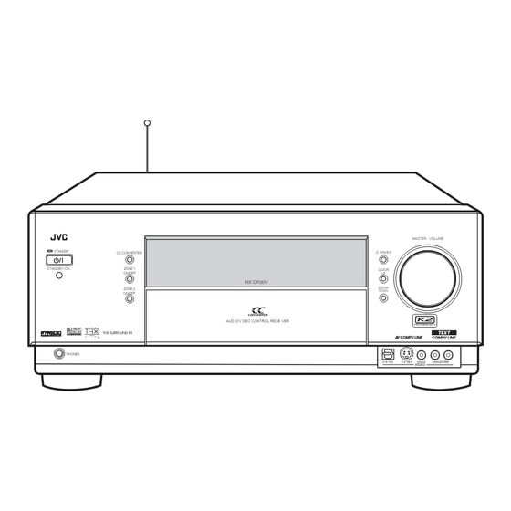
AUDIO/VIDEO CONTROL RECEIVER
RECEPTEUR DE COMMANDE AUDIO/VIDEO
RX-DP20VBK
STANDBY
CC CONVERTER
STANDBY/ON
ZONE 1
ON/OFF
ZONE 2
ON/OFF
PHONES
MASTER VOLUME
DIMMER
DOOR
UP
RX-DP20V
DOOR
DOWN
AUDIO/VIDEO CONTROL RECEIVER
DIGITAL
S-VIDEO
VIDEO
VIDEO
INSTRUCTIONS
MANUEL D'INSTRUCTIONS
LEARN
TRANSMIT
STANDBY
ON
ZONE 1
ZONE 2
ZONE 1
ZONE 2
TV/CATV/DBS
VCR 1
ON/OFF
ON/OFF
STANDBY/ON
STANDBY/ON
ZONE 1
ZONE 2
LEARN
DVD
DVD MULTI
PHONO
CD
VCR 1
VCR 2
TAPE/MD
CDR
TV/DBS
VIDEO
FM/AM
EXT 7.1CH
ANALOG/DIGITAL
EFFECT
1
2
3
INPUT
LIVENESS
SOUND
4
5
6
TEST
7
8
9
/P
CC CONVERTER
10
0
+
10
RETURN
FM MODE
100 +
THX
SURROUND
DSP
SURR/DSP
OFF
EX/ES/7.1
ANALOG DIRECT
SLEEP
DIMMER
TV
CATV/
DBS
/ REW
PLAY
FF/
DOWN
TUNING
UP
REC
STOP
PAUSE
TV/VIDEO
TV VOL
CHANNEL
VOLUME
MUTING
SETUP
ADJUST
MENU
MENU
TEXT
SET
DISPLAY
DVD
EXIT
MENU
LIGHT
L—AUDIO—R
RM-SRXDP20J
REMOTE CONTROL
A/V CONTROL RECEIVER
For Customer Use:
Enter below the Model No. and Serial
No. which are located either on the rear,
bottom or side of the cabinet. Retain this
information for future reference.
Model No.
Serial No.
LVT0965-002B
[C]
Publicité
Chapitres
Table des Matières
Dépannage

Manuels Connexes pour JVC RX-DP20VBK


Sommaire des Matières pour JVC RX-DP20VBK
-
Page 88: Caractéristiques
Convertisseur audio NA 192 kHz/24 bits PEM DD autre bande (BAND 1 ou BAND 2)—référez-vous à page 17 pour Le convertisseur exclusif de JVC a été mis à niveau pour être plus de détails. complètement compatible avec les spécifications élevées des DVD Si le problème persiste, arrêtez d’utiliser l’antenne-tige RF et la... - Page 89 Sélection du mode de réception FM ......... 34 AV COMPU LINK ........68 Réglages de base ........35 Commande des appareils audio/vidéo JVC ..71 Menu de réglage ............... 35 Commande à l’aide des affichages sur l’écran ......36 Commande des appareils audio ..........71 Procédure d’utilisation des menus ...........
-
Page 90: Identification Des Parties
Identification des parties Panneau avant INPUT MODE SURR/DSP DOWN SPEAKERS 1 SURROUND ADJUST MENU / TUNING ∞ / TUNING 5 / INPUT ATT / MEMORY SPEAKERS 2 ZONE 2 LEFT RIGHT EXIT ANALOG EX/ES/7.1 SETUP MENU / PRESET ∞ / PRESET 5 / ZONE 2 CONTROL / FM MODE... - Page 91 Référez-vous aux pages entre parenthèses pour plus de détails. Panneau avant Fenêtre d’affichage 1 Touche SPEAKERS 1 (20, 25) 1 Indicateur DUAL (24) 2 Touche INPUT MODE (25) • S’allume quand un signal Dual Mono est détecté. 2 Indicateur ANALOG (26) Touche INPUT ATT (26) •...
-
Page 92: Panneau Arrière
Panneau arrière 8 9 p q COMPU TEXT CTRL RF REMOTE ANTENNA AUDIO VIDEO AUDIO RIGHT LEFT LINK-4 COMPU COMPU COMPONENT LINK +12V (SYNCHRO) LINK- RIGHT LEFT VIDEO S-VIDEO ANTENNA RIGHT LEFT DIGITAL IN FRONT TV SOUND 10mA MAX PHONO 1 (DVD) CENTER BAND1... -
Page 93: Télécommande
7 Touche SOUND (39, 50, 56, 59, 71) Télécommande 8 Touche TEST (39, 71) 9 Touche CC CONVERTER (27, 71) p Touche THX (57, 71) LEARN TRANSMIT q Touche SURROUND (56, 57, 71) STANDBY w Touche EX/ES/7.1 (55, 71) ZONE 2 ZONE 1 ZONE 1 ZONE 2... -
Page 94: Pour Commencer
Pour commencer Cette section explique comment connecter les appareils audio/vidéo et les enceintes à l’ampli-tuner, ainsi que comment connecter l’alimentation. Connexion des antennes FM et AM Avant l’installation Général • Assurez-vous d’avoir les mains sèches. • Mettez tous les appareils hors tension. •... -
Page 95: Connexion De L'antenne Am
Connexion de l’antenne AM Connexion des enceintes Pour profiter pleinement des modes THX (voir page 51), il est recommandé d’utiliser des enceintes certifiées THX. Vous pouvez connecter les enceintes suivantes: • Deux paires d’enceintes avant pour produire le son stéréo normal. •... - Page 96 IMPORTANT: Après avoir connecté les enceintes, réglez l’information des enceintes correctement: Enceintes avant 1 • Pour obtenir le meilleur effet Surround/THX/DSP possible dans Enceinte centrale Droite / Gauche la Zone 1, référez-vous à “Réglages de base” aux pages 35 à 44. •...
-
Page 97: Amélioration De Votre Système Audio
À propos des prises FRONT 2/ZONE 2 SPEAKERS Amélioration de votre système audio Les prises FRONT 2/ZONE 2 SPEAKERS peuvent être utilisées de Vous pouvez utiliser cet ampli-tuner comme un préamplificateur la façon suivante: (amplificateur de commande) quand vous connectez des •... -
Page 98: Connexion Des Appareils Audio/Vidéo
Lecteur CD Connexion des appareils audio/vidéo AUDIO RIGHT LEFT Lors de la connexion d’appareils séparés, référez-vous aussi aux modes d’emploi que les accompagnent. PHONO Lecteur CD Connexions analogiques Connexions des appareils audio Utilisez des câbles munis de fiches cinch (non fournis). •... - Page 99 IMPORTANT: Appareil extérieur à 7,1 canaux Cet ampli-tuner est muni des prises vidéo suivantes—prises vidéo composites, S-vidéo et composantes vidéo. Vous pouvez utiliser n’importe lesquelles pour connecter un appareil vidéo. Cependant, respectez les points suivants pour la connexion: Décodeur • Les signaux vidéo composites et les signaux S-vidéo peuvent (ou lecteur de DVD) être convertis mutuellement, et peuvent aussi être convertis en signaux en composantes vidéo.
- Page 100 Vue arrière Magnétoscope(s) Magnétoscope D-VHS/S-VHS/VHS Å À l’entrée audio ı À la sortie audio Ç À la sortie en composantes vidéo Î À la sortie S-vidéo ‰ À la sortie vidéo composite Ï À l’entrée S-vidéo Ì À l’entrée vidéo composite VIDEO AUDIO COMPONENT...
- Page 101 Vue arrière Téléviseur et/ou tuner DBS VIDEO AUDIO COMPONENT RIGHT LEFT VIDEO S-VIDEO TV SOUND Lors de la connexion du téléviseur aux prises AUDIO (TV SOUND/DBS IN), NE CONNECTEZ PAS la sortie vidéo du (REC) téléviseur à ces prises d’entrée vidéo. 1 IN VCR 1 (DVD)
- Page 102 Lecteur de DVD • Lors de la connexion d’un lecteur de DVD avec les prises de sortie stéréo: VIDEO COMPONENT Vue arrière S-VIDEO Å À la sortie audio du canal avant gauche/droit (ou à la sortie audio mixée si nécessaire) ı...
-
Page 103: Connexions Numériques
Remarques: Connexions numériques • À l’expédition de l’usine, les prises DIGITAL IN ont été réglées pour Cet ampli-tuner est muni de six prises numériques d’entrée les appareils suivants. DIGITAL IN—trois prises numériques coaxiales et trois prises – 1 (coaxiale) : Pour le lecteur de DVD numériques optiques—et d’une prise de sortie numérique DIGITAL –... -
Page 104: Utilisation De L'antenne-Tige Rf Et De L'émetteur De Signaux Ir
(Dans le compartiment à piles) Si le problème persiste, arrêtez d’utiliser l’antenne-tige RF et la Vue arrière télécommande et consultez votre revendeur JVC ou le centre de service JVC le plus proche. La télécommande fournie avec cet ampli-tuner peut émettre à la fois Installation de l’émetteur de signaux IR... -
Page 105: Connexion Du Cordon D'alimentation
3. Connectez la fiche de l’émetteur à la prise IR Mise en place des piles dans la OUT de l’ampli-tuner et fixez l’émetteur. télécommande Avant d’utiliser la télécommande, mettez en place les deux piles Appareil(s) cible fournies. LR6(AM3) COMPU TEXT CTRL LINK-4 COMPU... -
Page 106: Fonctionnement Multi-Pièces
Fonctionnement multi-pièces Avant d’utiliser l’appareil familiarisez-vous avec cette fonction multi-pièces. Cette fonction vous permet d’écouter différentes sources dans deux différentes pièces (que nous appellerons “Zone 1 (pièce principale)” et “Zone 2 (pièce secondaire)”) en utilisant cet ampli-tuner. Cette section explique uniquement les connexions des enceintes requises, le concept et le fonctionnement de base de la fonction multi-piècess. -
Page 107: Procédure De Base Pour La Zone 1
Sur la télécommande: Procédure de base pour la Zone 1 1. Réglez le sélecteur ZONE 1/ZONE 2 LEARN TRANSMIT (LEARN/TRANSMIT) sur “ZONE 1”. Sur l’appareil: Maintenant les touches et les commandes sur la 1. Appuyez sur (STANDBY/ON). ZONE 2 ZONE 1 télécommande fonctionnent pour la Zone 1. -
Page 108: Procédure De Base Pour La Zone 2
6. Tournez MASTER VOLUME MASTER VOLUME Procédure de base pour la Zone 2 pour ajuster le niveau de Les sources et les fonctions disponibles pour la Zone 2 sont volume du son des enceintes limitées. avant de la Zone 2. Pour plus de détails sur le fonctionnement de la Zone 2, référez- vous à... -
Page 109: Fonctionnement Pour La Zone 1 (Pièce Principale)
Fonctionnement pour la Zone 1 (pièce principale) Cette section explique uniquement les opérations communes utilisées lors de la reproduction de n’importe quelle source dans la Zone 1 (pièce principale). Reportez-vous aux pages 29 à 32 pour le fonctionnement pour la Zone 2 (pièce secondaire) . •... -
Page 110: Annulation Du Fonctionnement Pour La Zone 1
: Choisit le lecteur de DVD. Annulation du fonctionnement pour la DVD MULTI : Choisit le lecteur de DVD pour la reproduction des Zone 1 disques vidéo numériques utilisant le mode de sortie discret analogique (reproduction à 5,1 canaux). Pour arrêter le fonctionnement pour la Zone 1 et le son des Pour profiter de la lecture DVD MULTI, voir page 60. -
Page 111: Sélection D'une Source Différente Pour L'image Et Le Son
Sélection d’une source différente pour l’image Les indicateurs de signal s’allument pour indiquer les signaux entrants. et le son : • Quand l’entrée numérique est choisie: S’allume lors de Pendant que vous regardez les images d’une source vidéo (lecteur de l’entrée du signal du canal gauche. -
Page 112: Mise En Service Des Enceintes Avant De La Zone 1
Mise en service des enceintes avant de la Sélection du mode d’entrée analogique ou Zone 1 numérique À l’expédition de l’usine, les deux paires d’enceintes avant ont été Si vous avez connecté des appareils source numériques en utilisant réglées pour être utilisées pour la Zone 1. les prises numériques (voir pages 12 et 16), vous devez choisir le •... -
Page 113: Atténuation Du Signal D'entrée
DIGITAL AUTO : Choisissez ce réglage pour le mode Atténuation du signal d’entrée d’entrée numérique. L’ampli-tuner détecte automatiquement les Quand le niveau d’entrée de la source analogique est trop élevé, le signaux d’entrée. son peut être déformé. Si cela se produit, vous devez atténuer le L’indicateur DGTL AUTO s’allume sur niveau du signal d’entrée pour éviter la déformation du son. -
Page 114: Modification De La Luminosité De L'affichage
Modification de la luminosité de l’affichage Reproduction de sons naturels Vous pouvez réduire la luminosité de l’affichage. Le convertisseur CC (Compression compensatrice) de JVC élimine les instabilités et les ondulations, permettant une réduction importante des distorsions numériques par un traitement des Appuyez sur DIMMER. -
Page 115: Utilisation De La Minuterie D'arrêt
Pour changer le nom de source sur “TAPE” ou “TV”, répétez la Enregistrement d’une source même procédure ci-dessus—maintenez pressée TAPE/MD pour choisir Pour un enregistrement analogique-analogique “TAPE”, ou maintenez pressée TV/DBS pour choisir “TV” à l’étape 2. • Quand vous choisissez “DBS” pour la source de la Zone 2, vous Vous pouvez enregistrer n’importe quelle source analogique à... -
Page 116: Fonctionnement De La Zone 2 (Pièce Secondaire)
Fonctionnement de la Zone 2 (pièce secondaire) Cette section explique uniquement les opérations utilisées lors de la reproduction d’une source sonore dans la Zone 2. Reportez-vous aux pages 22 à 28 pour le fonctionnement pour la Zone 1. • Avant de réaliser une opération pour la Zone 2, il est recommandé de terminer les réglages de base des pages 35 à... -
Page 117: Annulation Du Fonctionnement Pour La Zone 2
Pour mettre l’appareil hors tension (en mode Annulation du fonctionnement pour la STANDBY d’attente), appuyez de nouveau sur Zone 2 (STANDBY/ON). STANDBY / ON Le témoin STANDBY s’allume et la porte avant Sur l’appareil: se referme automatiquement. (Le témoin ZONE 1 ON/OFF et/ou ZONE 2 ON/OFF s’éteint.) Pour arrêter le fonctionnement pour la Zone 2 et le ZONE 2... -
Page 118: Sélection De La Source De Lecture De La Zone 2
Sélection d’une source différente pour le son et Sélection de la source de lecture de la l’image Zone 2 Lorsque vous regardez des images d’une source vidéo (lecteur de DVD, magnétoscope ou tuner DBS), vous pouvez écouter le son Appuyez sur une des touches de sélection de source. d’une source audio. -
Page 119: Mise En Service Des Enceintes Avant De La Zone 2
Mise en sourdine du son de la Zone 2 Mise en service des enceintes avant de la Zone 2 Sur la télécommande UNIQUEMENT: Appuyez sur MUTING pour couper le Cette section NE CONCERNE PAS ceux qui ont connecté les MUTING son des enceintes avant de la Zone 2. -
Page 120: Réception Des Émissions De Radio
Réception des émissions de radio Vous pouvez parcourir toutes les stations ou utiliser la fonction de préréglage pour aller directement à une station particulière. Accord manuel des stations Indique les fonctions que vous POUVEZ AUSSI UTILISER quand l’ampli-tuner est prêt pour la Zone 2. 1. -
Page 121: Utilisation De L'accord Par Préréglage
2. Appuyez sur PRESET 5 / ∞ LEFT RIGHT Utilisation de l’accord par préréglage PRESET PRESET (derrière la porte avant) jusqu’à ce que vous trouviez le Une fois qu’une station a été accordée à un numéro, la station peut être accordée rapidement. Vous pouvez prérégler un maximum de 30 canal souhaité. -
Page 122: Réglages De Base
Réglages de base Certains des réglages suivants sont requis après la connexion et la disposition des enceintes tandis que d’autres rendront les opérations plus faciles. Les réglages de base sont possibles uniquement quand l’ampli-tuner est prêt pour la Zone 1. Menu de réglage SETUP MENU (2) SETUP MENU (1) -
Page 123: Commande À L'aide Des Affichages Sur L'écran
IMPORTANT: Commande à l’aide des affichages sur Vérifiez ce qui suit avant ou pendant l’utilisation des touches et des l’écran commandes. Pour la Zone 1: Pour réaliser les réglages de base de cet ampli-tuner, vous pouvez Le témoin ZONE 1 ON/OFF sur l’appareil est allumé. utiliser les menus de l’affichage sur l’écran et réaliser les réglages •... -
Page 124: Procédure D'utilisation Des Menus
Procédure d’utilisation des menus Ex.Lors du réglage de la distance des enceintes Sur l’écran du téléviseur Opérations Sur l’affichage principal de l’appareil 1. Appuyez sur SETUP MENU. SPEAKERS VOLUME Le nom du sous-menu précédemment choisi apparaît. SETUP MENU (1) apparaît. Déplacez sur “SPEAKER Appuyez sur la touche jusqu’à... -
Page 125: Réglage Des Enceintes-Speaker Setting
7 CROSSOVER 1 Réglage des enceintes—SPEAKER SETTING Vous pouvez choisir la fréquence de transition pour les petites Pour obtenir le meilleur effet enceintes utilisées. Les signaux au-dessous du niveau de pour les modes Surround/THX/ fréquence réglé sont envoyés et reproduits par le caisson de DSP dans la Zone 1, vous devez grave (ou par les enceintes “LARGE”... - Page 126 7 TEST TONE Pour ajuster les niveaux de sortie sonore en utilisant Vous pouvez émettre une tonalité de test permettant d’ajuster le les touches numériques niveau de sortie des enceintes. Vous pouvez aussi utiliser les touches numériques sur la ATTENTION: télécommande pour ajuster les niveaux de sortie sonore.
-
Page 127: Réglage De La Distance Des Enceintes -Speaker Distance
3 Réglage de la distance des enceintes 4 Réglage des sons graves—SUBWOOFER —SPEAKER DISTANCE Sur ce sous-menu, vous pouvez ajuster précisément le caisson de La distance de votre point grave et les sons graves selon d’écoute aux enceintes est un autre votre goût. -
Page 128: Réglage Du Thx Audio-Thx Audio Setup
7 BASS PEAK LIMIT 5 Réglage du THX Audio—THX AUDIO SETUP Quand ce réglage est sur “ON”, la limitation de crête des graves Ces réglages sont nécessaires est en service de façon que les sons dépassant le niveau de crête pour obtenir les meilleurs effets préréglé... -
Page 129: Réglage Des Enceintes De Sortie Des Canaux Surround-Surr Ch Out
7 DUAL MONO 6 Réglage des enceintes de sortie des canaux Surround—SURR CH OUT Choisissez le son de lecture (canal). Sur ce sous-menu, vous pouvez MAIN : Choisissez ce réglage pour reproduire le canal prérégler les enceintes principal (Canal 1).* Surround que vous souhaitez L’indicateur de signal “L”... -
Page 130: Réglage Des Prises D'entrée Vidéo-Video Input
7 DIGITAL OUT q Mise en et hors service de la sortie vidéo —VIDEO POWER Choisissez le format du signal numérique de sortie de la prise DIGITAL OUT (optique) à l’arrière de l’appareil. Sur ce sous-menu, vous pouvez • Chaque fois que vous appuyez sur la touche, le format du mettre en ou hors service signal de sortie change comme suit: l’alimentation du circuit de sortie... -
Page 131: Superposition Des Menus-Superimpose
7 SPEAKER 2 r Affichage des textes d’information sur l’écran—FL DISPLAY Lors de l’utilisation des prises FRONT 2/ZONE 2 SPEAKERS, déterminez l’utilisation des prises d’enceinte: Si vous avez connecté un enregistreur de MD ou un SPEAKER 2 : Choisissez ce réglage pour connecter la lecteur CD muni du système de commande à... -
Page 132: Ajustements Sonores
Ajustements sonores Les ajustements sonores sont possibles uniquement lorsque l’ampli-tuner est prêt pour la Zone 1. Configuration du menu d’ajustement ADJUST MENU 1 PARAMETRIC EQ (Voir page 48.) 2 MIDNIGHT MODE (Voir page 49.) 3 EFFECT ADJUST (Voir page 49.) (Quand le mode DSP est en service) (Quand le mode Pro Logic II Music est en service) (Quand le mode Neo:6 Music... - Page 133 IMPORTANT: Commande à l’aide des affichages sur Vérifiez ce qui suit avant ou pendant l’utilisation des touches et des l’écran commandes. Pour la Zone 1: Pour réaliser les ajustements sonores de cet ampli-tuner, utilisez la Le témoin ZONE 1 ON/OFF sur l’appareil est allumé. télécommande afin de pouvoir accéder aux menus de l’affichage sur •...
-
Page 134: Procédure D'utilisation Du Menu
Procédure d’utilisation du menu Ex. Lors de l’ajustement des effets DSP Sur l’écran du téléviseur Opérations Sur l’affichage principal de l’appareil 1. Appuyez sur ADJUST MENU. SPEAKERS VOLUME • Assurez-vous qu’un des modes DSP à l’exception de “ALL CH STEREO” est choisi. Le nom du sous-menu précédemment choisi apparaît. -
Page 135: Ajustement De L'égaliseur Paramétrique Pour Chaque Canal -Peq Front/Center/Surround/Surr Back
7 Éléments du sous-menu 1 Ajustement de l’égaliseur paramétrique pour chaque canal—PEQ FRONT/CENTER/ Sur ce sous-menu, vous pouvez ajuster les éléments suivants SURROUND/SURR BACK pour chaque canal: Vous pouvez ajuster les courbes d’égalisation selon votre goût. D’abord, sur l’écran ADJUST MENU, choisissez le canal de signal (enceinte) que vous souhaitez ajuster, puis passez à... -
Page 136: Réglage Du Mode De Minuit-Midnight Mode
7 Éléments des sous-menus 2 Réglage du mode de minuit—MIDNIGHT MODE Les éléments ajustables sur les sous-menus dépendent du mode En utilisant le mode de minuit, actuellement choisi. vous pouvez profiter d’un son • Si “NONE” est choisi pour l’enceinte centrale sur le sous- puissant même la nuit à... - Page 137 • Quand Dolby Pro Logic II Music est en service: • Quand un autre mode Surround est en service ou que “DVD MULTI” ou “EXT 7.1CH” est choisi (sans mode DSP): Choisissez et ajustez les éléments suivants: Choisissez et ajustez les éléments suivants: CENTER EQ: Dans les cinémas, l’écran fonctionne comme filtre de coupure des hautes fréquences du canal central CENTER EQ: Dans les cinémas, l’écran fonctionne comme...
-
Page 138: Utilisation Des Modes Surround Et Thx
Utilisation des modes Surround et THX Cet appareil met en service automatiquement divers modes Surround et THX. Les réglages de base en mémoire et les ajustements réalisés sur les menus de réglage et d’ajustement (voir pages 35 à 50) sont appliqués. •... -
Page 139: À Propos De Dual Mono
Dolby Digital EX DTS Extended Surround (DTS-ES) Le DTS-ES est un autre nouveau format de codage numérique Le Dolby Digital EX (DOLBY D EX) est un nouveau format de multicanaux. codage Surround numérique qui ajoute un troisième canal Il améliore de façon importante l’impression Surround à 360 degrés Surround, appelé... -
Page 140: Modes Surround Et Thx Applicables À Divers Supports
Modes Surround et THX applicables à divers supports Les modes Surround et THX disponibles dépendent des réglages des enceintes et des signaux entrants. Le tableau de cette page et de la page suivante montre la relation entre les modes Surround/THX et les signaux entrants (avec les réglages des enceintes de la Zone 2, des enceintes Surround arrière et du mode de reproduction à... - Page 141 Type de signal entrant Enceintes Ca. Surround arr. ES/EX/7.1 Mode Surround Mode THX (multicanaux) de la Zone 2 (NONE/1SPK/2SPK) (AUTO/ON/OFF) disponible disponible DTS-ES Discrete 6,1 ca. Non disponible Non disponible DTS SURROUND THX CINEMA 2SPK/1SPK AUTO DTS-ES DSCRT THX ES DSCRT DTS-ES DSCRT THX ES DSCRT DTS SURROUND...
-
Page 142: Mise En Service Des Modes Surround Et Thx
Mise en service de la reproduction à 7,1 canaux Mise en service des modes Surround et THX Pour les supports numériques multicanaux, vous pouvez mettre en service le mode de reproduction à 7,1 canaux. Réalisez d’abord les réglages et les ajustements de base en utilisant •... -
Page 143: Mise En Service Des Modes Surround
Pour ajuster le niveau de sortie des enceintes en utilisant la Mise en service des modes Surround télécommande, suivez la procédure ci-dessous. Pour les modes Surround, les ajustements de l’égaliseur • Quand la fonction Analog Direct est en service, vous ne pouvez paramétrique réalisés sur le menu d’ajustement prennent aussi effet pas ajuster le niveau de sortie des enceintes sans sortir la tonalité... -
Page 144: Mise En Service Des Modes Thx
Mise en service des modes THX PLIIMOVIE THX : Choisissez ce réglage pour appliquer le Quand un des modes THX est en service, l’égaliseur paramétrique et mode Pro Logic II Movie et THX Cinema le convertisseur CC sont annulés temporairement. en même temps. -
Page 145: Utilisation Des Modes Dsp
• Si les enceintes Surround sont hors service, le traitement 3D- PHONIC original de JVC (qui a été mis au point pour créer un effet Surround uniquement à travers les enceintes avant) est utilisé. L’indicateur 3D-PHONIC s’allume sur l’affichage. -
Page 146: Mise En Service Des Modes Dsp
Mode Stéréo sur tous les canaux 1. Choisissez et reproduisez une source. Ce mode peut reproduire un champ sonore stéréo très large en 2. Appuyez répétitivement sur DSP jusqu’à ce que utilisant toutes les enceintes connectées (et en service). Ce mode ne peut pas être utilisé... -
Page 147: Utilisation Du Mode De Lecture Analogique Multicanaux
Utilisation du mode de lecture analogique multicanaux Cet ampli-tuner possède les modes de lecture DVD MULTI et EXT 7.1CH pour la reproduction du mode de sortie analogique discret d’un lecteur de DVD ou d’un autre appareil tel qu’un décodeur numérique. Avant de reproduire ces modes de lecture, référez-vous aussi au mode d’emploi fourni avec ces appareils. -
Page 148: Système De Commande À Distance Compu Link
Système de commande à distance COMPU LINK Le système de commande à distance COMPU LINK vous permet de commander les appareils audio JVC à travers cet ampli-tuner. Pour utiliser ce système de commande à distance, vous devez Remarques: connecter les appareils audio JVC à l’aide des prises COMPU LINK •... -
Page 149: Enregistrement Synchronisé
Mise sous/hors tension (attente) automatique: Enregistrement synchronisé possible uniquement avec la connexion COMPU LINK-3 Cette opération est uniquement possible quand l’ampli-tuner est et COMPU LINK-4 prêt pour la Zone 1. Mise sous tension automatique: L’enregistrement synchronisé signifie que la platine cassette (ou •... -
Page 150: Système De Commande À Distance Text Compu Link
Entrée du titre du disque Lecteur CD Si le lecteur CD ou l’enregistreur MD possèdent une fonction de RX-DP20VBK mémoire de disque, il est possible d’entrer les informations suivantes pour les CD audio ordinaires ou les MD sur l’écran du téléviseur. -
Page 151: Fonctionnement
Affichage des informations du disque sur l’écran FONCTIONNEMENT du téléviseur (dans la Zone 1 ou dans la Zone 2) Appuyez sur TEXT DISPLAY pendant que “CD” Pour utiliser ce système de commande à distance, vous devez connecter ou “MD” est choisi comme source. le téléviseur de la Zone 1 à... -
Page 152: Recherche De Disque (Uniquement Pour Le Lecteur Cd)
Recherche de disque (Uniquement pour le Recherche d’un disque par son titre: lecteur CD) 1. Appuyez sur TEXT DISPLAY pendant que “CD” Recherche d’un disque par interprète: est choisi comme source. L’écran d’information du disque apparaît sur le téléviseur. 1. Appuyez sur TEXT DISPLAY pendant que “CD” est choisi comme source. -
Page 153: Entrée Des Informations Du Disque
Entrée des informations du disque Recherche de disque par genre musical: 1. Appuyez sur TEXT DISPLAY pendant que Pour les lecteurs CD avec la fonction de mémoire de disque: “CD” est choisi comme source. Il est possible d’utiliser la fonction de mémoire de disque à travers L’écran d’information du disque apparaît sur le téléviseur. - Page 154 4. Répétez l’étape 3 Pour l’enregistreur de MD: jusqu’à ce que l’entrée Il est possible d’écrire les informations de disque (titre de disque et de plage) sur le disque. Il est seulement possible d’écrire le titre de du nom de l’interprète la plage choisie actuellement.
-
Page 155: Système De Commande À Distance Av Compu Link
Cet ampli-tuner est muni du système AV COMPU LINK-III. Le système de commande à distance AV COMPU LINK permet de commander les appareils vidéo JVC (téléviseur, magnétoscope et lecteur de DVD) à travers cet ampli-tuner. Pour utiliser ce système de commande à distance, il faut connecter les appareils vidéo que l’on souhaite commander en suivant la procédure ci-dessous. -
Page 156: Connexions 3: Connexion Des Câbles Vidéo
Lors de la connexion de l’appareil source à l’ampli-tuner en utilisant les prises S-vidéo, connectez aussi cet ampli-tuner à la prise d’entrée vidéo 1 du téléviseur avec un câble S-vidéo. CAS 1 Appareil RX-DP20VBK Téléviseur source Câble S-vidéo Câble S-vidéo À... -
Page 157: Mise Sous/Hors Tension Automatique (Attente)
Reproduction DVD monotouche Mise sous/hors tension automatique (attente) En démarrant simplement la lecture sur le lecteur de DVD, vous Mise sous tension automatique: pouvez voir un DVD sans avoir à presser d’autres touches. Le téléviseur de la Zone 1, le magnétoscope 1 (magnétoscope connecté... -
Page 158: Commande Des Appareils Audio/Vidéo Jvc
Commande des appareils audio/vidéo JVC Vous pouvez commander les appareils audio et vidéo JVC avec la télécommande de cet ampli-tuner, puisque les signaux pour les appareils JVC sont préréglés dans la télécommande. Tuner Commande des appareils audio Vous pouvez toujours effectuer les opérations suivantes:... - Page 159 Lecteur CD Enregisteur de CD Après avoir appuyé sur CDR ou choisi “CDR” en appuyant Après avoir appuyé sur CD, vous pouvez effectuer les opérations répétitivement sur CONTROL, vous pouvez réaliser les opérations suivantes sur le lecteur CD: suivantes sur un enregistreur de CD: PLAY : Démarrer la lecture.
-
Page 160: Commande Des Appareils Vidéo
Après avoir appuyé sur VCR 1 ou choisi “VCR1” en appuyant télécommande: • Vous devez connecter les appareils vidéo JVC par les prises AV répétitivement sur CONTROL, vous pouvez réaliser les opérations COMPU LINK (voir page 68) en plus des connexions en utilisant suivantes sur un magnétoscope:... -
Page 161: Commande D'appareils D'autres Fabricants
Commande d’appareils d’autres fabricants Vous pouvez utiliser la télécommande fournie avec cet appareil pour commander des appareils d’autres fabricants, soit en changeant les codes de signal préréglés ou en utilisant la fonction d’apprentissage (voir page 78). IMPORTANT: Modification des codes de signal préréglés •... -
Page 162: Relâchez Tv/Catv/Dbs
Pour changer les signaux émettables pour Pour changer les signaux émettables pour commander un magnétoscope d’un autre commander un convertisseur CATV et un tuner fabricant DBS d’un autre fabricant 1. Maintenez pressée VCR 1 1. Réglez le sélecteur de mode de VCR 1 (STANDBY/ON). - Page 163 39, 80 STANDBY (ON). Telefunken 40, 41, 42, 69 Thomson 71, 72 Toshiba 37, 43, 44, 79 2. Appuyez sur CD. Zenith 45, 46 *Ce code est réglé pour la télécommande comme code par défaut JVC. Affichage de la télécommande...
- Page 164 Toshiba Kathrein 52, 58, 59, 60, 61, 62, 63 Yamaha 11, 12 35, 36 Orbitech *Ce code est réglé pour la télécommande comme code par défaut JVC. Philips 37, 38 Codes de fabricant pour lecteur CD Samsung 39, 40 Schwaiger...
-
Page 165: Mémorisation Manuelle Des Signaux De Télécommande
Pour mémoriser les signaux Mémorisation manuelle des signaux de Avant de mémoriser les signaux d’un autre fabricant, assurez-vous télécommande que la télécommande de l’autre fabricant (appelée ici “télécommande cible”) fonctionne. Vous pouvez mémoriser les signaux dans les touches de mémoire en envoyant les signaux à... - Page 166 • Si vous appuyez sur TV/DBS à l’étape 3, vous pouvez 4. Appuyez sur une des touches de mémoire, sur mémoriser des signaux sur les touches suivantes: laquelle vous souhaitez affecter le signal de la – En réglant le sélecteur de mode du téléviseur télécommande source.
- Page 167 Quand vous souhaitez utiliser les signaux mémorisés, suivez la Après avoir effacé les signaux mémorisés, les signaux préréglés sont procédure ci-dessous. rétablis et vous pouvez commander à nouveau les appareils JVC. IMPORTANT: 1. Réglez le sélecteur LEARN/ Pour commander les autres appareils en utilisant cette télécommande—...
-
Page 168: Guide De Dépannage
Guide de dépannage Utilisez ce tableau pour vous aider à résoudre les problèmes de fonctionnement quotidiens. Si un problème ne peut pas être résolu, contactez votre centre de service JVC. PROBLÈME CAUSE POSSIBLE SOLUTION Les touches et les commandes de La fonction multi-pièces n’est pas réglée... - Page 169 PROBLÈME CAUSE POSSIBLE SOLUTION Sifflement ou bourdonnement pendant la Le signal d’entrée est trop faible. Connectez une antenne FM extérieure ou réception FM. contactez votre revendeur. (Voir page 7.) Choisissez une nouvelle station. La station est trop éloignée. Une antenne incorrecte est utilisée. Vérifiez auprès de votre revendeur si vous avez l’antenne correcte.
-
Page 170: Spécifications
Spécifications Amplificateur Puissance de sortie Pendant une opération stéréo (Fonction Analog Direct en service): 120 W par canal, min. RMS, entraînés sur 8 Ω, Canaux avant: 20 Hz à 20 kHz avec pas plus de 0,02% de distorsion harmonique totale. 120 W par canal, min. - Page 171 Vidéo Sensibilité d’entrée vidéo/Impédance: Vidéo composite: 1 V(c-c)/75 Ω DVD IN, VCR 1 IN, VCR 2 IN, TV SOUND/DBS IN, VIDEO: S-vidéo: 1 V(c-c)/75 Ω DVD IN, VCR 1 IN, VCR 2 IN, TV SOUND/DBS IN, VIDEO: (Y: luminance): (C: chrominance, en salve): 0,286 V(c-c)/75 Ω 1 V(c-c)/75 Ω...
- Page 172 VICTOR COMPANY OF JAPAN, LIMITED EN, FR © 2003 VICTOR COMPANY OF JAPAN, LIMITED 0603NHMMDWJEIN...