RIB DUKE 24V Manuel D'instructions
Table des Matières
Les langues disponibles
Les langues disponibles
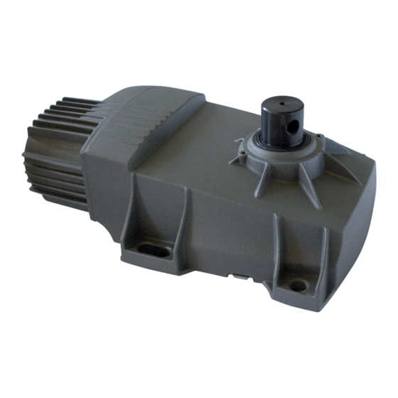
DUKE 24V
Scarica questo manuale sul tuo cellulare
Téléchargez ce manuel sur votre mobile
Download this manual on your mobile
Laden Sie dieses Handbuch auf Ihr Handy herunter
Descarga este manual en tu móvil
Operatore
Operateur
Operator
Torantrieb
Operador
DUKE 24V 110°
DUKE 24V 180°
Die korrekte Bedienung des Bedieners ist nur gewährleistet, wenn er von einem RIB-Bedienpanel verwaltet wird
ITALIANO pag. 05 / FRANÇAIS pag. 18 / ENGLISH page 31 / DEUTSCH pag. 44 / ESPAÑOL pag. 57
con / avec / with / mit
B2D 24V-CRX 230V 50/60Hz
B2D 24V-CRX 120V 60Hz
B2D 24V solo scheda, seule carte, only pc board, nür Karte, solo tarjeta de control
Alimentazione
Alimentation
Power Supply
Stromspannung
Alimentacion
24V
Il corretto funzionamento dell'operatore è garantito solo se viene gestito da un quadro di comando RIB
Le bon fonctionnement de l'opérateur n'est garanti que s'il est géré par un panneau de contrôle RIB
The correct operation of the operator is guaranteed only if it is managed by a RIB control panel
El funcionamiento correcto del operador solo está garantizado si está gestionado por un panel de control RIB
cod. ABB2060
cod. ABB2061
Vedere pagina 17
Voir page 30
See page 43
Siehe Seite 56
Ver página 69
Peso max cancello
Poids maxi portail
Max gate weight
Max Torgewicht
Peso máx verja
400Kg / 882 lbs
per anta 2 m / pour vantail 2 m / for 2 m
leaf / für Flügel 2 m / para puerta 2 m
B2D 24V-CRX
Manuali online interattivi
Manuels interactifs en ligne
Interactive online manuals
Interaktive Online-Handbücher
Manuales interactivos en línea.
Coppia max
Codice
Couple maxi
Code
Max torque
Code
Max. Drehmoment
Code
Coppia max
Codigo
AA10936
Nm 250
AA10938
cod. AC08072
Table des Matières

Manuels Connexes pour RIB DUKE 24V


Sommaire des Matières pour RIB DUKE 24V
- Page 1 Le bon fonctionnement de l’opérateur n’est garanti que s’il est géré par un panneau de contrôle RIB The correct operation of the operator is guaranteed only if it is managed by a RIB control panel Die korrekte Bedienung des Bedieners ist nur gewährleistet, wenn er von einem RIB-Bedienpanel verwaltet wird El funcionamiento correcto del operador solo está...
-
Page 2: Conserver Soigneusement Ces Instructions
2° - En ce qui concerne la section et le type des câbles, RIB conseille d’utiliser un câble de 2° - Per la sezione ed il tipo dei cavi la RIB consiglia di utilizzare un cavo di tipo H05RN-F con type H05RN-F ayant une section minumum de 1,5 mm et de toute façon, s’en tenir à... - Page 4 L’eliminazione dei materiali va fatta rispettando le norme vigenti. Non gettate il vostro 2° - Para la sección y el tipo de los cables, RIB aconseja utilizar cables de tipo H05RN-F con apparecchio scartato, le pile o le batterie usate nei rifiuti domestici. Avete la responsabilità di sección mínima de 1,5 mm...
-
Page 18: Schéma Détaillé De L'installation
DUKE est un opérateur irréversible équipé d’un fin de course mécanique et d’un couvercle de passage. DUKE 24V 110° est équipé d’un variateur de vitesse du vantail, tant en ouverture qu’en fermeture (ouverture lente au début puis rapide, fermeture rapide au début puis lente à... -
Page 19: Preparer La Scellement Du Caisson
- L’axe des gonds doit correspondre parfaitement à l’axe de l’arbre porte-levier d’entraînement. - Pour DUKE 24V 110°: Collez la boîte de fondation en vérifiant que ses côtés les plus courts sont parfaitement parallèles à la porte lorsqu’elle est FERMÉE. - Page 20 CME6987 ACG2120 ACG2125 ACG2130 CME5224 (DUKE 24V 110°) CME5230 (DUKE 24V 180°) DUKE 24V 110° DROIT 62 mm Tube pour ecoulement de l’eau CCA1360 Tube pour câbles électriques...
-
Page 21: Installation De Duke 24V
CME5226 tourné vers la butée 1 pour monter avec l’ouverture à gauche ou tourner vers la butée 2 pour monter avec l’ouverture à droite. REGLAGE DES FINS DE COURSE MECANIQUES DUKE 24V 180° - Fig.12 Pour arrêter le mouvement du portail dans les positions désirées, il suffit d’agir sur les vis Tube pour ecoulement de l’eau... -
Page 22: Branchements Électriques
BRANCHEMENTS ÉLECTRIQUES... - Page 23 Alimentation 230 Vac 50/60 Hz - externe à la fiche RADIO Connecteur pour module radio ACG8069 (120 V 60 Hz sur demande) Connecteur pour radio récepteur RIB à enclenchement avec RADIO A+TEST Positif pour alimentation autotest photocellules alimentation à 24Vdc BATTERY CHARGER Connecteur pour fiche de recharge batterie à...
-
Page 24: C - Contrôle Du Sens De Rotation Du/Des Moteur/S
B - RÉGLAGES avec des choses ou des personnes (en conformité avec les normes EN en vigueur - toujours vérifier avec les outils appropriés le respect des valeurs imposées par la norme EN12453. Activer le DIP 14 pour la mesure correcte). DIP 1 (ON) - COMMANDE SENS DE ROTATION DU MOTEURS (POINT C) Avec un impact en ouverture, il inverse le mouvement de fermeture pendant 1 s puis s’arrête. -
Page 25: D - Programmation Des Temps Pour 1 Moteur (M1)
SUN 2CH deux canaux - touches bleues et LED blanche cod. ACG6052 Grâce à l’application RIB GATE, il est possible de configurer le fonctionnement de ce relais à SUN 4CH quatre canaux - touches bleues et LED blanche cod. ACG6054 volonté. -
Page 26: Fonctionnement Des Accessoires De Commande
Mettre le DIP 9 sur ON pour activer le coup de désenclenchement de la serrure électrique en PROCEDURE D’EFFACEMENT DE TOUS LES CODES RADIO RESERVES A L’OUVERTURE PIETONNE ouverture (à condition que le DIP 8 soit sur ON). L’effacement ne peut s’effectuer que lorsque le portail est stationnaire. Lorsque le portail est fermé, si une commande d’ouverture est engagée, le portail effectue la 1 - Positionner DIP 1 sur ON, DIP 2 sur ON et ensuite DIP 3 sur ON. -
Page 27: Signalisations Visuelles Et Acoustiques
TCA et la LED DL11 allumée). - Courant sur le connecteur radio 200 mA TRAVAIL AVEC HOMME MORT (avec commande maintenue), DANS LE CAS DE PANNE DE SÉCURITÉ CARACTERISTIQUES TECHNIQUES RADIO (modèle B2D 24V-CRX) Si l’un des deux barre palpeuse est en panne ou engagé pour plus de 5 s, ou si l’un des deux photocellule est en panne ou engagée pour plus de 60 s, les commandes OPEN, CLOSE, START et - Fréquence réception 433,92 MHz... -
Page 28: Signalisations Pendant Le Fonctionnement
TABLEAU RÉCAPITULATIF ALARMES VISUELLES ET SONORES SIGNALISATIONS EN COURS DE PROGRAMMATION ÉVÉNEMENT ÉTAT BUZZER ÉTAT CLIGNOTEUR ÉTAT LED DL1 DIP 1 ON (mode homme mort) Éteint Éteint Clignote 250 ms ON/OFF Ou panne d'une sécurité DIP 2 ON (programmation course totale) Éteint Éteint Clignote 500 ms ON/OFF... -
Page 29: Débrayage Avec Cylindre Din
Absence de module radio dans le connecteur J6 ou module radio défectueux. OPTIONS Pour les branchements et les données techniques des accessoires, se conformer aux livrets d’instruction correspondants. CAISSE DE FONDATION POUR DUKE 24V 180° CAISSE DE FONDATION POUR DUKE 24V 110° code ACG8436... -
Page 30: Emetteur Radio Sun
BATTERIE FICHE DE CHARGE BATTERIE Batterie 2,2Ah 12V code ACG9515 code ACG4773 EMETTEUR RADIO SUN MODULE RADIO 433MHz SUN 2CH cod. ACG6052 SUN 4CH cod. ACG6054 cod. ACG8069 SUN CLONE 2CH cod. ACG6056 SUN CLONE 4CH cod. ACG6058 SUN-PRO 2CH cod. - Page 71 COLLEGAMENTI FOTOCELLULE - CONNEXIONS PHOTOCELLULE - PHOTOCELLS CONNECTIONS FOTOZELLEN VERBINDUNGEN - CONEXIONES FOTOCÉLULAS 4 fotocellule NOVA sincronizzate con autotest 4 photocellules NOVA synchronisées avec autotest 4 NOVA photocells synchronized with self-test 4 NOVA Photozellen synchronisiert mit Selbstkontrolle 4 fotocélulas NOVA sincronizadas con autotest COM/PHOT A+ TEST ATTENZIONE: Se si attiva la funzione AUTOTEST e si collega una sola fotocellula, si deve fare...
- Page 76 R.I.B. S.r.l. - Via Matteotti, 162 - 25014 Castenedolo - Brescia - Italy Tel. ++39.030.2135811 - www.ribind.it - ribind@ribind.it Apparecchio modello : Oggetto della dichiarazione : DUKE 24V Modèle d'appareil : Objet de la déclaration : Apparatus model : Object of the declaration :...