Dimplex SI 75TU Instructions D'installation Et D'utilisation
Les langues disponibles
Les langues disponibles
SI 50TU
SI 75TU
Montage- und
Gebrauchsanweisung
Sole-Wasser-
Wärmepumpe
für Innenaufstellung
Bestell-Nr. | Order no. | No de commande: 452237.66.50
Installation and
Operating Instruction
Brine-to-Water
Heat Pump for
Indoor Installation
Glen
Dimplex
Thermal
Solutions
Instuctions d'installation
et d'utilisation
Pompe à chaleur
eau glycolée-eau pour
installation intérieure
DE | EN | FR · FD 9912
Dimplex
Chapitres

Manuels Connexes pour Dimplex SI 75TU


Sommaire des Matières pour Dimplex SI 75TU
- Page 1 Glen Dimplex Thermal Solutions Dimplex SI 50TU SI 75TU Montage- und Installation and Instuctions d‘installation Gebrauchsanweisung Operating Instruction et d‘utilisation Sole-Wasser- Brine-to-Water Pompe à chaleur Wärmepumpe Heat Pump for eau glycolée-eau pour für Innenaufstellung Indoor Installation installation intérieure Bestell-Nr. | Order no. | No de commande: 452237.66.50...
- Page 34 English SI 50TU - SI 75TU EN-16 452237.66.50 · FD 9912 www.gdts.one...
- Page 35 SI 50TU - SI 75TU Français Table des matières À lire immédiatement..........................FR-2 1.1 Remarques importantes ..............................FR-2 1.2 Utilisation conforme................................ FR-2 1.3 Dispositions légales et directives..........................FR-3 1.4 Utilisation de la pompe à chaleur pour économiser de l’énergie ..............FR-3 Utilisation de la pompe à...
-
Page 36: Lire Immédiatement
Français SI 50TU - SI 75TU ATTENTION ! À lire immédiatement Tenir compte du champ magnétique rotatif vers la droite: si le câblage est mal effectué, la pompe à chaleur ne peut pas 1.1 Remarques importantes démarrer. Un avertissement correspondant s’affiche sur le gestionnaire de pompe à... -
Page 37: Dispositions Légales Et Directives
SI 50TU - SI 75TU Français 1.3 Dispositions légales et Utilisation de la pompe à directives chaleur Cette pompe à chaleur est conçue pour une utilisation dans un environnement domestique selon l’article1 (paragraphe 2k) de 2.1 Domaine d’utilisation la directive UE 2006/42/CE (directive relative aux machines) et est ainsi soumise aux exigences de la directive UE 2014/35/UE La pompe à... -
Page 38: Appareil De Base
Français SI 50TU - SI 75TU Appareil de base L'appareil de base comporte une pompe à chaleur pour instal- lation à l'intérieur, prête à brancher, avec jaquette en tôle, boî- tier électrique et gestionnaire de pompe à chaleur intégré. Le circuit frigorifique est «... -
Page 39: Accessoires
SI 50TU - SI 75TU Français Accessoires Transport Le transport par chariot élévateur convient bien à un dépla- 4.1 Brides de raccordement cement sur surface plane. Si la pompe à chaleur doit être convoyée sur une surface non plane ou dans des escaliers, il est Les brides de raccordement à... -
Page 40: Installation
Français SI 50TU - SI 75TU 7.2 Raccordement côté chauffage Installation ATTENTION ! 6.1 Remarques d'ordre général Rincer l'installation de chauffage avant de raccorder la pompe à chaleur. La pompe à chaleur eau glycolée/eau doit être installée dans un local sec à l’abri du gel, sur une surface plane, lisse et horizon- Avant de procéder aux raccordements de la pompe à... -
Page 41: Débit Minimum D'eau De Chauffage
SI 50TU - SI 75TU Français 7.4 Sonde de température Débit minimum d'eau de chauffage Le débit minimum d’eau de chauffage doit être garanti dans la Les sondes de température suivantes sont déjà montées ou pompe à chaleur quel que soit l’état de fonctionnement de doivent être installées en plus:... -
Page 42: Montage De La Sonde De Température Extérieure
Français SI 50TU - SI 75TU 7.4.2 Montage de la sonde de température 7.4.4 Système de distribution hydraulique extérieure Le distributeur compact et le distributeur double sans pression différentielle servent d’interface entre la pompe à chaleur, le La sonde de température doit être placée de telle sorte qu’elle circuit de distribution du chauffage, le ballon tampon et éven-... -
Page 43: Branchements Électriques
SI 50TU - SI 75TU Français 7.5 Branchements électriques 7.5.2 Branchements électriques La ligne d’alimentation électrique à 4fils de la partie puis- 7.5.1 Généralités sance de la pompe à chaleur est amenée du compteur de courant de la pompe à chaleur jusqu'à cette dernière (ten- Tous les branchements électriques doivent être effectués ex-... -
Page 44: Branchement Des Circulateurs À Régulation Électronique
Français SI 50TU - SI 75TU Le circulateur du circuit de chauffage (M13) est com- Mise en service mandé via le contact N1-J13/NO5. Les points de raccor- dement de la pompe sont X2/M13 et X2/N. En cas d'utili- 8.1 Remarques d'ordre général sation de pompes qui dépassent la capacité... -
Page 45: Entretien/Nettoyage
SI 50TU - SI 75TU Français 9.3 Nettoyage côté source de Entretien/nettoyage chaleur 9.1 Entretien ATTENTION ! Pour éviter des défauts dus à des dépôts dans les échangeurs Monter dans l’entrée de la source de chaleur de la pompe à... -
Page 46: Informations Sur Les Appareils
Français SI 50TU - SI 75TU 12 Informations sur les appareils Désignation technique et référence de commande SI 50TU SI 75TU Design Source de chaleur Eau glycolée Eau glycolée Version Universelle Universelle Régulateur intégré intégré Calorimètre intégré intégré Emplacement à l’intérieur à... -
Page 47: Autres Caractéristiques Techniques
SI 50TU - SI 75TU Français Conforme aux dispositions de sécurité européennes Autres caractéristiques techniques Eau de chauffage dans l’appareil protégée du gel Surpression de service max. (source de chaleur/dissipation thermique) bars Puissance calorifique/coefficient de performance EN 14511 EN 14511 Capacité... -
Page 48: Informations Sur Le Produit Conformément Au Règlmenet (Ue) N° 813
Glen Dimplex Deutschland GmbH, Am Goldenen Feld 18, 95326 Kulmbach Coordonnées de contact (*) Pour les dispositifs de chauffage des locaux par pompe à chaleur et les dispositifs de chauffage mixtes par pompe à chaleur, la puissance thermique nominale Prated est égale à... - Page 49 Glen Dimplex Deutschland GmbH, Am Goldenen Feld 18, 95326 Kulmbach Coordonnées de contact (*) Pour les dispositifs de chauffage des locaux par pompe à chaleur et les dispositifs de chauffage mixtes par pompe à chaleur, la puissance thermique nominale Prated est égale à...
- Page 50 Français SI 50TU - SI 75TU FR-16 452237.66.50 · FD 9912 www.gdts.one...
-
Page 51: Anhang
3.4 Anschlussplan / Connection Plan / Schéma de connexion SI 50TU - SI 75TU ..........A-X 3.5 Anschlussplan / Connection Plan / Schéma de connexion SI 50TU - SI 75TU ......... A-XI 3.6 Legende / Legend / Légende SI 50TU - SI 75TU ....................A-XII Hydraulische Einbindungsschemen / Hydraulic integration diagrams / Schémas d'intégration hydraulique...................... -
Page 52: Maßbilder / Dimension Drawings / Schémas Cotés
Anhang · Appendix · Annexes SI 50TU - SI 75TU 1 Maßbilder / Dimension Drawings / Schémas cotés 1.1 Maßbild / Dimension Drawing / Schéma coté SI 50TU A-II 452237.66.50 · FD 9912 www.gdts.one... -
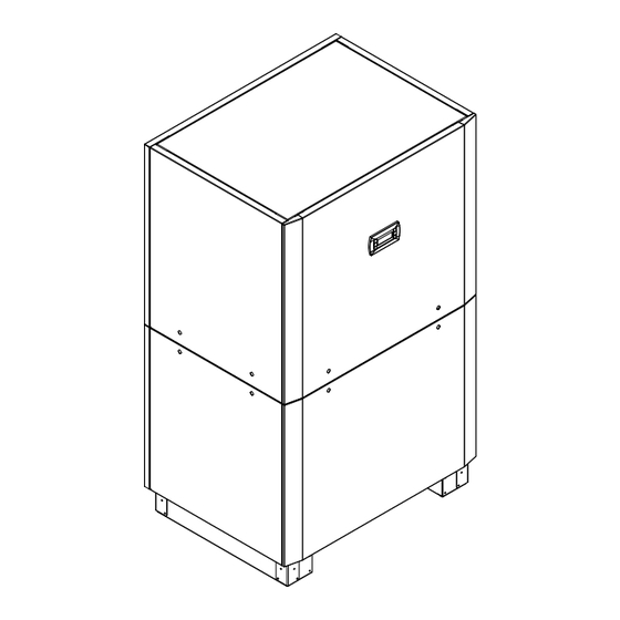
Page 53: Maßbild / Dimension Drawing / Schéma Coté Si 75Tu
SI 50TU - SI 75TU Anhang · Appendix · Annexes 1.2 Maßbild / Dimension Drawing / Schéma coté SI 75TU www.gdts.one 452237.66.50 · FD 9912 A-III... -
Page 54: Diagramme / Diagrams / Diagrammes
Anhang · Appendix · Annexes SI 50TU - SI 75TU 2 Diagramme / Diagrams / Diagrammes 2.1 Kennlinien / Characteristic Curves / Courbes caractéristiques SI 50TU Heizleistung in [kW] Wasseraustrittstemperatur in [°C] Heating capacity in [kW] Water outlet temperature in [°C] Puissance de chauffage en [kW] Température de sortie de l'eau en [°C]... -
Page 55: Kennlinien / Characteristic Curves / Courbes Caractéristiques Si 75Tu
SI 50TU - SI 75TU Anhang · Appendix · Annexes 2.2 Kennlinien / Characteristic Curves / Courbes caractéristiques SI 75TU Wasseraustrittstemperatur in [°C] Heizleistung in [kW] Water outlet temperature in [°C] Heating capacity in [kW] Température de sortie de l'eau en [°C]... -
Page 56: Einsatzgrenzendiagramm / Operating Limits Diagram / Diagramme Des Seuils D'utilisation
Anhang · Appendix · Annexes SI 50TU - SI 75TU 2.3 Einsatzgrenzendiagramm / Operating limits diagram / Diagramme des seuils d'utilisation Wasseraustritt (+/- 2 K) Water outlet (+/- 2 K) Sortie d'eau (+/- 2 K) Heizwasserdurchfluss min / max water flow rate min / max Débit d'eau de chauffage min / max... -
Page 57: Stromlaufpläne / Circuit Diagrams / Schémas Électriques
SI 50TU - SI 75TU Anhang · Appendix · Annexes 3 Stromlaufpläne / Circuit Diagrams / Schémas électriques 3.1 Steuerung / Control / Commande SI 50TU - SI 75TU www.gdts.one 452237.66.50 · FD 9912 A-VII... - Page 58 Anhang · Appendix · Annexes SI 50TU - SI 75TU 3.2 Steuerung / Control / Commande SI 50TU - SI 75TU A-VIII 452237.66.50 · FD 9912 www.gdts.one...
-
Page 60: Anschlussplan / Connection Plan / Schéma De Connexion Si 50Tu - Si 75Tu
Anhang · Appendix · Annexes SI 50TU - SI 75TU 3.4 Anschlussplan / Connection Plan / Schéma de connexion SI 50TU - SI 75TU 452237.66.50 · FD 9912 www.gdts.one... - Page 61 SI 50TU - SI 75TU Anhang · Appendix · Annexes 3.5 Anschlussplan / Connection Plan / Schéma de connexion SI 50TU - SI 75TU www.gdts.one 452237.66.50 · FD 9912 A-XI...
-
Page 62: Legende / Legend / Légende Si 50Tu - Si 75Tu
Anhang · Appendix · Annexes SI 50TU - SI 75TU 3.6 Legende / Legend / Légende SI 50TU - SI 75TU Brücke EVU-Sperre, muss eingelegt werden, wenn Utility block (EVU) bridge must be inserted if no Pont de blocage de la société d'électricité, à... - Page 63 SI 50TU - SI 75TU Anhang · Appendix · Annexes Sanftanlaufsteuerung M1 Soft start control M1 Commande de démarrage progressif M1 Sanftanlaufsteuerung M3 Soft start control M3 Commande de démarrage progressif M3 Bedienteil Control panel Unité de commande N17* pCOe-Modul...
-
Page 64: Hydraulische Einbindungsschemen / Hydraulic Integration Diagrams / Schémas D'intégration Hydraulique
Anhang · Appendix · Annexes SI 50TU - SI 75TU 4 Hydraulische Einbindungsschemen / Hydraulic integration diagrams / Schémas d'intégration hydraulique 4.1 Monovalente Wärmepumpenanlage mit 3 Heizkreisen und Warmwasserbereitung / Monovalent heat pump system with three heating circuits and domestic hot water preparation / Installation monovalente de pompe à... -
Page 65: Bivalente Wärmepumpenanlage Mit Zwei Heizkreisen Und Warmwasserbereitung / Bivalent System With Two Heating Circuits And Domestic Hot Water Preparation / Installation Bivalente Avec Deux Circuits De Chauffage Et Production D´eau Chaude Sanitaire
SI 50TU - SI 75TU Anhang · Appendix · Annexes 4.2 Bivalente Wärmepumpenanlage mit zwei Heizkreisen und Warmwasserbereitung / Bivalent system with two heating circuits and domestic hot water preparation / Installation bivalente avec deux circuits de chauffage et production d´eau chaude sanitaire www.gdts.one... -
Page 66: Legende / Legend / Légende
Anhang · Appendix · Annexes SI 50TU - SI 75TU 4.3 Legende / Legend / Légende Rückschlagventil Check valve Clapet anti-retour Absperrventil Shutoff valve Robinet d’arrêt Schmutzfänger Dirt trap Filtre Dreiwegemischer Three-way mixer Mélangeur 3 voies Umwälzpumpe Circulating pump Circulateur Ausdehnungsgefäß... -
Page 67: Konformitätserklärung / Declaration Of Conformity / Déclaration De Conformité
SI 50TU - SI 75TU Anhang · Appendix · Annexes 5 Konformitätserklärung / Declaration of Conformity / Déclaration de conformité Die aktuelle CE-Konformitätserklärung finden sie als Download unter: You can find and download the current CE conformity declaration at: Vous pouvez télécharger la déclaration de conformité CE actuelle sous : https://gdts.one/si50tu... - Page 68 Glen Dimplex Deutschland GmbH Irrtümer und Änderungen vorbehalten. Geschäftsbereich GDTS Subject to alterations and errors. Am Goldenen Feld 18 Sous réserve d’erreurs et modifications. D-95326 Kulmbach +49 (0) 9221 709 924545 www.gdts.one...