Table des Matières
Publicité
Les langues disponibles
Les langues disponibles
Liens rapides
INSTALLER:
Leave this manual with the appliance.
CONSUMER:
Retain this manual for future reference.
WARNING
FIRE OR EXPLOSION HAZARD
Failure to follow safety warnings exactly
could result in serious injury, death, or
property damage.
— Do not store or use gasoline or other
flammable vapors and liquids in the
vicinity of this or any other appliance.
— WHAT TO DO IF YOU SMELL GAS
•
Do not try to light any appliance.
•
Do not touch any electrical switch;
do not use any phone in your building.
•
Leave the building immediately.
•
Immediately call your gas supplier
from a neighbor's phone. Follow
the gas supplier's instructions.
•
If you cannot reach your gas
supplier, call the fire department.
— Installation and service must be
performed by a qualified installer,
service agency or the gas supplier.
DANGER
A barrier designed to reduce the risk of burns from the hot
viewing glass is provided with this appliance and must be
installed for the protection of children and other at-risk
individuals.
INSTALLATION INSTRUCTIONS
(SEE HOMEOWNER MANUAL FOR OPERATING INSTRUCTIONS)
HOT GLASS WILL
CAUSE BURNS.
DO NOT TOUCH GLASS
UNTIL COOLED.
NEVER ALLOW CHILDREN
TO TOUCH GLASS.
DIRECT - VENT ZERO
CLEARANCE GAS FIREPLACE
HEATER MODEL SERIES:
DVCTL60CFP95N
This appliance may be installed in an aftermarket,
permanently located, manufactured home (USA
only) or mobile home, where not prohibited by
local codes.
This appliance is only for use with the type
of gas indicated on the rating plate. This
appliance is not convertible for use with other
gases, unless a certified kit is used.
GAS-FIRED
UL FILE NO. MH30033
This fireplace is design
certified in accordance
with American National
Standard/CSA Standard
ANSI Z21.88/CSA 2.33
a n d b y U n d e r w r i t e r s
Laboratories as a Direct Vent
Gas Fireplace Heater and
shall be installed according
to these instructions.
Page 1
Publicité
Table des Matières
Dépannage

Manuels Connexes pour Empire Comfort Systems DVCTL60CFP95N


Sommaire des Matières pour Empire Comfort Systems DVCTL60CFP95N
- Page 1 Leave this manual with the appliance. CLEARANCE GAS FIREPLACE CONSUMER: HEATER MODEL SERIES: Retain this manual for future reference. DVCTL60CFP95N WARNING FIRE OR EXPLOSION HAZARD Failure to follow safety warnings exactly could result in serious injury, death, or property damage.
-
Page 2: Table Des Matières
TABLE OF CONTENTS SECTION PAGE Important Safety Information ............................3 Safety Information For Users Of Propane Gas ......................4 Requirements For Massachusetts ..........................5 Introduction ..................................6 Homeowner Reference Information ..........................6 Attention Installer .................................7 Before You Start ...............................8-9 Carton Contents And Hardware ..........................10 Specifications ................................11 Accessories ................................ -
Page 3: Important Safety Information
IMPORTANT SAFETY INFORMATION Before enclosing the vent pipe assembly, operate the appliance to ensure it is venting properly. DO NOT OPERATE THIS APPLIANCE WITHOUT GLASS FRONT PANEL INSTALLED WARNING 1. “Due to high temperatures, the appliance should be 6. “Clothing or other flammable material should not be located out of traffic and away from furniture and placed on or near the appliance.”... -
Page 4: Safety Information For Users Of Propane Gas
SAFETY INFORMATION FOR USERS OF PROPANE GAS Propane is a flammable gas which can cause fires and SOME POINTS TO REMEMBER explosions. In its natural state, propane is odorless and • Learn to recognize the odor of Propane Gas. Your local Propane colorless. -
Page 5: Requirements For Massachusetts
REQUIREMENTS FOR MASSACHUSETTS For all side wall horizontally vented gas fueled equipment installed INSPECTION. The state or local gas inspector of the side in every dwelling, building or structure used in whole or in part for wall horizontally vented gas fueled equipment shall not residential purposes, including those owned or operated by the approve the installation unless, upon inspection, the inspector Commonwealth and where the side wall exhaust vent termination... -
Page 6: Introduction
INTRODUCTION The information in this manual pertains to all models and gas control Fireplace Certification systems unless otherwise noted. This fireplace is design certified in accordance with American National Standard/CSA Standard ANSI Z21.88/CSA 2.33 and by Instructions To Installer Underwriters Laboratories as a Direct Vent Gas Fireplace Heater Leave this manual with Homeowner. -
Page 7: Attention Installer
This standard work checklist is to be used by the installer in conjunction with, not instead of, the instruction manual. Customer: _____________________________________ Date Installed: _________________________________ Lot/Address: ___________________________________ Fireplace Location: _____________________________ _______________________________________________ Installer: ______________________________________ DVCTL60CFP95N Model: ________________________________________ Dealer Phone #: ________________________________ Serial # ________________________________________ ______________________________________________ FIREPLACE INSTALLATION COMMENTS ____________________ Verified clearances to combustibles. -
Page 8: Before You Start
Installation of any damaged fireplace or component. • Modification of the fireplace or direct vent system. • Installation other than as instructed by Empire Comfort Systems. • Improper positioning of logs, glass door, or accessories. • Installation and/or use of any component part not manufactured or approved by Empire Comfort Systems. - Page 9 BEFORE YOU START (CONT’D) Preparation Accessories This fireplace and its components are safe when installed in Most accessories install much more easily before fitting the fireplace accordance with this Manual. Report any parts damaged in shipment to the opening. to your dealer. Do not install the fireplace with damaged, incomplete For example, it takes just 10-15 minutes to install the blower through or substitute parts.
-
Page 10: Carton Contents And Hardware
CARTON CONTENTS AND HARDWARE IMAGE NOT TO SCALE CARTON CONTENTS Index Number Description Quantity Supplied Unit AA Batteries Rockwool Drywall Screws Non-Combustible Board (On Pallet) Remote Support, Rockwool 2 X 1 Support, Rockwool 3 X 1 Support, Rockwool 6 X 1 Ember Bed (Not Shown) High Wind Shield Combustible Standoff... -
Page 11: Specifications
35w Clear Halogen, Bi-Pin 6.35mm base,120vac, UL ACCESSORIES The following accessory parts can be obtained from your Empire Comfort Systems dealer. For additional information beyond what your dealer can furnish, contact Empire Comfort Systems Inc., 918 Freeburg Ave., Belleville, Illinois 62220-2623. -
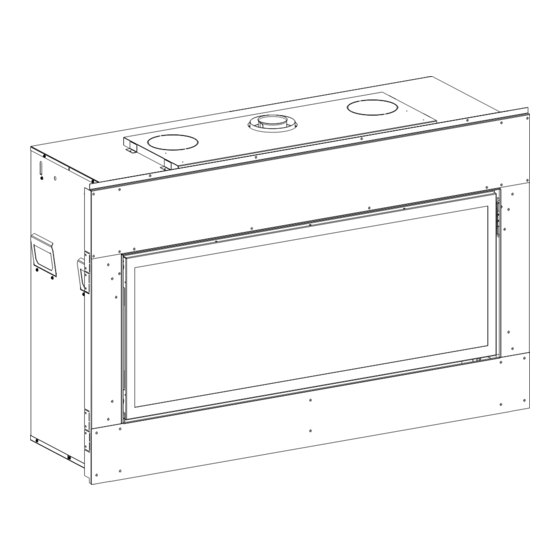
Page 12: Fireplace Dimensions
FIREPLACE DIMENSIONS Figure 1 DIMENSIONS (IN INCHES) INDEX DIMENSION DESCRIPTION LETTER DVCTL60 The maximum height of fireplace face 38-3/8 The maximum width of the fireplace face 74-5/8 The maximum depth of the fireplace 23-5/8 The height of the fireplace opening 29-3/8 The width of the fireplace opening 64-1/4... -
Page 13: Locating Fireplace
LOCATING FIREPLACE NOTICE: When installing this appliance against an exterior wall, insulate to applicable insulation CORNER CABINET codes. INSTALLATION INSTALLATION NOTICE: Island and Room Divider installation is possible as long as the horizontal portion of the vent system does not exceed 18 feet with ISLAND FLUSH WALL INSTALLATION... -
Page 14: Blower Installation
BLOWER INSTALLATION Remove protective connectors on Wire Assembly from fireplace CAUTION and discard. Connect Wire Harness to both blowers and the other end to the Wire Assembly supplied with the fireplace. See Sharp edges. Use protective gloves when installing. Figure 8. Bench Installation Remove Blower Access Panels. - Page 15 BLOWER INSTALLATION (CONT’D) Remove burner base. See Figure 11. Bend tab as shown in Figure 14 and secure with (2) screws. HAND BEND TAB INWARD HAND BEND TAB INWARD Figure 14 Remove protective connectors on Wire Assembly from fireplace and discard. Connect Wire Harness to both blowers and the Figure 11 other end to the Wire Assembly supplied with the fireplace.
-
Page 16: Clearances
CLEARANCES Mantel Chart CLEARANCE TO COMBUSTIBLES CEILING DIMENSIONS (In Inches) Back COMBUSTIBLES Side ALLOWED Floor WALL Top of Unit FACING 35” WALL FINISHED WALL 10” MIN. STUD (COMBUSTIBLE) 22” FRAMING HEADER MIN. NONCOMBUSTIBLE BOARD INSTALLED OVER APPLIANCE 12” MIN. OPENING OF FIREPLACE 72”... -
Page 17: Vent Termination Clearances
VENT TERMINATION CLEARANCES TERMINATION CLEARANCE FOR BUILDINGS WITH COMBUSTIBLE AND NONCOMBUSTIBLE EXTERIORS. INSIDE CORNER OUTSIDE CORNER RECESSED LOCATION A = COMBUSTIBLE 9” (229mm) F = COMBUSTIBLE 6” (152mm) = NONCOMBUSTIBLE 2” (51mm) = NONCOMBUSTIBLE 6” (152mm) BALCONY BALCONY WITH PERPENDICULAR SIDE WALL WITH NO SIDE WALL C = CLEARANCE FROM CORNER IN RECESSED LOCATION... - Page 18 Clearances are to heat resistant material (i.e. wood, metal). This the following shall be indicated: does not include vinyl. Empire Comfort Systems Inc. will not be held Clearance in accordance with local installation codes and the requirements of the responsible for heat damage caused from terminating under vinyl gas supplier.
-
Page 19: Gas Supply
GAS SUPPLY The gas pipeline can be brought in through the right side of the NOTICE: The gas controls are equipped with a captured screw-type fireplace. The fireplace has a Flexline with shut-off valve located pressure test point. It is not necessary to provide a 1/8-inch test on the right side when facing the fireplace. -
Page 20: Accessing Valve Compartment
ACCESSING VALVE COMPARTMENT Accessing Valve Compartment 4. Remove Access Panel. See Figure 27. 1. Remove the following items: See Figure 25. • Barrier Screen (See Maintenance and Service section for Instructions). • Glass Frame Assembly (See Maintenance and Service section for Instructions). Figure 27 Figure 25 2. -
Page 21: Testing The Gas Supply Pressure
TESTING THE GAS SUPPLY PRESSURE Natural Gas will have a manifold pressure of approximately 3.5 inches w.c. at the pressure regulator outlet with the inlet pressure to the pressure regulator from a minimum of 4.5 inches w.c. for the purpose of input adjustment to a maximum of 14 inches w.c. Propane Gas will have a manifold pressure approximately 10.0 inches w.c. -
Page 22: Installation
INSTALLATION Rough Opening For Floor Level Installation Figure 29 Rough Opening For Installing In Corner Figure 31 The fireplace can be mounted on any of the following surfaces: A flat, hard combustible or non-combustible surface. A raised wooden platform. Four corner supports. (Example: Four concrete masonry blocks.) These supports must be positioned so they contact all four perimeter edges on the bottom of the fireplace, if allowed by local codes. - Page 23 INSTALLATION (CONT’D) NAILING FLANGES NAILING FLANGES FOR 1/2" SECURED FOR 1/2” DRYWALL DRYWALL IN PLACE FOR 5/8" FOR 5/8” DRYWALL DRYWALL Figure 32 Figure 33 FLUSH WALL INSTALLATION FINISHED WALL NONCOMBUSTIBLE FINISHED BOARD INSTALLED FRAMING WALL OVER APPLIANCE HEADER NON-COMBUSTIBLE BOARD 21”...
- Page 24 INSTALLATION (CONT’D) Horizontal Vent Clearance Vent Runs For horizontal vent, maintain 1 inch of clearance to the bottom and In planning the installation, you must install certain components sides of vent, and 3 inches of clearance to combustibles above the before the fireplace is secured in position.
-
Page 25: Power Vent
POWER VENT CLEARANCE TO COMBUSTIBLES Back 0 inch Sides 0 inch Top/Bottom 0 inch 43902-0-1021 Page 25... - Page 26 POWER VENT ELECTRICAL CONNECTIONS ON FIREPLACE CAUTION All wiring should be done by a qualified electrician and shall be in compliance with all local, city and state building codes. Before making the electrical connection, make sure that the main power supply is disconnected. The fireplace, when installed, must be electrically grounded in accordance with local codes, or in the absence of local codes, with the National Electrical Code ANSI/NFPA 70 (Latest Edition).
- Page 27 POWER VENT VENT INFORMATION Insert a strain relief bushing through the 7/8 inch hole on the rear panel and insert minimum 18 gauge wiring (field Begin the vent system installation by identifying the path the vent supplied). See Figure 40 below. will take from the fireplace to the power-vent.
- Page 28 POWER VENT EFFECTIVE LENGTH IS CALCULATED BY THE FOLLOWING EQUATION: Equation 1 Effective length=Vertical Run Up + (2 × Vertical Run Down) + Horizontal Run + (3 × # of 90° elbows) +(1.5 × # of 45° elbows Figure 43 EXAMPLE 2 Total Fireplace...
- Page 29 POWER VENT MINIMUM EFFECTIVE LENGTH 2’ NOTE: MINIMUM EFFECTIVE 1’ LENGTH IS 10 FT FOR NATURAL AND 15 FT FOR PROPANE. Figure 45 INSTALLING FIRESTOPS Firestops are required for safety whenever the vent system passes through an interior wall, an exterior wall, or a ceiling. These firestops act as a firebreak heat shield and as a means to insure that minimum clearances are maintained to the vent system.
- Page 30 POWER VENT Vertical runs of this system which pass through ceilings require the use of one ceiling firestop at the hole in each ceiling through which the vent passes. Position a plumb bob directly over the center of the vertical vent component and mark the ceiling to establish the center point of the vent.
- Page 31 POWER VENT INSTALLATION Framing Once termination location has been determined build a frame with material that has the same dimensions as the current wall. As shown in Figure 52. The box must be 9-1/2 inches tall by 14-1/2 inches wide. COMBUSTIBLE STAND-OFF GASKET HORIZONTAL FASCIA...
-
Page 32: High Wind Applications
POWER VENT MAINTENANCE AND SERVICE PAINTING POWER-VENT This Power-Vent has no user-serviceable mechanical components. Front fascia and inlet air box can be painted if desired. All surfaces Contact your dealer or a qualified gas appliance service technician to be painted must be thoroughly cleaned and scuffed with steel for all service and repair. -
Page 33: Damper Adjustment
DAMPER ADJUSTMENT Damper Adjustment This unit has an adjustable damper for use with vertically terminated units only. The damper is shipped in a fully open position and may be adjusted per installation. To adjust, loosen the Phillip screw and rotate handle towards the left to close. We recommend a 1/3 closed on installations above 30 ft. -
Page 34: Air Shutter Adjustment
AIR SHUTTER ADJUSTMENT This Unit Is Equipped With Adjustable Air Shutters (2). 3. Replace glass door. See maintenance and service section of this manual. The air shutters may be adjusted externally while unit is burning. The unit is sent out with the recommended setting, but may need 4. -
Page 35: Multifunction Remote Operating Instructions
MULTIFUNCTION REMOTE OPERATING INSTRUCTIONS Figure 67 TECHNICAL DATA Remote Control Supply Voltage 4.5 V (three 1.5 V AAA batteries) Ambient Temperature Ratings 0-50°C (32 - 122°F) Radio Frequency 315 MHz WARNING The transmitter and receiver are radio frequency devices. Placing the receiver in or near metal may severely reduce the signal range. - Page 36 MULTIFUNCTION REMOTE OPERATING INSTRUCTIONS Temperature Indication Display °C or °F Remote Flame Control With the system in the “OFF” position, press the Thermostat But- The Proflame has six flame levels. With the system on, and the ton and the Mode Button at the same time. Look at the LCD screen flame level at the maximum in the appliance, pressing the Down on the Transmitter to verify that a °C or °F is visible to the right of Arrow Button once will reduce the flame height by one step until...
- Page 37 MULTIFUNCTION REMOTE OPERATING INSTRUCTIONS Smart Thermostat (Transmitter Operation) The Smart Thermostat function adjusts the flame height in accor- dance to the difference between the set point temperature and the actual room temperatures. As the room temperature gets closer to the set point the Smart Function will modulate the flame down. To activate this function, press the Thermostat Button until the word “SMART”...
- Page 38 MULTIFUNCTION REMOTE OPERATING INSTRUCTIONS Blower Control (Fan) If the appliance is equipped with a hot air circulating fan, the speed of the fan can be controlled by the Proflame system. The fan speed can be adjusted through six speeds. To activate this function, use the Mode Button Figure 68 to index the fan control icon.
- Page 39 MULTIFUNCTION REMOTE OPERATING INSTRUCTIONS Remote Auxiliary Relay Control (optional with this fireplace) Low Battery Power Detection - Transmitter The auxiliary function controls the AUX relay outlet. To activate this The life span of the remote control batteries depends on various function use the Mode Button Figure 68 to index to the AUX icon factors: quality of the batteries used, the number of ignitions of Figures 86 and 87.
- Page 40 MULTIFUNCTION REMOTE OPERATING INSTRUCTIONS Lockout State Definition A lockout state is reached when an ignition error occurs. The lockout state will remain set in memory as long as the power supplies are applied. This could mean both an irregular flame detection and/or too many unsuccessful ignition attempts.
-
Page 41: Control System Troubleshooting
CONTROL SYSTEM TROUBLESHOOTING If the IFC is signaling lock out: The Verify the electrical connections’ integrity and board should be unlocked to make sure they are in accordance with the relevant reinitiate a pilot flame ignition (for Is the IFC board in system wiring diagram. - Page 42 CONTROL SYSTEM TROUBLESHOOTING (CONT’D) Replace IFC board. Main burner lights when the pilot only Replace the gas valve. should light. Verify the pilot flame fully engulfs the tip of the sense electrode. If not, replace the pilot assembly. Replace the pilot assembly. Carefully clean the electrical connections of the sense cable and the IFC board sense cable connection.
-
Page 43: Maintenance And Service
MAINTENANCE AND SERVICE Remove old light bulb and replace with a new one. Glass And Barrier Removal See Figure 93. Lift barrier screen and pull towards you. Remove 3 bolts at the bottom edge of the glass frame using a NOTE: You may order light bulbs from your local Empire dealer 9/16"... - Page 44 MAINTENANCE AND SERVICE (CONT’D) Maintenance Precautions FOR INSTALLER Annual Inspection Installation and repair should be done by a qualified service person. The fireplace should be inspected before use and at least annually • Have the fireplace inspected annually before use. by a qualified service person.
-
Page 45: Component Wiring Diagram
COMPONENT WIRING DIAGRAM PILOT TO LIGHTS GREEN ORANGE YELLOW AUX. SPLIT FLOW SOLENOID WHITE IF ANY OF THE ORIGINAL WIRE AS SUPPLIED BLACK WITH THIS UNIT MUST BE REPLACED, IT MUST BE REPLACED WITH EQUIVALENT GAUGE AND TEMPERATURE RATED WIRE. SI FIL ORIGINAL L'UN DES COMME FOURNI AVEC GAS CONTROL VALVE LOOP... - Page 46 COMPONENT WIRING DIAGRAM (CONT'D) BLACK BLACK GREEN / YELLOW GREEN/YELLOW BLACK WHITE BLACK WHITE BLACK FIREPLACE BLACK FIREPLACE WHITE JUNCTION WHITE JUNCTION BOX GREEN GREEN BLACK BLACK GREEN GREEN BLACK BLACK WHITE WHITE Power Vent Wiring Diagram Figure 95 Bottom of Receiver Module Top of Receiver Module Figure 96 Figure 97...
-
Page 47: Parts List
PARTS LIST INDEX DVCTL60 INDEX DVCTL60 DESCRIPTION DESCRIPTION PART# PART# 43951 Heat Shield, Top 43729 Burner Wall Access Plate R11963 Insulation 43728 Burner Wall 43723 Outer Top 30947 Valve Bracket R13378 Insulation (2) 34741 Valve Bracket-Support Fireplace Painted Assembly 33332 Junction Box Heat Shield 43741 Glass Frame Assembly... -
Page 48: Exploded View
EXPLODED VIEW 27 26 Page 48 43902-0-1021... -
Page 49: Master Parts Distributor List
For the current list, please click on the Master Parts button at www.empirecomfort.com. Please note: Master Parts Distributors are independent businesses that stock the most commonly ordered Original Equipment repair parts for Heaters, Grills, and Fireplaces manufactured by Empire Comfort Systems Inc. Dey Distributing F. -
Page 50: Warranty
WARRANTY Empire Comfort Systems Inc. warranties this hearth product to be free from defects at the time of purchase and for the periods specified below. Hearth products must be installed by a qualified technician and must be maintained and operated safely, in accordance with the instructions in the owner’s manual. -
Page 51: Appliance Service History
APPLIANCE SERVICE HISTORY Date Dealer Name Service Technician Name Service Performed/Notes 43902-0-1021 Page 51... - Page 52 Empire Comfort Systems Inc. Belleville, IL If you have a general question about our products, please e-mail us at info@empirecomfort.com. If you have a service or repair question, please contact your dealer. www.empirecomfort.com Page 52 43902-0-1021...
- Page 53 DIRECTE SÉRIE DE ACHETEUR : MODÈLES DE CHAUFFAGE Conservez ce manuel pour référence ltérieure. DE CHEMINÉE À GAZ: DVCTL60CFP95N AVERTISSEMENT RISQUE D’INCENDIE OU D’EXPLOSION Veiller à respecter scrupuleusement les mises en garde, sous peine de blessures graves, de mort ou de dégâts matériels.
- Page 54 TABLE DES MATIÈRES SECTION PAGE Informations de sécurité importantes ..........................3 Consignes de sécurité pour les utilisateurs de gaz Propane ..................4 Exigences pour le Massachusetts ..........................5 Introduction ..................................6 Information de référence pour le propriétaire ......................6 À l’attention de l’installateur ............................7 Avant de commencer .............................. 8-9 Contenu de l’emballage et de la trousse de quincaillerie ..................10 Spécifications ................................11 Accessoires ................................11...
-
Page 55: Consignes De Sécurité Importantes
CONSIGNES DE SÉCURITÉ IMPORTANTES Avant d’emmurer le conduit d’évacuation, faire fonctionner l’appareil pour s’assurer que l’évacuation des gaz brûlés se fait correctement. NE PAS FAIRE FONCTIONNER CET APPAREIL SANS SA VITRE FRONTALE EN PLACE AVERTISSEMENT « En raison des températures élevées, l’appareil doit être «... -
Page 56: Consignes De Sécurité Pour Les Utilisateurs De Gaz Propane
CONSIGNES DE SÉCURITÉ POUR LES UTILISATEURS DE GAZ PROPANE Le propane est un gaz inflammable pouvant provoquer des CERTAINS POINTS À GARDER À L’ESPRIT incendies et des explosions. À l’état naturel, le propane est inodore • Apprendre à reconnaître l’odeur du gaz propane. Le fournisseur et incolore. -
Page 57: Exigences Pour Le Massachusetts
EXIGENCES POUR LE MASSACHUSETTS Pour tout appareil au gaz à ventilation horizontale murale posé dans INSPECTION. L’inspecteur local de gaz de l’équipement des habitations, bâtiments ou structures utilisés exclusivement ou au gaz à évacuation horizontale murale n’approuvera pas partiellement à des fins résidentielles, y compris ceux détenus l’installation à... -
Page 58: Introduction
INTRODUCTION Les renseignements contenus dans ce manuel s’appliquent à tous Consulter les autorités compétentes en matière de code du les modèles et à tous les systèmes de commande du gaz, sauf bâtiment avant la pose, pour assurer la conformité avec les codes indication contraire. -
Page 59: À L'attention De L'installateur
Utiliser cette liste de vérification en conjonction avec les instructions de ce manuel. Client : ________________________________________ Date d’installation : ______________________________ Lot/adresse : ___________________________________ Emplacement du foyer : __________________________ _______________________________________________ Installateur : ____________________________________ DVCTL60CFP95N Modèle : _______________________________________ N° tél. revendeur : _______________________________ N° de série : ____________________________________ _______________________________________________ INSTALLATION DU FOYER OBSERVATIONS ____________________ Vérifié... -
Page 60: Avant De Commencer
• Installation et/ou utilisation de tout élément non fabriqué ni approuvé par Empire Comfort Systems. Toute correspondance doit comporter le numéro de modèle com- plet, le numéro de série et le type de gaz. Remplir la section Infor- mation de référence pour le propriétaire à la page 6. -
Page 61: Avant De Commencer (Suite)
AVANT DE COMMENCER (SUITE) Préparation Accessoires Le foyer et ses composants sont sans danger s’ils sont installés La plupart des accessoires se posent beaucoup plus facilement conformément aux instructions du présent manuel. Déclarer au avant de positionner le foyer dans l’ouverture. revendeur tous les dommages subis durant le transport. -
Page 62: Contenu Du Carton Et Quincaillerie
CONTENU DU CARTON ET QUINCAILLERIE IMAGE NON A L'ECHELLE CONTENU DU CARTON Numéro d'index La description Quantité fournie Unité Piles AA Rockwool Vis à cloison sèche Planche non combustible (sur palette) Télécommande Soutien, Rockwool 2 X 1 Soutien, Rockwool 3 X 1 Soutien, Rockwool 6 X 1 Lit de braises (non illustré) Bouclier de vent élevé... -
Page 63: Caractéristiques
Les pièces accessoires suivantes peuvent être obtenues auprès de votre revendeur Empire Comfort Systems. Pour plus d'informations au- delà de ce que votre revendeur peut fournir, contactez Empire Comfort Systems Inc., 918 Freeburg Ave., Belleville, Illinois 62220-2623. KIT DE CONVERSION ACCESSOIRES Numéro... -
Page 64: Dimensions Du Foyer
DIMENSIONS DU FOYER Figure 1 DIMENSIONS (EN PO) INDICE DIMENSIONS DESCRIPTIF LETTRE DVCTL60 La hauteur maximale de la façade du foyer 38-3/8 (965.2 mm) La largeur maximale de la façade du foyer 74-5/8 (1879.6 mm) La profondeur maximale de la cheminée 23-5/8 (584.2 mm) La hauteur de l'ouverture de la cheminée 29-3/8 (736.6 mm) -
Page 65: Placement Du Foyer
EMPLACEMENT DU FOYER AVIS : Lors de l'installation de cet appareil contre un mur extérieur, isolez conformément aux codes POSE EN COIN INSTALLATION d'isolation applicables. DE L'ARMOIRE AVIS : L'installation de l'îlot et du diviseur de pièce est possible tant que la partie horizontale du système INSTALLATION de ventilation ne dépasse pas 18... -
Page 66: Installation De La Ventilateur
INSTALLATION DE LA VENTILATEUR Retirer les connecteurs de protection sur le câblage du foyer et ATTENTION les jeter. Raccorder le faisceau de câbles aux deux souffleries et l’autre extrémité à l’ensemble de câblage fourni avec le Bords tranchants. Porter des gants protecteurs durant la pose. foyer. -
Page 67: Installation De La Ventilateur (Suite)
INSTALLATION DE LA VENTILATEUR (SUITE) Déposer la plaque sous le brûleur. Voir Figure 11. Plier la patte, tel qu’illustré à la Figure 14 et la fixer solidement à l’aide de deux (2) vis. ONGLET DE PLIAGE À LA MAIN VERS L'INTÉRIEUR ONGLET DE PLIAGE À... -
Page 68: Dégagements
DÉGAGEMENTS Tableau de Cheminée DÉGAGEMENT AUX COMBUSTIBLES DIMENSIONS (en pouces) Arrière Côté 3 (76.2 mm) Haut de l'unité 36 (914.4 mm) DISTANCE DE DISTANCE DU SOMMET LETTRE FACE AU MUR D'OUVERTURE D'INDEX Dimensions (en pouces) 12 (304.8 mm) Figure 17 13-5/8 (330.2 mm) AVIS : Utilisez uniquement des matériaux non combustibles pour 15-5/16 (381 mm) -
Page 69: Dégagements De Terminaison D'évent
DÉGAGEMENTS DE TERMINAISON D'ÉVENT DÉGAGEMENTS À LA SORTIE D’ÉVACUATION POUR LES BÂTIMENTS À PAREMENT EXTÉRIEURS COMBUSTIBLES ET NON COMBUSTIBLES. ANGLE ENTÉRIEUR ANGLE EXTÉRIEUR EMPLACEMENT EN RETRAIT A = COMBUSTIBLE 9 po (229 mm) F = COMBUSTIBLE 6 po (152 mm) = NON COMBUSTIBLE 2 po (51 mm) = NON COMBUSTIBLE 6 po (152 mm) BALCON AVEC MUR LATÉRAL... -
Page 70: Dégagements De Terminaison D'évent (Suite)
Prévoir des dégagements en conformité avec les codes d’installation locaux et les exigences du fournisseur de gaz. Empire Comfort Systems Inc. ne sera pas tenu responsable des dommages de la chaleur causée par les extrémités d’évacuation débouchant sous des surplombs en vinyle, des plafonds en vinyle ou des soffites en vinyle ventilés ou non ventilés. -
Page 71: Alimentation En Gaz
ALIMENTATION DE GAZ La conduite de gaz peut pénétrer par le côté droit du foyer. Le foyer AVIS : Les commandes de gaz comportent un point d’essai de comporte une conduite flexible à robinet d’arrêt sur le côté droit, vu depuis pression à... -
Page 72: Accès Au Compartiment Vanne
ACCÈS AU COMPARTIMENT VANNE Accès au compartiment des vannes Retirez le panneau d'accès. Voir la Figure 27. Retirez les éléments suivants : Voir Figure 25. • Écran de barrière (Voir la section Entretien et service pour les instructions). • Assemblage du cadre en verre (voir la section Entretien et service pour les instructions). -
Page 73: Tester La Pression D'alimentation En Gaz
TESTER LA PRESSION D'ALIMENTATION EN GAZ Le gaz Naturel aura une pression d'admission d'environ 3.5 pouces w.c. à la sortie du régulateur de pression avec une pression d'entrée au régulateur de pression d'un minimum de 4.5 pouces w.c. à des fins d'ajustement de l'entrée à... -
Page 74: Installation
INSTALLATION Ouverture brute pour une installation au niveau du sol Figure 29 Ouverture brute pour l'installation dans le coin Figure 31 Le foyer peut être monté sur l'une des surfaces suivantes : Une surface plane, dure, combustible ou non combustible. Une plate-forme en bois surélevée. -
Page 75: Installation (Suite )
INSTALLATION (SUITE ) BRIDES DE CLOUAGE POUR BRIDES DE NAILING CLOISONS CLOUAGE FLANGES SÉCURISÉES SÈCHES 1/2" SECURED FOR 1/2” DRYWALL EN PLACE (12.7 mm) IN PLACE POUR FOR 5/8” DRYWALL CLOISONS SÈCHES 5/8" (15.875 mm) Figure 32 Figure 33 INSTALLATION MURALE AFFLEURANTE PANNEAU NON MUR FINI FINISHED WALL... - Page 76 INSTALLATION (SUITE) Dégagement d'évent horizontal Conduites d'aération Pour un évent horizontal, maintenez un dégagement de 1 pouce Lors de la planification de l'installation, vous devez installer cer- au bas et sur les côtés de l'évent et de 3 pouces aux matériaux tains composants avant que le foyer ne soit fixé...
-
Page 77: Évent De Puissance
ÉVENT DE PUISSANCE ARRIÈRE 0" HAUT 0" 13 29/32" CÔTÉ 0" 1 13/16" 5 23/32" 13 29/32" 1 13/16" 5 23/32" BAS 0" DÉGAGEMENT AUX COMBUSTIBLES Retour 0 po Côtés 0 po Haut/Bas 0 po 17 1/2" 13-29/32" 17-1/2" (330.2 mm) 13 29/32"... - Page 78 ÉVENT DE PUISSANCE CONNEXIONS ÉLECTRIQUES SUR LE FOYER ATTENTION Tout le câblage doit être effectué par un électricien qualifié et doit être conforme à tous les codes du bâtiment locaux, municipaux et nationaux. Avant d'effectuer la connexion électrique, assurez-vous que l'alimentation principale est déconnectée.
- Page 79 ÉVENT DE PUISSANCE INFORMATION SUR L’ÉVACUATION Insérer une douille de serre-câble à travers l’orifice de 7/8 po (22 mm) sur le panneau arrière et insérer des câbles de Pour démarrer l’installation du système d’évacuation, identifier le calibre minimum 18 (non fournis). Voir Figure 40 ci-dessous. trajet que va suivre le conduit entre le foyer et le caisson d’évacuation forcée.
- Page 80 ÉVENT DE PUISSANCE LA LONGUEUR EFFICACE EST CALCULÉE PAR L'ÉQUATION SUIVANTE : Équation 1 Longueur effective = Course verticale vers le haut + (2 × course verticale vers le bas) + Course horizontale + (3 × # de coudes à 90°) + (1,5 ×...
- Page 81 ÉVENT DE PUISSANCE LONGUEUR EFFECTIVE MINIMALE SANGLE DE TUYAU 2’ D'ÉTUDE (.6096 m) NOTE: SORTIE LA LONGUEUR DE FUMÉE EFFECTIVE MINIMALE EST DE 3,048 M (10 PI) 1’ POUR LE NATUREL (.3048 m) ET 15 PIEDS (4,572 M) POUR LE PROPANE. Figure 45 INSTALLATION COUPE-FEU Des coupe-feu sont nécessaires pour la sécurité...
- Page 82 ÉVENT DE PUISSANCE Les portions verticales du système d’évacuation qui traversent ONGLES, (4) REQUIS des plafonds nécessitent l’emploi d’un coupe-feu de plafond dans COUPE-FEU PLAFOND l’ouverture de chaque plafond traversé par le conduit. Placer un fil à plomb directement au-dessus du centre du conduit vertical pour établir et marquer le centre du conduit au plafond.
- Page 83 ÉVENT DE PUISSANCE INSTALLATION Charpente Une fois que l’emplacement de l’extrémité d’évacuation a été déterminé, construire un cadre avec des matériaux de mêmes dimensions que le mur existant. Voir Figure 52. Le jour doit mesurer 9-1/2 po (24,1 cm) de haut sur 14-1/2 po (36,8 cm) de large.
-
Page 84: Applications À Fort Vent
ÉVENT DE PUISSANCE ENTRETIEN ET SERVICE PEINTURE POWER-VENT Cet évent n'a aucun composant mécanique utilisable par l'utilisateur. Le carénage avant et la boîte à air d'entrée peuvent être peints Contactez votre concessionnaire ou un technicien qualifié pour si vous le souhaitez. Toutes les surfaces à peindre doivent être l'entretien et la réparation des appareils à... -
Page 85: Réglage De L'amortisseur
RÉGLAGE DE L'AMORTISSEUR Réglage de l'Amortisseur Cet appareil dispose d'un amortisseur réglable pour une utilisation uniquement avec des unités à terminaison verticale. L'amortisseur est livré en position complètement ouverte et peut être réglé par installation. Pour le régler, desserrez la vis cruciforme et tournez la poignée vers la gauche pour la fermer. -
Page 86: Réglage De L'obturateur D'air
RÉGLAGE DE L'OBTURATEUR D'AIR Cette Unité Est Équipée De Volets D'Aération Réglables (2). Remplacer la porte vitrée. Voir la section entretien et entretien de ce manuel. Les volets d'aération peuvent être réglés à l'extérieur pendant que l'appareil brûle. L'appareil est envoyé avec le réglage recommandé, Allumez l'appareil, consultez les instructions d'utilisation dans mais peut avoir besoin d'être réglé... -
Page 87: Instructions D'utilisation De La Télécommande Multifonction
INSTRUCTIONS D’UTILISATION DE LA TÉLÉCOMMANDE MULTIFONCTION Verrouillage enfants Émission Indicateur de décharge des piles Thermostat OFF/ON/SMART Thermostat OFF/ON/SMART Température (Arrêt/Marche/Intelligent) (Arrêt/Marche/Intelligent) de la pièce Mode CPI Valeur de réglage Aux activé Température/niveau/état Flamme activée Alimentation divisée/arrêt du brûleur central Éclairage Ventilateur de confort Figure 67 DONNÉES TECHNIQUES... - Page 88 UTILISATION DE LA TÉLÉCOMMANDE MULTIFONCTION Affichage de la température en °C ou °F Commande de la flamme à distance Le système étant en position « OFF » (Arrêt), appuyer sur la touche Le Proflame a six niveaux de flamme. Le système étant en marche et Thermostat et la touche Mode en même temps.
- Page 89 INSTRUCTIONS D’UTILISATION DE LA TÉLÉCOMMANDE MULTIFONCTION Thermostat intelligent (fonctionnement de l’émetteur) La fonction de thermostat intelligent (Smart) ajuste la hauteur de flamme en fonction de la différence entre la valeur de réglage de la température et la température réelle dans la pièce. À mesure que la température de la pièce approche la valeur de réglage, la fonction Smart réduit la hauteur de flamme.
- Page 90 INSTRUCTIONS D’UTILISATION DE LA TÉLÉCOMMANDE MULTIFONCTION Commande de la soufflante (ventilateur) Si l’appareil est équipé d’un ventilateur de circulation d’air chaud, la vitesse du ventilateur peut être régulée par le système Proflame. Le ventilateur présente six réglages de vitesse. Pour activer cette fonction, utiliser la touche Mode à...
- Page 91 INSTRUCTIONS D’UTILISATION DE LA TÉLÉCOMMANDE MULTIFONCTION Télécommande de relais auxiliaire (en option avec ce foyer) DÉTECTION DE DÉCHARGE DES PILES - ÉMETTEUR La fonction auxiliaire commande la prise du relais AUX. Pour activer L’autonomie des piles de la télécommande dépend de divers facteurs : cette fonction, utiliser la touche Mode à...
- Page 92 INSTRUCTIONS D’UTILISATION DE LA TÉLÉCOMMANDE MULTIFONCTION DÉFINITION DE L’ÉTAT BLOQUÉ Un état bloqué est atteint lorsqu’il se produit une erreur d’allumage. L’état bloqué reste en mémoire aussi longtemps que les alimentations électriques sont appliquées. Cela peut signifier qu’une flamme irrégulière est détectée ou qu’il s’est produit trop d’échecs d’allumage.
-
Page 93: Dépannage Du Système De Contrle
DÉPANNAGE DU SYSTÈME DE CONTRLE 43902-0-1021 Page 41... -
Page 94: Dépannage Du Système De Contrle (Suite)
DÉPANNAGE DU SYSTÈME DE CONTRLE (SUITE) 1. Remplacer la carte DFC. Le brûleur principal s’allume lorsque 2. Remplacer la soupape de seulement la veilleuse gaz. devrait s’allumer. 1. S’assurer que la flamme de la veilleuse englobe complètement l’extrémité de l’électrode du capteur. Si non remplacer l’ensemble veilleuse. -
Page 95: Entretien Et Service
ENTRETIEN ET SERVICE Dépose de la vitre et de l’écran de protection Démonter l’ampoule usagée et la remplacer par une neuve. Voir Figure 93. Soulever l’écran de protection et le tirer vers soi. Retirer les 3 boulons sur le bord inférieur de l’encadrement REMARQUE : Les ampoules peuvent être commandées auprès du de vitre à... -
Page 96: Entretien Et Service (Suite)
ENTRETIEN ET SERVICE (SUITE) Précautions d'entretien POUR L'INSTALLATEUR Inspection annuelle L'installation et la réparation doivent être effectuées par un technicien qualifié. Le foyer doit être inspecté avant utilisation et • Faites inspecter le foyer chaque année avant de l'utiliser. au moins une fois par an par un technicien qualifié. Un nettoyage •... -
Page 97: Schéma De Câblage Des Composants
SCHÉMA DE CÂBLAGE DES COMPOSANTS IF ANY OF THE ORIGINAL WIRE AS SUPPLIED WITH THIS UNIT MUST BE REPLACED, IT MUST BE REPLACED WITH EQUIVALENT GAUGE AND TEMPERATURE RATED WIRE. SI FIL ORIGINAL L'UN DES COMME FOURNI AVEC CETTE UNITÉ DOIT ÉTRE REMPLACÉ, IL DOIT REPLCED AVEC LA MESURE ÉQUIVALENTE ET LE FIL ÉVALUÉ... -
Page 98: Schéma De Câblage Des Composants (Suite)
SCHÉMA DE CÂBLAGE DES COMPOSANTS (SUITE) ROUGE BLACK NOIR BLACK GREEN / VERT/ ROUGE JAUNE YELLOW GREEN/YELLOW NOIR BLANC WHITE BLACK WHITE BOÎTE DE NOIR BLACK FIREPLACE BLACK JONCTION BLANC FIREPLACE WHITE JUNCTION WHITE JUNCTION BOX GREEN VERT GREEN CHEMINÉE BLACK NOIR BLACK... -
Page 99: Nomenclature Des Pièces
NOMENCLATURE DES PIÈCES DVCTL60 DVCTL60 DESCRIPTION DESCRIPTION D'INDEX PARTIE# D'INDEX PARTIE# 43951 Bouclier thermique, Haut 43729 Plaque d'Accès Murale du Brûleur R11963 Isolation 43728 Mur de Brûleur 43723 Dessus Extérieur 30947 Support de Valve R13378 Isolation (2) 34741 Support de Valve - Support Ensemble Peint de Cheminée 33332 Bouclier Thermique de Boîte de Jonction... -
Page 100: Vue Des Pièces
VUE DES PIÈCES 27 26 Page 48 43902-0-1021... -
Page 101: Liste Des Principaux Distributeurs De Pièces
Master Parts à www.empirecomfort.com. Remarque : Les distributeurs de pièces principaux sont des sociétés indépendantes qui stockent les pièces de rechange d’origine les plus couramment commandées pour les radiateurs, barbecues et foyers fabriqués par Empire Comfort Systems Inc. Dey Distributing F. -
Page 102: Garantie
GARANTIE Empire Comfort Systems Inc. garantit que ce produit à foyer est exempt de défauts au moment de l’achat et pendant les périodes indiquées ci-dessous. Les produits à foyer doivent être installés par un technicien qualifié et doivent être entretenus et utilisés de façon sécuritaire, en conformité... -
Page 103: Maintenance Historique De L'appareil
MAINTENANCE HISTORIQUE DE L’APPAREIL Date Nom du revendeur Nom du technicien d’entretien Entretien effectué / Remarques 43902-0-1021 Page 51... - Page 104 Empire Comfort Systems Inc. Belleville, IL Pour toute question générale concernant nos produits, veuillez nous envoyer un courriel à info@empirecomfort.com. Pour toute question d’entretien ou de réparation, veuillez contacter votre revendeur. www.empirecomfort.com Page 52 43902-0-1021...