Table des Matières
Publicité
Les langues disponibles
Les langues disponibles
Liens rapides
Publicité
Table des Matières

Manuels Connexes pour Dovre 2530GA P


Sommaire des Matières pour Dovre 2530GA P
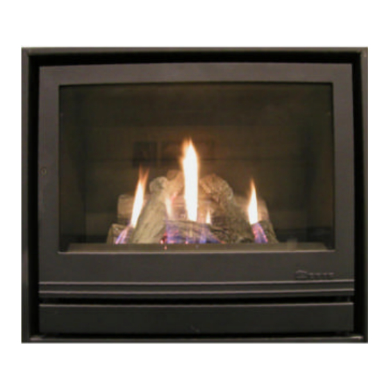
- Page 1 GASHAARD / FOYER A GAZ GAS FIREPLACE / GASOFEN 2530GA(P) INSTALLATIEVOORSCHRIFTEN EN GEBRUIKSAANWIJZING INSTALLATION ET MODE D’EMPLOI INSTALLATION INSTRUCTIONS AND OPERATING MANUAL EINBAUANLEITUNG UND GEBRAUCHSANWEISUNG - 1 - 2530GA(P) 03.27603.000...
-
Page 2: Table Des Matières
Inhoudsopgave (BE, NL) Voorwoord ........................... 4 1. Inleiding ........................4 2. Veiligheid ........................4 3. Algemene voorschriften ....................5 3.1. De schoorsteen ..................... 6 3.2. Ventilatie van het lokaal ..................7 4. Installatie ........................7 4.1. Voorbereiding ....................... 7 4.2. Plaatsing van het toestel ..................7 4.3. - Page 3 Table of contents (GB, IE) page Foreword ..........................30 1. Introduction .........................30 2. Safety ..........................30 3. General prescriptions ....................31 3.1. The chimney ......................32 3.2. Ventilation ......................33 4. Installation ........................33 4.1. Preparation ......................33 4.2. Installing of the appliance .................33 4.3. Connection to the chimney ................33 4.4.
-
Page 4: Voorwoord
Voorwoord Bij deze haard ontvangt u deze installatievoorschriften en gebruiksaanwijzing. U vindt er naast instructies voor het plaatsen en informatie over het gebruik, ook adviezen omtrent veiligheid en onderhoud. Lees dit boekje zorgvuldig, vooraleer met de plaatsing aan te vatten en het toestel in gebruik te nemen. -
Page 5: Algemene Voorschriften
het binnenwerk van de haard bevindt, de gelegenheid krijgt tot verdampen, en de hittebestendige lak de kans heeft om uit te harden. Witte aanslag op het glas en op het binnenwerk is mogelijk tijdens deze eerste periode. Met een doek is deze aanslag eenvoudig te verwijderen van zodra het toestel afgekoeld is. -
Page 6: De Schoorsteen
3.1. De schoorsteen De schoorsteen (het rookkanaal) heeft een dubbele functie : • Het aanzuigen van de lucht vanuit de kamer, nodig voor de verbranding van de brandstof in de kachel of open haard. • Het afvoeren van de verbrandingsgassen door thermische en natuurlijke trek. De thermische trek ontstaat door het warmteverschil tussen de lucht in en buiten het rookkanaal. -
Page 7: Ventilatie Van Het Lokaal
Aansluiting op het schoorsteenkanaal De aansluitkraag moet hermetisch met de schoorsteen worden verbonden. Gebruik eventueel het “Dovre bajonet”-systeem (in optie): Monteer eerst op de schroeven op de topplaat van het toestel een moer, een rondel en dan weer een moer (links en rechts van de aansluitkraag). Onde r deze rondellen komt later de sleutel vast zitten. -
Page 8: Gasaansluiting
4.4. Gasaansluiting De aansluiting op de gasleiding gebeurt aan de rechterkant. Controleer of de gassoort en de gasdruk ter plaatse overeenkomen met de aanduiding op het typeplaatje. In de gastoevoerleiding moet een gekeurde gaskraan zo dicht mogelijk bij het toestel en steeds bereikbaar worden gemonteerd. De aansluiting dient spanningsvrij te geschieden. -
Page 9: Plaatsing Van De Imitatie Houtblokken
4.6. Plaatsing van de imitatie houtblokken 4.6.1. Positionering van de brander Indien nog niet gebeurd, neem eerst en vooral de doos met de imitatiehoutblokken uit de ver- brandingskamer. Let op!! De blokken zijn breekbaar, behandel ze voorzichtig. Ga dan na of de brander correct is gepositioneerd en niet bewogen is door trans- port. -
Page 10: Installatie Van De Afstandsbediening (Optie)
4.7. Installatie van de afstandsbediening (optie) De volledige afstandsbedieningmodule bevat een handset (zender), een ontvange r, een aandrijfmotor, een microswitch (versie met thermostaat) en de nodige bekabeling. Het systeem werkt op batterijen en vereist geen uitwendige stroombron. De batterijen (1 x 9V blok voor de handset, 4 x 1.5V AA voor de ontvanger) dienen apart te worden voorzien. -
Page 11: Gebruik
Gebruik 5.1. Aansteken gasregelblok bevindt zich achter onderste deur. De waakvlam bevindt zich net voor de hoofd- brander, en is zichtbaar achter de schermplaat onderaan achter het glas. • Open gasafsluitkraan gasleiding naar het toestel is gemonteerd. • Draai knop A richting ontstekingspositie (1 --> 2) tot je niet verder kunt. •... -
Page 12: Gebruik Van De Afstandsbediening (Optie)
5.4. Gebruik van de afstandsbediening (optie) Indien een afstandsbedieningsmodule is geïnstalleerd, kan de werking van knop B (in- en uitschakelen van de hoofdbrander, regeling van de vlamhoogte) eveneens bediend worden door gebruik te maken van de handset. De afstandsbediening werkt met ultrasoongeluiden. Het is niet noodzakelijk met de handset naar het toestel te richten om het te bedienen. - Page 13 • Bevestig door nogmaals TIMER in te drukken. • Indien slechts 1 verwarmingsperiode gewenst is, geef dan voor P2ã en voor P2» dezelfde tijd in. Manuele mode (MAN op display) - vlamhoogte wordt manueel geregeld • Knop “ p” : knop B draait naar links, debiet verhoogt, vlammen worden groter. •...
-
Page 14: Bediening Van De Ventilator
• In zeldzame gevallen kan knop B van de gasblok geblokkeerd geraken in een van zijn eindpunten. Dit wordt opgelost door hem met de hand uit deze stand te draaien. 5.5. Bediening van de ventilator De ingebouwde ventilator zal automatisch inschakelen van zodra de temperatuur in het toestel begint op te lopen. - Page 15 Toegang tot de belangrijkste componenten • Met behulp van een schroevendraaier kan de de glasdeur geopend worden. • Schroef de afde kplaat onderaan vooraan de verbrandingskamer los (1 schroef, onderaan in het midden) en verwijder ze. De waakvlam is bereikbaar voor herstelling of onderhoud. •...
-
Page 16: Storingen En Oplossingen
Storingen en oplossingen probleem mogelijke oorzaak mogelijke oplossing (*) = ingreep door installateur laten doen hoogspanningskabel los aansluiting nazien kortsluiting van hoogspanningskabel kortsluiting verhelpen bougie gebroken bougie vervangen (*) piëzo-ontsteking defect piëzo vervangen (*) geen gas gastoevoer openen geduld hebben, tot de lucht volledig lucht in leidingen door het gas is uitgeduwd ontspanner juist instellen of de gas-... -
Page 17: Préface
Préface Le foyer vous est fourni avec les notices d'installation et mode d'emploi ci-joints. Outre des instructions pour le placement et des informations sur l'utilisation du foyer, vous y trouverez également des conseils en matière de sécurité et d'entretien. Lisez attentivement ces notices avant de procéder à l'installation et de mettre l'appareil en service. -
Page 18: Prescriptions Générales
et sur les parois intérieures durant cette première période. Ce dépôt s'enlève facile- ment à l'aide d'un chiffon, dès que l'appareil est refroidi. Comme un foyer est une source de chaleur qui crée une circulation de l'air dans la chambre, il importe que vous n'allumiez pas le foyer juste après avoir fait des trans- formations dan votre habitation. -
Page 19: La Cheminée
3.1. La cheminée La cheminée (conduit de fumée) a une double fonction : • L’aspiration de l’air du local, nécessaire à la combustion du combustible dans le foyer. • L’évacuation vers l’extérieur des produits de combustion ou des fumées qui se forment dans le poêle ou le foyer. -
Page 20: Ventilation Du Local
Raccordement au conduit de cheminée Le collier de raccordement de l’appareil doit être relié à la cheminée de façon étan- che, au moyen d’une buselure résistante à la corrosion. Le Dovre “baîonnette- système”: Vissez d’abord sur les tiges filettées un écrou, une rondelle et encore un écrou (à... -
Page 21: Raccordement Au Gaz
4.4. Raccordement au gaz Le raccordement à la conduite de gaz s'effectue du côté droit. Contrôlez si le type de gaz et la pression du gaz sur place correspondent aux indications mentionnées sur la plaque d'identification de l'appareil. Dans la conduite d'arrivée du gaz, un robinet de gaz agréé doit être monté le plus près possible de l'appareil et être toujours accessible. -
Page 22: Placement Des Büches D'imitation
4.6. Placement des bûches d'imitation 3.6.1. Positionnement du brûleur Si cela n'a pas encore été fait, sortez avant toute chose la boîte de bûches d'imitation de la chambre de combustion. Attention !! Les bûches sont fragiles, manipu- lez-les avec précaution. Vérifiez ensuite si le brûleur est correctement positionné... -
Page 23: Installation De La Commande À Distance (Option)
4.7. Installation de la commande à distance (option) Le module de commande à distance (disponible en option) comporte un combiné émetteur, un récepteur, un moteur, un microswitch (version à thermostat) et le c â- blage électrique. Le système fonctionne sur piles et ne demande aucune source de courant extérieure. -
Page 24: Mode D'emploi
Mode d‘emploi 5.1. Allumage Le bloc de réglage du gaz se trouve à droite en- dessous du foyer (voir croquis). La veilleuse se trouve juste devant le brûleur principal et est visible derrière l'écran de protection en-dessous derrière le verre. •... -
Page 25: Utilisation De La Commande À Distance (Option)
5.4. Utilisation de la commande à distance (option) Si le module de commande à distance est installé, le bouton B du bloc gaz (mise en route et arrêt du brûleur principal, réglage de la hauteur des flammes) peut être commandé également depuis le combiné émetteur. La commande à... - Page 26 Mode manuel (MAN sur écran) - réglage manuel de la hauteur de flamme • Bouton “p” : bouton B tourne vers la gauche, les flammes grandissent. • Bouton “q” : bouton B tourne vers la droite, les flammes deviennent plus petites. Le symbole “émission”...
-
Page 27: Ventilateur
5.5. Ventilateur Le ventilateur incorporé se met automatiquement en route dès que la température à l'intérieur de l'appareil commence à s'élever. De la même façon, à l'extinction où à la mise en veilleuse de l'appareil, le ventilateur restera en fonctionnement jusqu'à ce que toute la chaleur encore présente dans l'appareil sera débitée. - Page 28 Accès aux composants principaux • Ouvrez la porte vitrée. Dévissez d‘abord la petite vis de bloqage de la poignée. • Retirez éventue llemant le pare -bûches. • La veilleuse est visible à l‘avant de la chambre de combustion, et est facilement accessible pour entretien et/ou réparation.
-
Page 29: Pannes Possibles Et Remèdes
Pannes possibles et remèdes défaut cause possible solution possible (*) = intervention par l’installateur Câble de haute tension mal fixé Fixer le câble Mise à la masse du câble haute tension Réparer la mise à la masse bougie cassée Remplacer la bougie (*) Piézo défectueux Remplacer le piézo (*) Pas de gaz... -
Page 30: Foreword
Foreword These installation directions and instructions for use accompany this appliance. Also included with this manual is a section on advice concerning safety and maintenance. Read this booklet carefully before attempting to install or use the unit. Save this booklet for passing on to subsequent users. Introduction This heater is designed to be installed in a living room and to be hermetically con- nected to a flue (chimney). -
Page 31: General Prescriptions
may appear on the glass and on the interior during this initial period. This residue can be easily removed with a cloth as soon as the unit has cooled off. Because a fireplace is a heat source that provides for air circulation in the room, it is important that you do not burn the fireplace soon after renovating. -
Page 32: The Chimney
3.1. The chimney The chimney (the flue) has a double function: • It draws air, that is necessary for good combustion, into the stove. • It functions as an exhaust pipe for combustion gases via thermal or natural draught. Thermal draught is caused by the difference in heat between the air in- and outside the flue. -
Page 33: Ventilation
The connection collar must be hermetically connected to the chimney by means of a corrosion resistant pipe. You might want to use the 'Dovre bayonet' system (optional). First attach a nut, a washer, and then another nut to the screws on the top plate of the appliance (to the left and to the right of the connection collar). -
Page 34: Gas Connection
4.4. Gas connection Connection to the gas line is made on the right-hand side. Check that the type of gas and the gas pressure correspond with the specifications on the specification plate. An approved gas cock must be installed in the gas line as close as possible to the unit in a place that is always accessible. -
Page 35: Placing Of The Imitation Logd And Ashes
4.6. Placing the imitation logd and ashes 4.6.1. Positioning of the burner If it has not yet been done, first remove the box containing the imitation logs from the combus- tion chamber. Watch out!! The logs are fragile. Handle them carefully. -
Page 36: Installing The Remote Control (Option)
4.7. Installing the remote control (option) The complete remote control unit comprises a handset (emitter), a receiver, a motor, a micro switch (only for the thermostat version) and the electric connection cable. The system works on batteries and does not require any external power source. The batteries themselves (1 x 9V block for the handset, 4 x 1.5V AA for the receiver) should be supplied separately. -
Page 37: Operating Instructions
Operating instructions 5.1. Lighting The gas regulating control is located at the bot- tom of the fireplace, behind the hinged panel in the decorative frame (see figure). The pilot light is located just in front of the main burner, and is visible behind the glass. •... -
Page 38: Operating The Remote Control (Option)
5.4. Operating the remote control (option) If the remote control unit is installed, the operation of knob B can also be controlled using the handset of the remote control. The remote control works by ultrasound. It is not necessary to direct the handset towards the unit to operate it. - Page 39 Manual Mode (MAN in display) for Manual Flame Height Adjustment • Press p to turn on the fire (main burner) or to increase flame height. • Press q to decrease flame or to turn down to pilot. • To incrementally increase or decrease the flame height lightly tap either p or q The “send“...
-
Page 40: Operating The Fan
Minor paint damage can be touched up with spray paint and enamelled surface damage can be touched up with coloured repair kits. Both products are available from your Dovre Dealer. During the first use after paint spraying your unit may give off a slight odour. This will quickly disappear. - Page 41 Access to the most important components • Open the front door. Unscrew the little locking bolt of the hinge first. • Remove the loose log retainer. • The pilot flame is visible in front of the combustion chamber and is very easily accessible.
-
Page 42: Troubleshooting
Troubleshooting symptom possible cause possible remedy (*) = must be carried out by qualified engineer High tension lead loose Check connection (*) Establish where spark is occuring and insulate HT lead shorting out on burner body or re-route lead accordingly (*) Electrode broken Replace electrode (*) Faulty piezo-igniter... -
Page 43: Vorwort
Vorwort Zusammen diesem Ofen erhalten Einbauanleitung Gebrauchsanweisung. Neben Informationen über Installation und Betrieb finden Sie hierin auch Tipps im Zusammenhang mit Sicherheit und Wartung. Bitte lesen Sie dieses Heft sorgfältig durc h, bevor Sie mit dem Einbau und der Inbetriebnahme des Geräts beginnen. Heben Sie es bitte auch für den Fall gut auf, dass ein z ukünftiger Benutzer sich zurechtfinden kann. -
Page 44: Allgemeine Richtlinien
Innenseite des Ofens aufgetragene Fett kann auf diese Art und Weise verdampfen hitzebeständige Lack kann aushärten. Während dieser ersten Inbetriebnahme kann auf dem Glas und an der Innenseite ein weißer Ansatz auftreten. Sobald das Gerät abgekühlt ist, kann dieser mit einem Tuch einfach entfernt werden. -
Page 45: Der Schorstein
3.1. Der Schornstein Der Schornstein (der Rauchkanal) hat eine zweifache Funktion: • Das Ansaugen der Luft aus dem Zimmer, was für die Verbrennung des Brennstoffes im Ofen oder Kamin nötig ist. • Das Abführen der Verbrennungsgase durch thermischen und natürlic hen Zug. Der thermische Zug entsteht durch den Wärmeunterschied zwischen der Luft im und außerhalb des Rauchkanals. -
Page 46: Lüftung Des Räumes
Anschluss zum Schornsteinkanal Der Anschlusskragen muss hermetisch mit dem Schornstein über ein korrosions-beständiges Verbindungsstück verbunden werden. Benutzen Sie eventuell das "Dovre bajonet"-System (Option): montieren Sie zuerst auf die Schrauben der Oberplat- te des Geräts eine Mutter, eine Unterlegscheibe und wieder eine Mutter (links und rechts der Anschlußmuffe). -
Page 47: Gasanschluss
Das Anschlußrohr D. 100 mm, eventuell Flexrohr, wird auf die gußeiserne Muffe montiert mittels eines Klemmrings mit dazwischen dem Schlüßel. Mit einer minima- len Einbauhöhe kann man, nachdem das Gerät in die Nische geschoben worden ist, mit dem Schlüßel das Rohr in die Anschlußmuffe einbringen mittels eines langen Schraubenziehers oder einer Stange. -
Page 48: Einbau Der Holzscheitimitate
4.6. Einbau der Holzscheitimitate 4.6.1. Positionierung des Brenners Falls noch nicht geschehen, nehmen Sie zuerst die Dose Holzscheitimitaten Brennraum. Achtung! Die Blöcke sind zerbrechlich, behandeln Sie sie mit Vorsicht. Überprüfen Sie danach, ob der Brenner korrekt positioniert und während des Transports nicht verrutscht ist. Der Brenner ruht lose auf dem Boden des Brennraums, lehnt von hinten auf dem Halter der Düse und vorne links und rechts auf zwei Füßchen. -
Page 49: Einbau Der Fernbedienung (Option)
4.7. Einbau der Fernbedienung Das vollständige Fernbedienungmodul umfasst einen Handset (Sender), einen Empfänger, einen Antriebsmotor, einen Mikroschalter (Version mit Thermostat) und die erforderliche Bekabelung. Das System arbeitet mit Batterien und benötigt keine externe Stromquelle. Die Batterien (1 x 9V Block für das Handset, 4 x 1,5V AA für den Empfänger) sind separat einzubringen. -
Page 50: Betrieb
Betrieb 5.1. Anmachen Der Gasregelblock befindet sich rechts unten am Ofen (s. Abbildung). Die Sparflamme befindet sich kurz vor dem Hauptbrenner, sichtbar hinter der Schutzplatte unten. • Öffnen Sie den Gasabschlusshahn, der sich in der Gasleitung befindet, die zum Gerät führt. •... -
Page 51: Fernbedienung (Option)
5.4. Fernbedienung (Option) Wenn die Fernbedienungsmodul installiert ist, kann die Funktion von Knopf B auch über den Handset de r Fernbedienung geregelt werden. Die Fernbedienung arbeitet mit Ultraschall. Es ist daher nicht erforderlich, das Handset zum Ofen hin zu richten, um diesen zu bedienen. 5.4.1. - Page 52 Temperaturregelung (AUTO) AUTO kurz drücken. Im Display erscheint kurz die eingestellte Temperatur, anschliessend die Raumtemperatur. Timer (TIMER) Im Timermodus erfolgt in den Ein-Zeiten eine Temperaturregelung wie im AUTO- modus, in den Aus-Zeiten schaltet der Motor das Gerät auf Zündflamme. Während Aus-Zeiten findet keine...
-
Page 53: Bedienung Des Ventilators
5.5. Bedienung des Ventilators Der eingebaute Ventilator wird automatisch eingeschaltet, sobald die Temperatur im Gerät anfängt zu steigen. Beim Ausschalten des Geräts dreht der Ventilator weiter, bis alle in dem Gerät noch anwesende Luft abgeführt worden ist. Mit dem Wählschalter (rechts hinter der unteren Schalttafel) kann vom Benutzer eine hohe oder niedrige Geschwindigkeit gewählt werden. - Page 54 Zugang zu den wichtigsten Komponenten • Öffnen Sie die Tür. • Entfernen Sie die Schutzplatte voran der Verbrennungskammer. • Die Zündflamme ist ganz sichtbar, und ist ohne Schwierigkeiten für Reparatur- bzw. Pflegezwecke erreichbar. • Entfernen Sie die Imitationskohlen oder Holzscheite und den Spiegel. •...
-
Page 55: Diagnoseplan
Diagnoseplan Problem Mögliche Ursache Mögliche Lösung (*) = Eingriff vom Installateur ausführen lassen Hochspannungskabel los Anschluss überprüfen (*) Kurzschluss in Hochspannungskabel Kurzschluss beheben (*) Zündkerze gebrochen Kerze ersetzen (*) Piezo-Zündung defekt Piezo-Zündung ersetzen (*) Kein Gas Gazszufuhr aufdrehen Warten, bis die Luft von dem Gas verdrängt Luft in Leitungen worden ist. - Page 56 - 56 - 2530GA(P) 03.27603.000...
- Page 57 Bijlage 2 : Afmetingen Annexe 2 : Dimensions Annex 2 Dimensions Anlage 2 : Abmessungen - 57 - 2530GA(P) 03.27603.000...
- Page 58 - 58 - 2530GA(P) 03.27603.000...
- Page 59 - 59 - 2530GA(P) 03.27603.000...
- Page 60 Im Rahmen kontinuerlicher Produktverbesserung, können Specifikationen des geliefe rtes Produktes von den Beschreibungen in dieser Broschure abweichen. DOVRE N.V. Tel : +32 (0) 14 65 91 91 Nijverheidsstraat 18 Fax : +32 (0) 14 65 90 09 B-2381 Weelde E-mail : info@dovre.be ___________________________________________________________ 03.27603.000 0420 - 60 - 2530GA(P) 03.27603.000...