Toro Power Max 726 Manuel De L'utilisateur
Snow thrower
Table des Matières
Les langues disponibles
Les langues disponibles
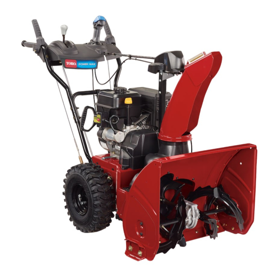
Power Max 726/826 OE Snowthrower
Model No. 37771-Serial No. 313000001 and Up
Model No. 37772-Serial No. 313000001 and Up
Introduction
This machine is intended to be used by residential
homeowners or professional, hired operators. It is
designed for removing snow from paved surfaces, such
as driveways and sidewalks, and other surfaces for
traffic on residential or commercial properties. It is not
designed for removing materials other than snow, nor is
a model with a pivoting scraper designed for clearing off
gravel surfaces.
Read this information carefully to learn how to operate and
maintain your machine properly and to avoid injury and
machine damage. You are responsible for operating the
machine properly and safely.
You may contact Toro directly at www.Toro.com for machine
and accessory information, help finding a dealer, or to register
your machine.
Whenever you need service, genuine Toro parts, or additional
information, contact an Authorized Service Dealer or Toro
Customer Service and have the model and serial numbers of
your machine ready. Figure 1 identifies the location of the
model and serial numbers on the machine. Write the numbers
in the space provided.
g018884
1. Model and serial number location
Model No.
Serial No.
This manual identifies potential hazards and has safety
messages identified by the safety alert symbol (Figure 2),
© 2012-The Toro® Company
8111 Lyndale Avenue South
Bloomington, MN 55420
Figure 1
Register at www.Toro.com.
which signals a hazard that may cause serious injury or death
if you do not follow the recommended precautions.
1. Safety alert symbol
This manual uses 2 words to highlight information.
Important calls attention to special mechanical information
and Note emphasizes general information worthy of special
attention.
WARNING
CALIFORNIA
Proposition 65 Warning
The engine exhaust from this product
contains chemicals known to the State of
California to cause cancer, birth defects,
or other reproductive harm.
This spark ignition system complies with Canadian ICES-002.
The enclosed Engine Owner's Manual is supplied for
information regarding the US Environmental Protection
Agency (EPA) and the California Emission Control
Regulation of emission systems, maintenance, and
warranty. Replacements may be ordered through the
engine manufacturer.
Contents
Introduction .................................................................. 1
Training ................................................................. 3
Preparation............................................................. 3
Operation............................................................... 3
Clearing a Clogged Discharge Chute .......................... 4
Maintenance and Storage.......................................... 4
Toro Snowthrower Safety ......................................... 4
Safety and Instructional Decals ................................. 5
Setup ............................................................................ 7
1 Installing the Upper Handle.................................... 8
Original Instructions (EN)
All Rights Reserved *3374-194* A
Printed in the USA
Form No. 3374-194 Rev A
Operator's Manual
Figure 2
Chapitres
Table des Matières

Manuels Connexes pour Toro Power Max 726


Sommaire des Matières pour Toro Power Max 726
- Page 33 Lorsque vous contactez un dépositaire agréé ou le service après-vente Toro pour l'entretien de votre machine, pour CALIFORNIE vous procurer des pièces Toro d'origine ou pour obtenir Proposition 65 - Avertissement des renseignements complémentaires, munissez-vous des numéros de modèle et de série de la machine. Figure 1 indique Les gaz d'échappement de cette machine...
- Page 34 Utilisation............... 4 Pour déboucher l'éjecteur ......... 4 Entretien et remisage ..........4 Sécurité des souffleuses à neige Toro ......5 Autocollants de sécurité et d'instruction ..... 6 Mise en service .............. 8 1 Montage de la partie supérieure du guidon ....9 2 Montage de la tringlerie de commande de déplacement............
-
Page 35: Avant L'utilisation
Sécurité Avant l 'utilisation Prudence : un usage incorrect peut entraîner la perte de doigts, de mains Lisez et assimilez le contenu de ce manuel avant d 'utiliser la déneigeuse. ou de pieds. Une turbine rapide est Familiarisez-vous avec toutes les commandes située près de et apprenez à... -
Page 36: Utilisation
• toujours les bidons sur le sol, à l'écart du véhicule, Ne faites pas tourner le moteur à l'intérieur, sauf pour avant de les remplir. faire démarrer la machine et la rentrer ou la sortir du bâtiment. Ouvrez les portes vers l'extérieur pour aérer, –... -
Page 37: Sécurité Des Souffleuses À Neige Toro
• N'achetez que des pièces et des accessoires Toro d'origine. Sécurité des souffleuses à neige Toro La liste suivante contient des instructions de sécurité... -
Page 38: Autocollants De Sécurité Et D'instruction
Autocollants de sécurité et d'instruction Important: Les autocollants de sécurité et d'instruction sont placés près des endroits potentiellement dangereux. Remplacez les autocollants endommagés. 121–6817 1. Risque de coupure/mutilation par la turbine et la vis sans fin – Tenez les spectateurs à bonne distance de la souffleuse à... - Page 39 Réf. Briggs & Stratton 273676 1. Arrêt 3. Haut régime 2. Bas régime Réf. Briggs & Stratton 277588 1. Amorceur 3. Clé de contact sortie Réf. Briggs & Stratton 275949 (Moteur – Arrêt) 1. Starter fermé (starter 2. Starter ouvert (marche) 2.
-
Page 40: Mise En Service
Mise en service Pièces détachées Reportez-vous au tableau ci-dessous pour vérifier si toutes les pièces ont été expédiées. Procédure Description Qté Utilisation Boulons de guidon Rondelles bombées Montez la partie supérieure du guidon. Contre-écrous Montez la tringlerie de commande de –... -
Page 41: Montage De La Partie Supérieure Du Guidon
l'extrémité dans le bras de liaison inférieur de sorte que l'extrémité courbe de la tige de commande de vitesse soit dirigée vers l'arrière (Figure 4). Montage de la partie supérieure du guidon Pièces nécessaires pour cette opération: Boulons de guidon Rondelles bombées Contre-écrous g019004... -
Page 42: Montage De L'éjecteur
Figure 6 6. Soulevez la tige de commande de vitesse et insérez le tourillon dans le trou du levier sélecteur de vitesses (Figure 5). Remarque: Si le tourillon ne rentre pas dans le trou lorsque vous soulevez la tige de commande de vitesses, g01901 1 tournez-le en haut ou en bas sur la tige jusqu'à... -
Page 43: Plein D'huile Moteur
Figure 11 1. Serre-câble 2. Câble de déflecteur Figure 9 7. Maintenez le déclencheur bleu enfoncé et faites 1. Tige courte 2. Tige longue effectuer un cercle au Quick Stick pour vérifier que l'éjecteur et le déflecteur fonctionnent correctement. 4. Insérez l'avant de la tige dans l'ouverture au dos du couvercle du secteur denté... -
Page 44: Contrôle De La Pression Des Pneus
Capacités d'huile moteur (cont'd.) Modèle Capacité d'huile moteur 37771 0,53 à 0,59 l (18 à 20 oz) Contrôle de la lame racleuse 37772 et des patins 1. Retirez la jauge et versez de l'huile lentement dans le goulot de remplissage pour faire monter le niveau de liquide jusqu'au repère du plein (Full) sur la jauge. -
Page 45: Vue D'ensemble Du Produit
Vue d'ensemble du produit Figure 14 La machine devrait reculer. Si ce n'est pas le cas, ou si la machine se déplace en avant, procédez comme suit : A. Relâchez le levier de commande de déplacement et coupez le moteur. B. -
Page 46: Utilisation
Pour que la machine se propulse automatiquement, insérez la goupille de l'essieu dans les trous des moyeux et les trous de l'essieu (Figure 19). g019014 Figure 19 g018888 Figure 16 Remplissage du réservoir de 1. Starter 5. Démarreur à lanceur carburant 2. -
Page 47: Démarrage Du Moteur
Démarrage du moteur Important: Pour réduire les problèmes de démarrage, ajoutez un stabilisateur à chaque plein et utilisez de 1. Contrôlez le niveau d'huile moteur (voir Contrôle du l'essence stockée depuis moins d'un mois. N'ajoutez niveau d'huile moteur à la section Entretien). pas d'huile à... - Page 48 (5 secondes maximum, puis attendez une minute avant de recommencer). Si le moteur ne démarre toujours pas, portez la machine chez un réparateur Toro agréé pour la faire réviser. 8. Débranchez le cordon d'alimentation, d'abord de la prise puis de la machine (démarrage électrique seulement).
-
Page 49: Arrêt Du Moteur
Fonctionnement de la PRUDENCE transmission aux roues Si vous laissez la machine branchée à une prise secteur, elle risque d'être mise en marche accidentellement, et de blesser quelqu'un ou PRUDENCE de causer des dommages matériels. Si la transmission n'est pas réglée correctement, la machine risque de se déplacer dans la direction Débranchez le cordon d'alimentation quand opposée à... -
Page 50: Utilisation De La Commande De La Vis Sans Fin/Turbine
Si l'éjecteur ne se bloque pas en position quand vous blesser d'autres personnes. relâchez le déclencheur, reportez-vous à la section Réglage N'utilisez pas la machine. Portez-la chez un du cliquet de verrouillage de l'éjecteur. réparateur Toro agréé pour la faire réviser. -
Page 51: Déplacement Du Déflecteur
Déplacement du déflecteur certaines commandes ou pièces sont difficiles à utiliser, mettez le moteur en marche et laissez-le tourner quelques Maintenez le déclencheur bleu enfoncé et déplacez le Quick minutes. Stick vers l'avant pour abaisser le déflecteur, ou vers l'arrière •... -
Page 52: Entretien
échéant. Important: Vous trouverez d'autres informations sur l'entretien et la révision de la machine sur le site www.Toro.com. Important: Reportez-vous au manuel d'utilisation du moteur pour toutes procédures d'entretien supplémentaires. -
Page 53: Contrôle Et Réglage Des Patins Et De La Lame Racleuse
Remarque: Si le sol est fissuré, inégal ou irrégulier, dessous du repère "Add" sur la jauge (voir Plein d'huile du carter moteur). réglez les patins de manière à élever la lame racleuse. Sur le gravier, réglez les patins plus bas pour éviter que la machine ne ramasse des cailloux. -
Page 54: Contrôle Et Réglage Du Câble De Commande De La Vis Sans Fin/Turbine
3. Desserrez ou serrez le tendeur afin de régler la longueur du ressort à 7 cm (2,75 pouces) (Figure 40). g019048 g019047 Figure 38 Figure 40 3. Ressort 1. Écrou de blocage 3. Ressort 2. Tendeur 4. 5,5 cm (2,18") 1. -
Page 55: Vidange Et Remplacement De L'huile Moteur
Vidange et remplacement de l'huile moteur Périodicité des entretiens: Après les 5 premières heures de fonctionnement—Vidangez et remplacez l'huile moteur. Toutes les 25 heures/Une fois par an (la première échéance prévalant)—Vidangez et remplacez l'huile moteur. Dans la mesure du possible, faites tourner le moteur juste Figure 41 avant la vidange pour réchauffer l'huile, afin de faciliter son écoulement et d'entraîner plus d'impuretés. -
Page 56: Graissage De L'arbre Hexagonal
3. Vidangez l'huile. Remarque: Débarrassez-vous correctement de l'huile usagée en la déposant dans un centre de recyclage agréé. 4. Remettez le bouchon de vidange. 5. Remplissez le carter moteur (voir Plein d'huile du carter moteur). Graissage de l'arbre hexagonal Périodicité des entretiens: Une fois par an—Graissez g019019 l'arbre hexagonal. -
Page 57: Réglage Du Cliquet De Verrouillage De L'éjecteur
1. Enlevez la commande de starter et la clé de contact 9. Fixez le support avec la vis à oreilles retirée à l'étape 4. (Figure 46). 10. Le flexible de la poire d'amorceur et le câble d'allumage 2. Enlevez les 2 vis qui fixent le capot anti-neige à la doivent être connectés et écartés du support du machine (Figure 46). -
Page 58: Remisage
Remisage 3. Branchez la bougie. 4. Effectuez les procédures d'entretien annuelle qui sont indiquées dans le Programme d'entretien recommandé. ATTENTION • Les vapeurs d'essence sont explosives. • Ne conservez pas l'essence plus d'un mois. • Ne remisez pas la machine dans un local fermé où... -
Page 59: Dépistage Des Défauts
Dépistage des défauts Mesure corrective Problème Cause possible Le démarreur électrique ne fonctionne 1. Le cordon d'alimentation n'est pas 1. Raccordez le cordon d'alimentation à pas (modèles à démarrage électrique branché à la prise secteur ou à la la prise et/ou la machine. seulement). - Page 60 7. La courroie de la vis sans fin/turbine 7. Remplacez la courroie d'entraînement est usée ou cassée. de la vis sans fin/turbine. Consultez le site www.Toro.com pour de plus amples informations d'entretien ou portez la machine chez un réparateur agréé.
-
Page 61: Remarques
Remarques:... -
Page 62: Déclaration De Garantie De Conformité À La Réglementation Sur Le Contrôle Des Émissions
En cas de défaillance de la pièce pendant la période de garantie, cette dernière sera réparée ou remplacée par The Toro Company. Toute pièce ainsi réparée ou remplacée sous garantie sera couverte pour la durée de garantie restante. - Page 63 10. L'utilisation de pièces ajoutées ou modifiées et non approuvées par The Toro Company est interdite. L'utilisation par l'acheteur de pièces ajoutées ou modifiées et non agréées constituera un motif de rejet d'une réclamation au titre de la garantie. The Toro Company ne sera pas tenue de couvrir les pannes des pièces sous garantie causées par l'utilisation de pièces ajoutées ou modifiées et non agréées.
-
Page 64: La Garantie Intégrale Toro
Autres pays que les États-Unis et le Canada Pour les produits Toro exportés des États-Unis ou du Canada, demandez à votre distributeur (dépositaire) Toro la police de garantie applicable dans votre pays, région ou état. Si, pour une raison quelconque, vous n'êtes pas satisfait des services de votre distributeur, ou si vous avez du mal à vous procurer les informations de garantie, adressez-vous à...