Publicité

Les langues disponibles
  • FR

Les langues disponibles

  • FRANÇAIS, page 25

Liens rapides

ISTRUZIONI PER L'USO DEL TELAIO
FRAME ASSEMBLY INSTRUCTIONS
BEDIENUNGSANLEITUNG FUER DEN RAHMEN
NOTICE D'UTILISATION DU CADRE
INSTRUCCIONES PARA EL USO DEL CUADRO
GEBRUIKSAANWIJZING VOOR FRAME
IT
EN
DE
FR
ES
NL

Publicité

Table des Matières
loading

Sommaire des Matières pour Elite QUB0

  • Page 1 ISTRUZIONI PER L'USO DEL TELAIO FRAME ASSEMBLY INSTRUCTIONS BEDIENUNGSANLEITUNG FUER DEN RAHMEN NOTICE D’UTILISATION DU CADRE INSTRUCCIONES PARA EL USO DEL CUADRO GEBRUIKSAANWIJZING VOOR FRAME...
  • Page 2 • INTRODUZIONE • MONTAGGIO UNITÁ • INSTALLAZIONE DELLA BICICLETTA • RIMOZIONE DELLA BICICLETTA • MONTAGGIO PIEDI DI LIVELLAMENTO • ATTENZIONI • CONSIGLI PER L'UTILIZZO • INTRODUCTION • UNIT ASSEMBLY • FITTING THE BICYCLE • BIKE REMOVAL • LEVELLING FEET ASSEMBLY •...
  • Page 3 • INTRODUCTION • ASSEMBLAGE UNITE • INSTALLATION DE LA BICYCLETTE • ENLÈVEMENT DE LA BICYCLETTE • ASSEMBLAGE DES PIEDS DE NIVELAGE • ATTENTION • CONSEILS POUR L’UTILISATION • INTRODUCCIÓN • MONTAJE UNIDAD • INSTALACIÓN DE LA BICICLETA • CÓMO SACAR LA BICICLETA •...
  • Page 4 Molte grazie per aver acquistato Qubo INTRODUZIONE ATTENZIONE Verificare la presenza di tutti i componenti seguenti: L'unità indicata nella figura d'insieme è puramente indicativa N°1 Telaio Qubo (Rif. A) N°1 Unità (Rif. B) N°1 Sgancio Rapido (Rif. C) N°2 Viteria Unità M6 (D) N°10 Piedini di Livellamento (E)
  • Page 5: Montaggio Unità

    MONTAGGIO UNITÀ ø30 ø45 • Aprire il cavalletto (A) dalla posizione iniziale d’imballo (Fig.1) e posizionarlo su una superficie piana (Fig. 2). • A seconda del tipo di unità andare a fissare completamente le viti M6 (D) (Fig. 5 e Fig.6). Attenzione! Unità...
  • Page 6: Installazione Della Bicicletta

    INSTALLAZIONE DELLA BICICLETTA • Accertarsi che lo sgancio rapido della ruota parallel posteriore della bicicletta sia fissato correttamente. • Posizionare la leva (F) in posizione “open” (Fig.7). • Chiudere la leva (F), facendo attenzione che cominci a comprimere lo sgancio rapido all’inter- no dell’area di lavoro predefinita quella delimitata da 55°...
  • Page 7 l’unità di resistenza (B) allentando le viti (D) di fissaggio dell’unità e bloccarle nella posizione più corretta (Fig.16, Fig.17 e Fig.18). • Se la leva (F) comincia a comprimere lo sgancio rapido nella posizione di lavoro posticipata (Fig. 13), svitare il perno bussola sinistro (G) (Fig. 14) in modo tale che la leva (F) cominci a lavorare all'in- terno dell'area predefinita (quella delimitata da 55°...
  • Page 8: Rimozione Della Bicicletta

    • Spingere la bicicletta verso l’unità di resistenza (B), fino a quando la ruota posteriore arriva a con- tatto con il rullino dell’unità stessa (Fig. 19). • Verificare la stabilità della bicicletta tirando e spingendo il tubo orizzontale del telaio ed agendo sulla sella.
  • Page 9 MONTAGGIO PIEDI DI LIVELLAMENTO • Il telaio Cube (A) ha in dotazione una serie di piedi di livellamento (E) per sopperire ad eventua- li problemi di planarità del pavimento che non permettono ai quattro piedi di appoggiarsi com- • I piedi di livellamento (E) possono essere pletamente e per consentire una perfetta vertica- montati sotto i piedi posteriori (Fig.28 e Fig.29).
  • Page 10 ATTENZIONI • Evitare che persone, bambini o animali possano avvicinarsi al rullo durante l’utilizzo in quanto i componenti in movimento o rotanti del rullo e della bicicletta possono produrre danni in caso di contatto. • Prima di iniziare l'allenamento, posizionare il trainer in un luogo adatto, lontano da oggetti potenzialmente pericolosi (mobili, tavoli, sedie...) in modo da evitare ogni rischio di contatto involon-...
  • Page 11 Thank you for choosing the Qubo INTRODUCTION ATTENTION Check the presence of all the following components: Resistance unit depicted here may vary from production models N°1 Qubo frame (Ref. A) N°1 Unit (Ref. B) N°1 Quick release (Ref. C) N°2 M6 Unit screws (D) N°10 Levelling (equalizing) feet (E)
  • Page 12: Unit Assembly

    UNIT ASSEMBLY ø30 ø45 • Unfold the frame (A) from its packaged position (Fig. 1) and place it on a flat surface (Fig. 2) • Tighten the M6 screws (D) (Fig. 5 and Fig. 6) completely, utilizing the correct holes for the dif- ferent roller diameter options.
  • Page 13: Fitting The Bicycle

    FITTING THE BICYCLE • Make sure the quick release of the bicycle rear parallel wheel is properly fixed. • Turn the lever (F) to the “open” position (Fig. 7). • Close the lever (F), making sure it starts pres- sing the quick release inside the predefined work area;...
  • Page 14 unit left or right as necessary, and re-tighten the bolts (Fig.16, Fig.17 and Fig.18). • If the lever (F) starts pressing the quick release in the delayed work position (Fig. 13), unscrew the left bushing pin (G) (Fig. 14) so that the lever starts working inside the predefined work area (between 55°...
  • Page 15 • Push the bicycle towards the resistance unit until the rear wheel touches the roller (Fig. 19). • Verify the stability of the bike by pushing and pulling the horizontal tube of the frame and the saddle. Should the bike still not appear stable, make sure its quick release and lever are correct- ly positioned, that the lever (F) is in a “closed”...
  • Page 16 LEVELLING FEET ASSEMBLY • The Cube frame (A) comes equipped with level- ling feet (E) to compensate for uneven surfaces that do not allow the four feet to make complete • The levelling feet (E) can be mounted under the contact, and to allow the bike to be perfectly ver- rear feet (Fig.
  • Page 17: Advice On Use

    ATTENTION • Keep people, children and animals away from the roller during use, since the moving and rota- ting parts of the roller and the bicycle can cause damage in case of contact. • Before starting training, position the trainer in a dry place, away from potentially hazardous objects (furniture, tables, chairs, etc.) in order to avoid any risk of inadvertent or accidental contact...
  • Page 18 Wir danken Ihnen für den Kauf des Qubo EINLEITUNG ACHTUNG Überprüfen Sie, dass alle nachstehenden Komponenten vorhanden sind: Die Einheit in der Beschreibung dient nur als Beispiel. N°1 Rahmen Qubo (Bez. A) N°1 Widerstandseinheit (Bez. B) N°1 Schnellspanner (Bez. C) N°2 St.
  • Page 19: Montage Der Einheit

    MONTAGE DER EINHEIT ø30 ø45 • Das Gestell (A) aus der ursprünglichen Verpackungsposition heraus öffnen (Abb. 1) und auf einer ebenen Fläche aufstellen (Abb. 2). • Je nach Typ der Einheit die Schrauben M6 (D) vollständig befestigen (Abb. 5 und Abb. 6). !Achtung! Einheit mit Rolle ø30 •...
  • Page 20: Installierung Des Fahrrads

    INSTALLIERUNG DES FAHRRADS • Sicherstellen, dass der Schnellspanner des parallel Hinterrads korrekt befestigt ist. • Den Hebel (F) in Position “open” stellen (Abb.7). • Den Hebel (F) schließen, wobei Sie darauf achten müssen, dass der Hebel (F) den Schnellspanner schon ab einem Winkel von 55°- 65°...
  • Page 21 Befestigungsschrauben (D) der Einheit gelockert und in der korrekteren Position blockiert werden (Abb. 16, Abb. 17 und Abb. 18). • Wenn der Hebel (F) ) beginnt, den Schnellspanner in der zurückgelegten Arbeitsposition zusam- menzudrücken (Abb. 13), den Stift (C) der linken Buchse aufschrauben (Abb.
  • Page 22 • Das Fahrrad zur Widerstandseinheit hin schie- ben, bis das Hinterrad die Rolle der Einheit selbst berührt (Abb. 19). • Die Stabilität des Fahrrads überprüfen, indem das Oberrohr des Rahmens gezogen und gescho- ben und auf den Sattel eingewirkt wird. Falls sich das Fahrrad als nicht stabil erweisen sollte, sicherstellen, dass die Schnellfreigabe und deren Hebel korrekt positioniert sind, dass der Hebel (F)
  • Page 23 MONTAGE DER AUSNIVELLIERENDEN STÜTZFÜSSE • Mit dem Rahmen Cube (A) wird eine Serie an ausnivellierenden Stützfüßen (E) geliefert, um eventuellen Unebenheiten des Bodens, aufgrund • Die ausnivellierenden Stützfüße (E) können derer die vier Stützfüße nicht vollständig auflie- unter den hinteren Stützfüßen montiert werden gen könnten, auszugleichen und eine perfekte (Abb.
  • Page 24 ACHTUNG! • Vermeiden Sie, dass sich Personen, Kinder oder Tiere während des Gebrauchs dem Rollentrainer nähern können, da die in Bewegung oder Rotation befindlichen Komponenten des Rollentrainers und des Fahrrads im Fall eines Kontakts Schäden bewirken können. • Bei Gebrauch vom Radsimulator auf keinen Fall bremsen, da sonst die Rolle und die Reifen stark beschädigt werden können! •...
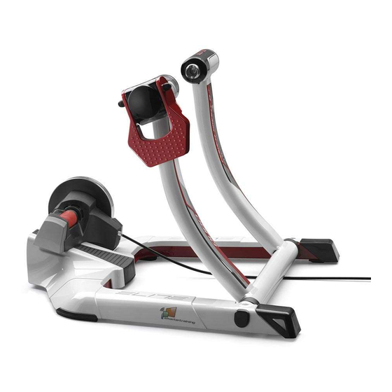
  • Page 25 Merci d’avoir acheté Qubo INTRODUCTION ATTENTION Vérifiez la présence de toutes les pièces suivantes: L’unité indiquée sur le dessin d’ensemble N°1 Châssis Qubo (Réf. A) est purement indicative N°1 Unité (Réf. B) N°1 Déclenchement instantané (Réf. C) N°2 Visserie Unité M6 (D) N°10 Pieds de nivelage (E)
  • Page 26: Assemblage Unite

    ASSEMBLAGE UNITE ø30 ø45 • Ouvrir le support (A) depuis la position initiale d’emballage (Fig.1) et le placer sur une surface plane (Fig. 2). • Selon le type d’unité fixer complètement les vis M6 (D) (Fig. 5 et Fig.6). !Attention! Unité...
  • Page 27: Installation De La Bicyclette

    INSTALLATION DE LA BICYCLETTE • Assurez-vous que le déclenchement instantané de parallel la roue postérieure de la bicyclette soit fixé correc- tement. • Positionnez le levier (F) en position “open” (Fig. 7). • Fermez le levier (F), en veillant à ce qu’il com- mence à...
  • Page 28 l’unité de résistance (B) en dévissant les vis (D) de fixage de l’unité et en les bloquant dans la posi- tion la plus correcte (Fig.16, Fig.17 et Fig.18). • Si le levier (F) commence à comprimer le déclenchement instantané dans la position de travail posticipée (Fig.
  • Page 29: Enlèvement De La Bicyclette

    • Poussez la bicyclette vers l’unité de résistance, jusqu’à ce que la roue postérieure entre en con- tact avec le rouleau de l’unité (Fig. 19). • Vérifier la stabilité du vélo en tirant et poussant le tube horizontal du cadre et en agissant sur la selle.
  • Page 30: Assemblage Des Pieds

    ASSEMBLAGE DES PIEDS DE NIVELAGE • Le cadre Cube (A) est muni d’une série de pieds de nivelage (E) pour faire face à des éventuels • Les pieds de nivelage (E) peuvent être montés problèmes de planéité du sol qui ne permettent sous les pieds postérieurs (Fig.28 et Fig.29).
  • Page 31: Conseils Pour L'utilisation

    ATTENTION • Evitez que des personnes, des enfants ou ani- maux puissent s’approcher du rouleau pendant l’utilisation parce que des éléments en mouve- ment ou tournants du rouleau et du vélo peuvent provoquer des dommages en cas de contact. • Avant de commencer l’entrainement, position- nez le trainer à...
  • Page 32 Le agradecemos que haya escogido Qubo INTRODUCCIÓN ¡ATENCIÓN! Verificar la presencia de todos los componentes siguientes: La unidad indicada en la Figura de conjunto es simplemente indicativa N°1 Bastidor Qubo (Ref. A) N°1 Unità (Ref. B) N°1 Sgancio Rapido (Ref. C) N°2 Conjunto tornillos Unidad M6 (D) N°10 Pies de Nivelado (E)
  • Page 33: Montaje Unidad

    MONTAJE UNIDAD ø30 ø45 • Abrir el soporte (A) de la posición inicial de embalaje (Fig.1) y posicionarlo sobre una superfi- cie plana (Fig. 2). • Según el tipo de unidad, fijar completamente los tornillos M6 (D) (Fig. 5 y Fig.6). ¡Atención! Unidad con rodillo ø30 •...
  • Page 34: Instalación De La Bicicleta

    INSTALACIÓN DE LA BICICLETA • Comprobar que el blocaje rápido de la rueda parallel posterior de la bicicleta esté fijado correctamente. • Posicionar la palanca (F) en posición “open” (Fig. 7). • Cerrar la palanca (F), ponendo atención que empiece a comprimir el blocaje rápido en el inte- rior del área de trabajo predeterminada, la deli- mitada desde 55°...
  • Page 35 mover la unidad de resistencia (B) aflojando los tornillos (D) de sujeción de la unidad y bloquear- los en la posición más correcta (Fig.16, Fig.17 y Fig.18). • Si la palanca (F) empieza a comprimir el blocaje rápido en la posición de trabajo postergada (Fig. 13), destornillar el perno casquillo izquierdo (G) (Fig.
  • Page 36: Cómo Sacar La Bicicleta

    • Empujar la bicicleta hacia la unidad de resisten- cia, hasta que la rueda posterior entre en contacto con el rodillo de la unidad misma (Fig. 19). • Verificar la estabilidad de la bicicleta tirando y empujando el tubo horizontal del cuadro y actuan- do sobre el sillín.
  • Page 37 MONTAJE PIES DE NIVELADO • El cuadro Cube (A) tiene en dotación una serie de pies de nivelado (E) para equilibrar eventuales desniveles del pavimento que no permiten que los • Los pies de nivelado (E) pueden ser montados cuatro pies se apoyen completamente y para debajo de los pies posteriores (Fig.28 y Fig.29).
  • Page 38: Consejos De Uso

    ATENCIÓN • Evita que personas, niños o animales se acer- quen al rodillo durante su uso puesto que los componentes en movimiento o giratorios del rodillo y de la bicicleta pueden provocar daños en caso de contacto. • Antes de empezar el entrenamiento, posicionar el rodillo en un lugar adecuado, lejos de objetos potencialmente peligrosos (muebles, mesas, sil- las...) para así...
  • Page 39 Hartelijk dank voor het kopen van Qubo INLEIDING LET OP! Controleer of alle volgende onderdelen aanwezig zijn: Op de overzichtstekening aangegeven eenheid geldt uitsluitend ter indicatie! N°1 Qubo frame (Ref. A) N°1 Eenheid (Ref. B) N°1 Snelloskoppelmechanisme (Ref. C) N°2 Schroeven M6 eenheid (D) N°10 Stelpoten (E)
  • Page 40: Montage Van De Eenheid

    MONTAGE VAN DE EENHEID ø30 ø45 • Klap de standaard (A) vanuit de oorspronkelijke verpakkingsstand open (Fig. 1) en zet hem op een vlakke ondergrond (Fig. 2). • Afhankelijk van het type eenheid zet u de schroeven M6 (D) volledig vast (Fig. 5 en Fig. 6). !Let op! Eenheid met rol ø...
  • Page 41: Installatie Van De Fiets

    INSTALLATIE VAN DE FIETS • Controleer of het snelloskoppelmechanisme parallel van het achterwiel van de fiets goed bevestigd is. • Zet de hendel (F) in de stand “open” (Fig. 7). • Zet de hendel (F) in de gesloten stand en let erop dat de hendel het snelloskoppelmechanisme in het van tevoren bepaalde werkgebied, binnen 55°...
  • Page 42 (D) van de eenheid los te draaien en ze in de meest geschikte stand aan te draaien (Fig. 16, Fig. 17 en Fig. 18). • Als de hendel (F) het snelloskoppelmechanisme in de latere werkstand begint in te drukken (Fig. 13), moet de linker inbusstift (G) (Fig.
  • Page 43 • Duw de fiets naar de weerstandseenheid toe totdat het achterwiel contact maakt met de rol van de eenheid (Fig. 19). • Controleer of de fiets stabiel staat door aan de horizontale buis van het frame te trekken en er tegen aan te duwen en door op het zadel te drukken.
  • Page 44 MONTAGE VAN DE STELPOTEN • Bij het Cube frame (A) worden een aantal stelpoten (E) geleverd om eventuele problemen voor wat betreft de vlakheid van de vloer waardoor • De stelpoten (E) kunnen onder de achterpoten de vier poten niet volledig op de vloer kunnen gemonteerd worden (Fig.
  • Page 45 OPGELET • Voorkom dat er mensen, kinderen of dieren tijdens het gebruik in de buurt van de trainingsrol kunnen komen omdat de bewegende of roterende onderdelen van de trainingsrol of de fiets in geval van contact schade kunnen veroorzaken. • Alvorens met het trainen te beginnen moet de trainingsrol op een geschikte plaats gezet worden, uit de buurt van voorwerpen die gevaarlijk kunnen zijn (meubels, tafels, stoelen enz.) om elk risico...
  • Page 46 NOTES...
  • Page 47 NOTES...
  • Page 48 ELITE srl - 35014 Fontaniva (PD) - ITALY - Fax +39 049 594 0064 - e-mail: contatto@elite-it.com...

Table des Matières