
Manuels Connexes pour geo-FENNEL FL 300HV-G EasyGRADE


Sommaire des Matières pour geo-FENNEL FL 300HV-G EasyGRADE
- Page 1 DE | EN | FR FL 300HV-G EasyGRADE BEDIENUNGSANLEITUNG USER MANUAL MODE D‘EMPLOI www.geo-fennel.de www.geo-fennel.com www.geo-fennel.fr...
- Page 2 Sehr geehrter Kunde, vielen Dank für das Vertrauen, welches Sie uns beim Erwerb Ihres neuen geo-FENNEL-Gerätes ent- gegengebracht haben. Dieses hochwertige Qualitätsprodukt wurde mit größter Sorgfalt produziert und qualitätsgeprüft. Die beigefügte Anleitung wird Ihnen helfen, das Gerät sachgemäß zu bedienen. Bitte lesen Sie ins- besondere auch die Sicherheitshinweise vor der Inbetriebnahme aufmerksam durch.
- Page 3 FUNKTIONEN · 1-Achs-Neigungslaser horizontal mit Vertikalfunktion ALLGEMEIN HORIZONTAL · Automatische TILT-Funktion · Selbstnivellierend · Numerische Neigungseinstellung der X- · VWS-Funktion (Vibrations-Wind-Schutz) Achse von 0,1% bis 6,9% in 0,1%-Schritten · 90° Lotstrahl · Staub-/Wasserschutz IP 66 · Manuelle Neigung der Y-Achse mit Fern- bedienung VERTIKAL ·...
- Page 4 STROMVERSORGUNG Der Laser ist mit einem Li-Ion-Akkupack ausgestattet. Alternativ kann er mit handelsüblichen Alkaline- batterien betrieben werden. 1) Alkalinebatterien in das dafür vorgesehene Battriefach einlegen (auf Polarität achten) und das Fach ins Gerät einfügen. ODER 2) Wiederaufladbares Li-Ion-Akkufach ins Gerät einfügen. Akkufach Batteriefach für Alkaline-Batterien AKKU LADEN...
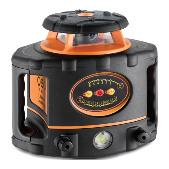
- Page 5 BEDIENELEMENTE 1. Laseraustrittsfenster 2. Rotorkopf 3. Empfangsfenster Fernbedienung 4. Handgriff 5. Libelle für Vertikaleinsatz 6. Justageknopf für Vertikaleinsatz 7 . Bedienfeld 8. Auflagepunkt für Vertikalbetrieb 9. 5/8“-Gewinde vertikal 10. Verschlussschraube Batteriefach 11. Batteriefachdeckel 12. 5/8“-Gewinde horizontal Central 5/8″ screw thread BEDIENUNG Gerät auf eine einigermaßen ebene Fläche setzen oder auf einem Stativ befestigen.
- Page 6 BEDIENUNG AM GERÄT AN/AUS-TASTE (1) Gerät ein- und ausschalten. Wenn die LED (2) rot leuchtet, ist das Gerät eingeschaltet. Nach dem Einschalten nivelliert sich das Gerät automatisch selbst. Wenn die Selbstnivellierung abgeschlossen ist, dreht sich der Rotorkopf mit 800 U/Min. Wenn die AN/AUS-LED (2) im Normalbetrieb zu blinken beginnt, muss der Akku geladen werden.
- Page 7 TILT-FUNKTION (3) Mit dem Einschalten des Gerätes wird automatisch die TILT-Funktion aktiviert; die TILT-LED (4) blinkt während der Aktivierung. Wenn diese abgeschlossen ist (nach ca. 90 Sek.), leuchtet die LED perma- nent. Wenn das Gerät nun aus seiner Lage gebracht wird, stoppt die Rotation, und der Laserstrahl sowie TILT-LED (4) blinken (keine automatische Nachstellung).
- Page 8 HORIZONTALBETRIEB Zur Erstellung eines zweiten Gefälles (z. B. bei Pflasterarbeiten) kann zusätzlich die Y-Achse manuell geneigt werden. Die Bedienung erfolgt mit den Tasten (12) / (13) der Fernbedienung. Eine manuell geneigte Y-Achse wird am Laser mit einer dauerhaft grün leuchtenden LED (2) an- gezeigt.
- Page 9 EMPFÄNGER FR 45 BEDIENELEMENTE 1. Libelle (2) 2. Display 3. Referenzmarke 4. Empfangsfenster 5. AN- / AUS-Schalter 6. Lautsprecher 7 . Batteriefach (Rückseite) 8. Ton an / aus 9. Genauigkeit grob / normal / fein 10. Beleuchtung an / aus 11.
- Page 10 GENAUIGKEITSEINSTELLUNG GROB/ NORMAL / FEIN Der FR 45 ist mit drei Genauigkeitsstufen ausgestattet. Zur Auswahl Taste (9) drücken: Genauigkeit grob ± 10 mm Displaysymbol: leeres Feld Genauigkeit normal ± 4 mm Displaysymbol: Genauigkeit fein ± 2 mm Displaysymbol: EINLEGEN DER BATTERIE •...
- Page 11 EMPFÄNGER FR 77-MM LIEFERUMFANG · Laser-Empfänger FR 77-MM · 4 x AA Alkalinebatterien · Halteklammer für Nivellierlatte · Spezialhalterung · Bedienungsanleitung Technische Daten Genauigkeit 3-stufig ± 2 mm / ± 5 mm / ± 9 mm Genauigkeit mm-Anzeige ± 1 mm Länge Empfangsfenster 125 mm Länge Empfangsbereich mm-Anzeige...
- Page 12 BEDIENELEMENTE Libelle Empfangsfeld Magnet 0SET-Taste (Offset) LED-Anzeige LCD-Anzeige Ton und Beleuchtung Einheiten umstellen ein / aus EIN-/AUS-Taste Empfangsgenauigkeit wählen Libelle Magnet Lautsprecher Arretierung für Halteklammer Gewinde für Halteklammer LED-Anzeige seitlich Markierung Nullposition LCD-Anzeige Rückseite LED-Anzeige hinten Batteriefachdeckel...
- Page 13 Anzeige Einheiten Vorzeichen +/- numerische Anzeige 0SET-Anzeige Anzeige Bezugshöhe Anzeige Genauigkeit Anzeige Beleuchtung Batteriezustandsanzeige Anzeige Ton EIN-/AUS-Taste Schaltet den Empfänger EIN /AUS Taste Empfangsgenauigkeit Auswahl der Empfangsgenauigkeit Taste Einheiten Auswahl der Einheiten Taste Ton / Beleuchtung Ein-/Ausschalten von Ton und Beleuchtung 0SET-Taste Setzen der relativen Null-Position...
- Page 14 STROMVERSORGUNG BATTERIE EINLEGEN / WECHSELN Batteriefachdeckel auf der Rückseite öffnen und 4 x AA Alkalinebatterien einlegen (auf Polarität achten). Batteriefachdeckel wieder schließen. Wenn das Gerät längere Zeit nicht benutzt wird, Batterien herausnehmen. Bei nachlassender Leistung Batterien rechtzeitig wechseln. BATTERIEZUSTANDSANZEIGE Das Display des FR 77-MM zeigt vier verschiedene Batteriezustände an. Sind die Batterien leer, schaltet das Gerät automatisch ab.
- Page 15 BEDIENUNG GERÄT EINSCHALTEN EIN/AUS-Taste einmal drücken, um das Gerät einzuschalten. Für ca. 0,5 Sek. leuchten alle Anzeigen auf (Bild links). Danach befindet sich das Gerät im Empfangsmodus (Anzeige siehe Bild rechts). EMPFANGSGENAUIGKEIT EINSTELLEN Gerät einschalten und mit der Taste „Empfangsgenauigkeit“ auswählen: fein, mittel, grob. Jetzt wird im Display das jeweilige Genauigkeitssymbol und der numerische Wert angezeigt.
- Page 16 DISPLAYBELEUCHTUNG EIN / AUS Gerät einschalten und zum Ein- oder Ausschalten der Hintergrundbeleuchtung Taste „ Ton/Beleuchtung“ gedrückt halten. UMSCHALTEN DER EINHEITEN Gerät einschalten und zum Auswählen der Einheiten Taste „UNITS“ so oft drücken, bis die gewünschte Einheit eingestellt ist. Das Symbol im Display zeigt die jeweilige Einstellung an. Millimeter Zentimeter Inch...
- Page 17 LASERSTRAHL EMPFANGEN Gerät einschalten und Einstellungen festlegen (z. B. Empfangsgenauigkeit fein, Ton laut). Zum Empfangen des Laserstrahls den Empfänger langsam auf und ab bewegen. Anzeige 1 Anzeige 2 Anzeige 3 LED „Laserstrahl hoch“ LED „Laserstrahl tief“ LED „0-Position“ leuchtet = leuchtet.
- Page 18 MM-ANZEIGE Wenn sich die Nullmarkierung des Empfängers z. B. 18 mm unterhalb des Laserstrahls befindet, wird dies durch den genauen Zahlenwert im Display angezeigt (siehe linke Grafik). weitere Beispiele Der Laserstrahl Der Laserstrahl ist Der Laserstrahl ist ist genau auf der 19 mm oberhalb 35 mm unterhalb Nullmarkierung...
- Page 19 ANWENDUNG Zum Empfangen des Laserstrahls die Libelle zentrieren, um die Genauigkeit zu erhöhen. Der Empfänger kann in Verbindung mit der Halteklammer aus dem Lieferumfang an einer Nivellierlatte befestigt werden. SPEZIALHALTERUNG Zur vielseitigen Befestigung z.B. am Schnurgerüst.
- Page 20 SICHERHEITSHINWEISE UMSTÄNDE, DIE DAS MESSERGEBNIS VERFÄLSCHEN KÖNNEN Messungen durch Glas- oder Plastikscheiben; verschmutzte Laseraustrittsfenster; Sturz oder starker Stoß. Bitte Genauigkeit überprüfen. Große Temperaturveränderungen: Wenn das Gerät aus warmer Umgebung in eine kalte oder umgekehrt gebracht wird, vor Benutzung einige Minuten warten. UMGANG UND PFLEGE Messinstrumente generell sorgsam behandeln.
- Page 21 Das Gerät entspricht der Lasersicherheitsklasse 2 gemäß der Norm DIN IEC 60825-1:2014. Das Gerät darf ohne weitere Sicherheitsmaßnahmen eingesetzt werden. Das Auge ist bei zufälligem, kurzzeitigem Hineinsehen in den Laserstrahl durch den Lidschlussreflex geschützt. Laserwarnschilder der Klasse 2 sind gut sichtbar am Gerät angebracht. www.geo-fennel.de G ERMAN Y Laser IEC 60825-1:2014 P ≤...
- Page 22 Dear customer, Thank you for your confidence in us having purchased a geo-FENNEL instrument. This manual will help you to operate the instrument appropriately. Please read the manual carefully - particularly the safety instructions. A proper use only guarantees a longtime and reliable operation.
- Page 23 FEATURES · Single axis grade laser horizontal with vertical function GENERAL HORIZONTAL · TILT function · Self-levelling · Numerical grade setting in X-axis between · VWS function (Vibration-Wind-Security) 0,1% and 6,9% in 0,1% steps · 90° beam to zenith · Dust / water protection IP 66 ·...
- Page 24 POWER SUPPLY Both the standard Li-Ion battery pack and alkaline batteries can be used. 1) Insert alkaline batteries into the alkaline battery box (ensure correct polarity) and fix the battery box into the instrument. 2) Fix the rechargeable battery box into the instrument. Box for alkaline batteries Rechargeable battery box CHARGING THE BATTERY...
- Page 25 KEYPAD AND FUNCTIONS 1. Laser emitting window 2. Rotating head 3. Receiving window remote control 4. Handle 5. Vial for vertical application 6. Adjustment thumb screw for vertical application 7 . Keypad 8. Support for vertical use 9. 5/8“ thread hole vertical 10.
- Page 26 OPERATION - INSTRUMENT KEYPAD ON / OFF BUTTON (1) Press this button to power on and off the unit. If the red LED (2) lights the instrument is powered on. After powering on the instrument the self-levelling procedure starts automatically. Thereafter, the laser will rotate with 800 rpm.
- Page 27 TILT FUNCTION (3) After POWER ON the laser automatically activates the TILT function. The TILT LED (4) is flashing during the activation procedure. When it is completed (after 90 sec. approx.) the LED is illuminated. If the laser is disturbed rotation stops and the laser beam and TILT LED (4) will flash. The laser will not re-level automatically.
- Page 28 HORIZONTAL USE In order to set a second gradient (i. e. paving works) also the Y axis can be tilted manually. The ope- ration is made with the buttons (12) / (13) of the remote control. If the Y axis has been tiled manually the LED (2) of the laser will light green permanently. To quit these slope functions power off the laser first and then power on again.
- Page 29 RECEIVER FR 45 FEATURES 1. Vial (2) 2. Display 3. Reference indicator 4. Receiving window 5. ON / OFF switch 6. Loudspeaker 7 . Battery compartment (back side) 8. Sound on / off 9. Accuracy coarse / normal / fine 10.
- Page 30 ACCURACY COARSE / NORMAL / FINE The FR 45 is equipped with three precision modes. They can be chosen by pressing button (9): Accuracy coarse ± 10 mm Symbol on display: without symbol Accuracy normal ± 4 mm Symbol on display: Accuracy fine ±...
- Page 31 RECEIVER FR 77-MM SUPPLIED WITH · Laser receiver FR 77-MM · 4 x AA alkaline batteries · Clamp for levelling rod · Special mount · User manual Technical Data 3 accuracy settings ± 2 mm / ± 5 mm / ± 9 mm mm-indication accuracy ±...
- Page 32 FEATURES Bubble vial Receiving window Magnetic strip 0SET button (Offset) LED indicators Front LCD Display Sound / illumination Units ON/OFF button Power ON/OFF Accuracy button Bubble vial Magnetic strip Loudspeaker Clamp alignment guide Clamp thread Side LED indicators 0-position (reference point) Rear LCD Display Rear LED indicatiors Battery compartment...
- Page 33 Units of measure Sign +/- Numerical indication 0SET symbol 0-position (reference point) Accuracy symbol Illumination symbol Battery status indicator Sound symbol ON/OFF button Power ON/OFF the receiver Accuracy button Select accuracy setting UNITS button Select units of measure Sound/illumination button Sound and/or illumination ON/OFF 0SET button Set a relative ZERO position...
- Page 34 POWER SUPPLY INSERT / REPLACE BATTERIES Open the battery compartment cover on the rear of the receiver and insert 4 x AA alkaline batteries Refer to the battery compartment diagram to ensure correct polarity. Close the battery compartment cover. Always remove the batteries if the receiver will not be used for a long period of time to avoid leakage. BATTERY STATUS INDICATOR The FR 77-MM front LCD display has four power status symbols.
- Page 35 OPERATION POWER ON Press the ON/OFF button once to power on the receiver. The LCD display will initialise taking about 0.5 seconds when all the display symbols are illuminated (see diagram, left). The receiver is now ready for use (see diagram, right). SELECT ACCURACY SETTING Power on the unit and select the receiving accuracy fine, normal or coarse by pressing the „accuracy button“...
- Page 36 SWITCH ON/OFF THE DISPLAY ILLUMINATION Power on the receiver and keep the button „Sound/illumination“ pressed until the illumination is on. SELECT THE UNITS Power on the receiver and press the „UNITS“ button sucessively until the required unit symbol appears in the display. Millimetre Centimetre Inch...
- Page 37 RECEIVE A LASER BEAM Power on the receiver and make all required settings (i. e. accuracy fine, sound high). Carefully move the receiver up and down to detect the laser beam. Indication 1 Indication 2 Indication 3 The laser beam is high The laser beam is low The LED „0-position“...
- Page 38 MM INDICATION If the reference level of the receiver is e. g. 18 mm below the laser beam this height difference will be displayed by an exact numerical value (see the left diagram). further examples The laser beam is The laser beam is The laser beam is exactly on-level.
- Page 39 APPLICATION Connect the clamp to the receiver for use with a laser pole, levelling staff or similar accessory. For optimum accuracy always level the bubble vials on the receiver before taking measurements. SPECIAL MOUNT To increase the versatility and scope of the receiver a special mount is provided (see illustrations).
- Page 40 SAFETY NOTES SPECIFIC REASONS FOR ERRONEOUS MEASURING RESULTS Measurements through glass or plastic windows; dirty laser emitting windows; after the instrument has been dropped or hit. Please check the accuracy. Large fluctuation of temperature: If the instrument will be used in cold areas after it has been stored in warm areas (or the other way round) please wait some minutes before carrying out measurements.
- Page 41 It is allowed to use the unit without further safety precautions. The eye protection is normally secured by aversion responses and the blink reflex. The laser instrument is marked with class 2 warning labels. www.geo-fennel.de G ERMAN Y Laser IEC 60825-1:2014 P ≤...
-
Page 42: Table Des Matières
Bloc de piles de secours · Support de sol intégré · Coffret rigide · Mode d‘emploi FL 300HV-G EasyGRADE avec cellule FR 45 Réf. 214045 FL 300HV-G EasyGRADE avec cellule FR-DIST 30 Réf. 214050 FL 300HV-G EasyGRADE avec cellule FR 77-MM Réf. 214077... - Page 43 FONCTIONS · Laser simple pente horizontal avec fonction verticale GÉNÉRALITÉS HORIZONTALE · Fonction TILT automatique · Auto-nivellement · Réglage digital de la pente de l‘axe X de · Fonction V-W-S (Anti Vent et Vibration) 0,1% à 6,9% par incréments de 0,1% ·...
-
Page 44: Alimentation En Courant
ALIMENTATION EN COURANT L ’instrument laser est équipé d’un accu Li-Ion. Comme solution de rechange, il peut fonctionner avec des piles alcalines d’usage courant. 1) Mettre en place les piles alcalines dans le logement prévu à cet effet (faire attention à la polarité) et insérer ledit logement dans l’instrument. -
Page 45: Descriptif
DESCRIPTIF 1. Fenêtre de sortie du faisceau laser 2. Tête du laser 3. Fenêtre de réception de télécommande 4. Poignée 5. Bulle pour l‘application en position verticale 6. Vis de bas réglage pour l‘application en position verticale 7 . Clavier 8. - Page 46 OPÉRATION - CLAVIER DE L‘INSTRUMENT TOUCHE DE MARCHE/ARRÊT (1) Mettre en marche/arrêt l‘instrument. La diode (2) est allumée si l‘instrument est en marche. Après sa mise en marche, l’instrument effectue une mise de niveau automatique et puis commence à tourner à 800 trs. Si la diode marche/arrêt (2) commence à...
- Page 47 FONCTION DE TILT (3) La fonction de TILT est automatiquement activée par la mise en marche de l’appareil. La diode de TILT (4) clignote durant cette activation qui s’achève env . 90 sec. après. La diode s’allume alors en perma- nence.
- Page 48 FONCTIONNEMENT HORIZONTAL Pour établir une deuxième pente (p. e. pour des travaux de pavage) également l‘axe Y peut être incliné manuellement. L ‘ opération se fait avec les boutons (12) / (13) de la télécommande. Si l‘axe Y a été incliné manuellement cela est affiché sur le laser par une diode verte rayonnnate permanentement (2).
- Page 49 CELLULE FR 45 DESCRIPTION 1. Nivelle (2) 2. Écran 3. Hauteur de référence 4. Fenêtre de réception 5. Bouton marche/arrêt 6. Haut-parleur 7 . Logement de piles 8. Son marche/arrêt 9. Précision fine / normale / grossière 10. Éclairage marche/arrêt 11.
-
Page 50: Cellule
RÉGLAGE DE LA PRÉCISION FINE / NORMALE / GROSSIÈRE Le FR 45 est équipé de trois niveaux de précision. Pour choisir, pressez bouton (9): Précision grossière ± 10 mm Symbole sur l‘écran: champ vide Précision normale ± 4 mm Symbole sur l‘écran: Précision fine ±... - Page 51 CELLULE FR 77-MM LIVRÉ COMME SUIT · Cellule de réception FR 77-MM · 4 x AA piles alcalines · Support de cellule pour mire · Support spécial · Mode d‘emploi Données techniques 3-niveaux de précision ± 2 mm / ± 5 mm / ± 9 mm Indication de la précision en mm ±...
- Page 52 CARACTÉRISTIQUES Nivelle Fenêtre de réception Aimant Bouton définition du point 0 (Offset) Voyants lumi- Écran neux Son / éclairage Sélection des unités ON/OFF Bouton ON/OFF Sélection de précision Nivelle Aimant Haut-parleur Blocage du support Filetage du support Voyants lumineux du côté...
- Page 53 Unité sélectionnée Signe +/- Nombres Indication 0SET Indication du point de référence Indication du niveau de précision Symbole rétro-éclairage Indication du niveau Symbole du son de la batterie Bouton ON/OFF Allumer l‘appareil ON/OFF Bouton précision Sélection de la précision Bouton unité Sélection des unités Bouton Son/retro-éclairage Activer/désactiver son ou rétro-éclairage...
- Page 54 ALIMENTATION EN COURANT INSÉRER / ENLEVER LES PILES Ouvrez le couvercle du compartiment des piles sur le côté arrière du récepteur et insérez 4 piles alcali- nes AA (prendre soin de polarité). Fermez le couvercle du compartiment des piles. Retirez les piles si vous n‘utilisez pas le récepteur pendant une longue période. Si le niveau des piles devient faible, les piles doivent être échangées.
- Page 55 UTILISATION ALLUMER L ’ A PPAREIL Appuyez sur le bouton ON / OFF une fois pour allumer l‘appareil. Pendant environ 0,5 sec. tous les voyants sont allumés (voir l‘image de gauche). Ensuite, le récepteur est en mode de réception (voir l’image de droite). SÉLECTIONNER LE NIVEAU DE PRÉCISION Allumez l‘appareil et sélectionnez le niveau de précision de réception fine / normale / grossière avec le bouton „Sélection de précision“...
- Page 56 ACTIVER / DÉSACTIVER LE RÉTRO-ÉCLAIRAGE Allumez l‘appareil et maintenez le bouton „Son/rétro-éclairage“ enfoncé jusqu‘à ce que le rétro- éclairage soit allumé. SÉLECTION DES UNITÉS Allumez le récepteur et appuyez sur le bouton „unités“plusieurs fois jusqu‘à ce que l‘unité souhaitée s‘affiche à l‘écran. Millimètre Centimètre Inch...
- Page 57 RÉCEPTION DU FAISCEAU LASER Allumez le récepteur et après avoir fait tous les réglages nécessaires (c‘est à dire la précision, le son). Déplacez le récepteur soigneusement de haut en bas pour détecter le faisceau laser. Indication 1 Indication 2 Indication 3 Le voyant „monter vers le Le voyant „descendre vers le Le voyant „position 0“...
- Page 58 MM INDICATION Si le point 0 de référence du récepteur est par exemple de 18 mm au-dessous du faisceau laser, alors une valeur numérique exacte sera affichée (voir le graphique de gauche). Plusieurs exemples Le faisceau laser Le faisceau laser Le faisceau laser est exactement de est 19 mm au-...
- Page 59 APPLICATION Si nécessaire, monter le FR 77-MM sur son support. Ainsi la cellule peut être fixée sur des mires ou tout autre équipement. Afin d‘augmenter la précision de la cellule centrer la nivelle avant de détecter le faisceau laser. SUPPORT SPÉCIAL Pour différentes fixations, par exemple sur un échafaudage.
-
Page 60: Consignes De Sécurité
CONSIGNES DE SÉCURITÉ CIRCONSTANCES POUVANT FAUSSER LES RÉSULTATS DE MESURES Mesures effectuées à travers des plaques de verre ou de matière plastique; mesures effectuées à travers la fenêtre de sortie du faisceau laser lorsqu‘elle est sale. Mesures après que le niveau soit tombé ou ait subi un choc très fort. Mesures effectuées pendant de grandes différences de température - p. - Page 61 être utilisé sans avoir recours à d’autres mesures de sécurité. Au cas où l’utilisateur a regardé un court instant le faisceau laser, les yeux sont tout de même protégés par le réflexe de fermeture des paupières. Les pictogrammes de danger de la classe 2 sont bien visibles sur le niveau. www.geo-fennel.de GER MANY Laser IEC 60825-1:2014 P ≤...
- Page 62 GmbH Technische Änderungen vorbehalten. Kupferstraße 6 All instruments subject to technical changes. D-34225 Baunatal Sous réserve de modifications techniques. Tel. +49 561 / 49 21 45 +49 561 / 49 72 34 info@geo-fennel.de 12/2019 www.geo-fennel.de Precision by tradition.