Table des Matières

Publicité

Les langues disponibles

Les langues disponibles

Liens rapides

DE | EN | FR
FL 265HV
FLG 265HV-GREEN
BEDIENUNGSANLEITUNG
USER MANUAL
MODE D'EMPLOI
www.geo-fennel.de
www.geo-fennel.com
www.geo-fennel.fr

Publicité

Table des Matières
loading

Sommaire des Matières pour geo-FENNEL FL 265HV

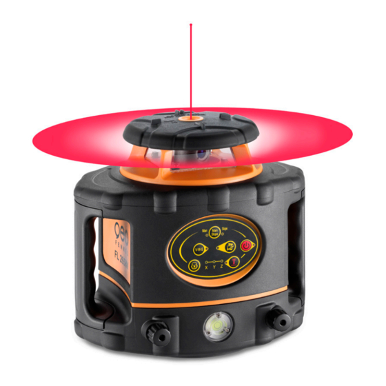
  • Page 1 DE | EN | FR FL 265HV FLG 265HV-GREEN BEDIENUNGSANLEITUNG USER MANUAL MODE D‘EMPLOI www.geo-fennel.de www.geo-fennel.com www.geo-fennel.fr...
  • Page 2: Table Des Matières

    Sehr geehrter Kunde, vielen Dank für das Vertrauen, welches Sie uns beim Erwerb Ihres neuen geo-FENNEL-Gerätes ent- gegengebracht haben. Dieses hochwertige Qualitätsprodukt wurde mit größter Sorgfalt produziert und qualitätsgeprüft. Die beigefügte Anleitung wird Ihnen helfen, das Gerät sachgemäß zu bedienen. Bitte lesen Sie ins- besondere auch die Sicherheitshinweise vor der Inbetriebnahme aufmerksam durch.
  • Page 3 FL 265HV (Laserklasse 2) mit Empfänger FR 45 Art.-Nr. 242021 FL 265HV (Laserklasse 2) mit Empfänger FR 77-MM Art.-Nr. 242098 FL 265HV (Laserklasse 3R) mit Empfänger FR 45 Art.-Nr. 242001 FL 265HV (Laserklasse 3R) mit Empfänger FR 77-MM Art.-Nr. 242078 FLG 265VH-GREEN (Laserklasse 2) ohne Empfänger...
  • Page 4 Abweichende technische Daten für FL 260HV (Klasse 3R) Laserklasse Reichweite mit FR 45 Ø 1000 m Reichweite mit FR 77-MM Ø 600 m Rotierend ohne FR 45 Ø 60 m* Scanning ohne FR 45 60 m* Betriebsdauer / Stromversorgung 40h (Li-Ion) Abweichende technische Daten für FLG 260HV-GREEN (Klasse 2) Laserklasse...
  • Page 5: Bedienelemente

    · Integrierte Bodenauflage mit Rissspitze · · FLG 265HV-GREEN · Alle Funktionen wie beim FL 265HV, jedoch mit gründer Diode · Klare Vorteile im Innenausbau · Erhöhte Sichtbarkeit des Laserstrahls unter schwierigen Bedingungen (helle Umgebung, lange Distanzen, dunkle Messfläche) BEDIENELEMENTE 1.
  • Page 6: Stromversorgung

    STROMVERSORGUNG Der Laser ist mit einem Li-Ion-Akkupack ausgestattet. Alternativ kann er mit handelsüblichen Alkaline- batterien betrieben werden. 1) Alkalinebatterien in das dafür vorgesehene Battriefach einlegen (auf Polarität achten) und das Fach ins Gerät einfügen. ODER 2) Wiederaufladbares Li-Ion-Akkufach ins Gerät einfügen. Akkufach Batteriefach für Alkaline-Batterien AKKU LADEN...
  • Page 7 HORIZONTALEINSATZ Das Gerät auf einer einigermaßen ebenen Fläche oder auf einem Stativ aufstellen. VERTIKALEINSATZ Gerät vertikal (auf der Seite mit dem Gewinde) aufstellen oder mit dem Vertikalgewinde auf einem Stativ befestigen. Direkt nach dem Einschalten beginnt das Gerät, sich selbst zu nivellieren (Laserpunkt blinkt). Wenn der Selbstnivellierungsvorgang abgeschlossen ist, beginnt sich der Rotorkopf zu drehen.
  • Page 8: Tastatur Und Funktionen

    TASTATUR UND FUNKTIONEN Slope adjustment button Area scanning/dot move clockwise Slope adjustment axis direction selection button or anti-clockwise Power LED Area scanning function Remote control sleep button Rotation speed set button...
  • Page 9 AN-/AUS FERNBEDIENUNGSFUNKTION - NUR AM GERÄT (5) Mit der Taste kann die Fernbedienungsfunktion ausgeschaltet werden, um zu vermeiden, dass sich mehrere Geräte FL 265HV / FLG 265HV-GREEN auf einer Baustelle stören. Wenn die LED leuchtet, ist das Gerät für die Fernbedienungsfunktion empfangsbereit.
  • Page 10 NEIGUNGSFUNKTION (12) Neigungen können manuell bis ± 5° (± 9%) eingestellt werden. Mit Taste (12) die jeweilige Neigungsfunktion auswählen. Nach einmaligem Drücken befindet sich das Gerät im SLOPE-Modus. Taste (12) drücken, um zwischen MAN- und SLOPE-Modus zu wechseln. Die Auswahl der Achsen erfolgt mit Taste (14) der Fernbedienung. Taste (14) zum Wechsel zwischen X- und Y-Achse drücken.
  • Page 11 LED FERNBEDIENUNG - AN DER FERNBEDIENUNG (18) Die LED leuchtet bei jedem Steuerimpuls auf, und ein Piepton ist zu hören. STAND-BY-FUNKTION FERNBEDIENUNG (19) Mit dieser Taste wird die Fernbedienung ausgeschaltet, jedoch nicht das Gerät. Durch betätigen der AN/AUS-Taste an der Fernbedienung geht das Gerät in Stand-by-Funktion. Die AN-/AUS-LED am Gerät blinkt.
  • Page 12: Bedienung

    BEDIENUNG Gerät auf eine einigermaßen ebene Fläche setzen oder auf einem Stativ befestigen. Zum Einschalten Taste (1) drücken. Direkt nach dem Einschalten beginnt der Laser automatisch, sich selbst zu nivellieren. Der Laserpunkt und die TILT-LED (4) blinken während dieses Prozesses. Wenn die Selbstnivellierung abgeschlossen ist, beginnt sich der Rotorkopf mit 800 U/Min.
  • Page 13 Bedienung / Funktionen sind identisch zum Horizontalbetrieb – Ausnahmen: Richtungseinstellung im SLOPE-Modus: Um Fehler zu vermeiden, ist nur die Verstellung der X-Achse möglich, die Z-Achse nivelliert sich selbst! Eine gewählte Richtungseinstellung in der X-Achse bleibt erhalten, auch wenn das Gerät ausgeschaltet wird. TILT- und V-W-S- Funktion können zugeschaltet werden.
  • Page 14: Lieferumfang

    EMPFÄNGER FR 45 / FRG 45-GREEN BEDIENELEMENTE 1. Libelle (2) 2. Display 3. Referenzmarke 4. Empfangsfenster 5. AN- / AUS-Schalter 6. Lautsprecher 7 . Batteriefach (Rückseite) 8. Ton an / aus 9. Genauigkeit grob / normal / fein 10. Beleuchtung an / aus 11.
  • Page 15: Einlegen Der Batterie

    GENAUIGKEITSEINSTELLUNG GROB/ NORMAL / FEIN Der FR 45 ist mit drei Genauigkeitsstufen ausgestattet. Zur Auswahl Taste (9) drücken: Genauigkeit grob ± 10 mm Displaysymbol: leeres Feld Genauigkeit normal ± 4 mm Displaysymbol: Genauigkeit fein ± 2 mm Displaysymbol: EINLEGEN DER BATTERIE •...
  • Page 16 EMPFÄNGER FR 77-MM LIEFERUMFANG · Laser-Empfänger FR 77-MM · 4 x AA Alkalinebatterien · Halteklammer für Nivellierlatte · Spezialhalterung · Bedienungsanleitung Technische Daten Genauigkeit 3-stufig ± 2 mm / ± 5 mm / ± 9 mm Genauigkeit mm-Anzeige ± 1 mm Arbeitsbereich Laser rot, LK 2 Ø...
  • Page 17 BEDIENELEMENTE Libelle Empfangsfeld Magnet 0SET-Taste (Offset) LED-Anzeige LCD-Anzeige Ton und Beleuchtung Einheiten umstellen ein / aus EIN-/AUS-Taste Empfangsgenauigkeit wählen Libelle Magnet Lautsprecher Arretierung für Halteklammer Gewinde für Halteklammer LED-Anzeige seitlich Markierung Nullposition LCD-Anzeige Rückseite LED-Anzeige hinten Batteriefachdeckel...
  • Page 18 Anzeige Einheiten Vorzeichen +/- numerische Anzeige 0SET-Anzeige Anzeige Bezugshöhe Anzeige Genauigkeit Anzeige Beleuchtung Batteriezustandsanzeige Anzeige Ton EIN-/AUS-Taste Schaltet den Empfänger EIN /AUS Taste Empfangsgenauigkeit Auswahl der Empfangsgenauigkeit Taste Einheiten Auswahl der Einheiten Taste Ton / Beleuchtung Ein-/Ausschalten von Ton und Beleuchtung 0SET-Taste Setzen der relativen Null-Position...
  • Page 19: Batterie Einlegen / Wechseln

    STROMVERSORGUNG BATTERIE EINLEGEN / WECHSELN Batteriefachdeckel auf der Rückseite öffnen und 4 x AA Alkalinebatterien einlegen (auf Polarität achten). Batteriefachdeckel wieder schließen. Wenn das Gerät längere Zeit nicht benutzt wird, Batterien herausnehmen. Bei nachlassender Leistung Batterien rechtzeitig wechseln. BATTERIEZUSTANDSANZEIGE Das Display des FR 77-MM zeigt vier verschiedene Batteriezustände an. Sind die Batterien leer, schaltet das Gerät automatisch ab.
  • Page 20: Gerät Einschalten

    BEDIENUNG GERÄT EINSCHALTEN EIN/AUS-Taste einmal drücken, um das Gerät einzuschalten. Für ca. 0,5 Sek. leuchten alle Anzeigen auf (Bild links). Danach befindet sich das Gerät im Empfangsmodus (Anzeige siehe Bild rechts). EMPFANGSGENAUIGKEIT EINSTELLEN Gerät einschalten und mit der Taste „Empfangsgenauigkeit“ auswählen: fein, mittel, grob. Jetzt wird im Display das jeweilige Genauigkeitssymbol und der numerische Wert angezeigt.
  • Page 21 DISPLAYBELEUCHTUNG EIN / AUS Gerät einschalten und zum Ein- oder Ausschalten der Hintergrundbeleuchtung Taste „ Ton/Beleuchtung“ gedrückt halten. UMSCHALTEN DER EINHEITEN Gerät einschalten und zum Auswählen der Einheiten Taste „UNITS“ so oft drücken, bis die gewünschte Einheit eingestellt ist. Das Symbol im Display zeigt die jeweilige Einstellung an. Millimeter Zentimeter Inch...
  • Page 22 LASERSTRAHL EMPFANGEN Gerät einschalten und Einstellungen festlegen (z. B. Empfangsgenauigkeit fein, Ton laut). Zum Empfangen des Laserstrahls den Empfänger langsam auf und ab bewegen. Anzeige 1 Anzeige 2 Anzeige 3 LED „Laserstrahl hoch“ LED „Laserstrahl tief“ LED „0-Position“ leuchtet = leuchtet.
  • Page 23 MM-ANZEIGE Wenn sich die Nullmarkierung des Empfängers z. B. 18 mm unterhalb des Laserstrahls befindet, wird dies durch den genauen Zahlenwert im Display angezeigt (siehe linke Grafik). weitere Beispiele Der Laserstrahl Der Laserstrahl ist Der Laserstrahl ist ist genau auf der 19 mm oberhalb 35 mm unterhalb Nullmarkierung...
  • Page 24 SPEZIALHALTERUNG Zur vielseitigen Befestigung z.B. am Schnurgerüst.
  • Page 25: Sicherheitshinweise

    SICHERHEITSHINWEISE UMSTÄNDE, DIE DAS MESSERGEBNIS VERFÄLSCHEN KÖNNEN Messungen durch Glas- oder Plastikscheiben; verschmutzte Laseraustrittsfenster; Sturz oder starker Stoß. Bitte Genauigkeit überprüfen. Große Temperaturveränderungen: Wenn das Gerät aus warmer Umgebung in eine kalte oder umgekehrt gebracht wird, vor Benutzung einige Minuten warten. UMGANG UND PFLEGE Messinstrumente generell sorgsam behandeln.
  • Page 26: Bestimmungsgemässe Verwendung

    Das Gerät entspricht der Lasersicherheitsklasse 2 gemäß der Norm DIN IEC 60825-1:2014. Das Gerät darf ohne weitere Sicherheitsmaßnahmen eingesetzt werden. Das Auge ist bei zufälligem, kurzzeitigem Hineinsehen in den Laserstrahl durch den Lidschlussreflex geschützt. Laserwarnschilder der Klasse 2 sind gut sichtbar am Gerät angebracht. www.geo-fennel.de G ERMAN Y Laser IEC 60825-1:2014 P ≤...
  • Page 27: Warn- Und Sicherheitshinweise

    Laserstrahl nicht ungewollt auf Flächen fällt, die wie ein Spiegel reflektieren und dass Personen nicht direkt in den Strahl blicken. Laserwarnschilder der Klasse 3R sind gut sichtbar am Gerät angebracht. www.geo-fennel.de G ERMAN Y Laser IEC 60825-1:2014...
  • Page 28 Dear customer, Thank you for your confidence in us having purchased a geo-FENNEL instrument. This manual will help you to operate the instrument appropriately. Please read the manual carefully - particularly the safety instructions. A proper use only guarantees a longtime and reliable operation.
  • Page 29: Technical Data

    FL 265HV (laser class 2) with receiver FR 45 Art. no. 242021 FL 265HV (laser class 2) with receiver FR 77-MM Art. no. 242098 FL 265HV (laser class 3R) with receiver FR 45 Art. no. 242001 FL 265HV (laser class 3R) with receiver FR 77-MM Art.
  • Page 30: Functions

    Varying technical data for FL 265HV (class 3R) Laser class Working range with FR 45 Ø 1000 m Working range with FR 77-MM Ø 600 m Rotating w/o FR 45 Ø 60 m* Scanning w/o FR 45 60 m* Power supply / operation...
  • Page 31 Integrated floor mount with datum point · FLG 265HV-GREEN · Same functions as FL 265HV, but with green laser diode · Ideally suited for indoor applications · Improved visibility of laser beam. Especially useful in bright surroundings and over longer distances.
  • Page 32: Power Supply

    POWER SUPPLY Both the standard Li-Ion battery pack and alkaline batteries can be used. 1) Insert alkaline batteries into the alkaline battery box (ensure correct polarity) and fix the battery box into the instrument. 2) Fix the rechargeable battery box into the instrument. Box for alkaline batteries Rechargeable battery box CHARGING THE BATTERY...
  • Page 33: Vertical Use

    HORIZONTAL USE Set up the instrument on an even surface or mount it onto a tripod. VERTICAL USE Set up the instrument vertically (on the side with the vertical 5/8“ hole) or mount it onto a tripod with its vertical 5/8“ thread. After powering on the unit a flashing laser diode indicates that the automatic self-levelling procedure is working.
  • Page 34 KEYPAD AND FUNCTIONS Slope adjustment button Area scanning/dot move clockwise Slope adjustment axis direction selection button or anti-clockwise Power LED Area scanning function Remote control sleep button Rotation speed set button...
  • Page 35: Tilt Function

    ON / OFF BUTTON (2) Press this button to power on and off the unit. If the red LED (1) lights the instrument is powered on. After powering on the instrument the self-levelling procedure starts automatically. Thereafter, the laser will rotate with 800 rmp. If in normal use the LED (1) flashes the battery has to be recharged.
  • Page 36: Scanning Mode

    SLOPE MODE (12) Slopes can be set manually up to 5° (± 9 %). Select the SLOPE function with button (12). Press button (12) once to select the SLOPE mode and a second time for the MAN mode. Choose the relevant axis (X, Y, Z) by pressing button (14) of the remote control. The axis chosen will be indicated by the LEDs (7).
  • Page 37 LED (14) - REMOTE CONTROL - REMOTE BUTTON (18) This LED flashes if any button is used and a beep sounds. ON / OFF REMOTE CONTROL FUNCTION - REMOTE BUTTON (19) With this button the remote control can be powered off - but not the instrument. Press the ON/OFF button of the remote;...
  • Page 38 OPERATION Set-up the laser on a flat and even surface or mount onto a tripod. Press the ON/OFF button (1) to power on the laser. After POWER ON the laser automatically self-levels. The laser beam and the TILT LED (4) flash indica- ting that the automatic self-levelling procedure is activated.
  • Page 39 All functions are identical to those in the horizontal position with following exceptions: In SOPE mode the X axis can be set manually, the Z axis is automatically self-levelled. The TILT and / or V-W-S function can be activated. If a slope has been set in the X axis and the laser is tempo- rarily powered off, the axis will retain its original position when the laser is powered on again.
  • Page 40: Supplied With

    RECEIVER FR 45 / FRG 45-GREEN FEATURES 1. Vial (2) 2. Display 3. Reference indicator 4. Receiving window 5. ON / OFF switch 6. Loudspeaker 7 . Battery compartment (back side) 8. Sound on / off 9. Accuracy coarse / normal / fine 10.
  • Page 41 ACCURACY COARSE / NORMAL / FINE The FR 45 / FRG 45-GREEN is equipped with three precision modes. They can be chosen by pressing button (9): Accuracy coarse ± 10 mm Symbol on display: without symbol Accuracy normal ± 4 mm Symbol on display: Accuracy fine ±...
  • Page 42 RECEIVER FR 77-MM SUPPLIED WITH · Laser receiver FR 77-MM · 4 x AA alkaline batteries · Clamp for levelling rod · Special mount · User manual Technical Data 3 accuracy settings ± 2 mm / ± 5 mm / ± 9 mm mm-indication accuracy ±...
  • Page 43 FEATURES Bubble vial Receiving window Magnetic strip 0SET button (Offset) LED indicators Front LCD Display Sound / illumination Units ON/OFF button Power ON/OFF Accuracy button Bubble vial Magnetic strip Loudspeaker Clamp alignment guide Clamp thread Side LED indicators 0-position (reference point) Rear LCD Display Rear LED indicatiors Battery compartment...
  • Page 44 Units of measure Sign +/- Numerical indication 0SET symbol 0-position (reference point) Accuracy symbol Illumination symbol Battery status indicator Sound symbol ON/OFF button Power ON/OFF the receiver Accuracy button Select accuracy setting UNITS button Select units of measure Sound/illumination button Sound and/or illumination ON/OFF 0SET button Set a relative ZERO position...
  • Page 45: Power Supply

    POWER SUPPLY INSERT / REPLACE BATTERIES Open the battery compartment cover on the rear of the receiver and insert 4 x AA alkaline batteries Refer to the battery compartment diagram to ensure correct polarity. Close the battery compartment cover. Always remove the batteries if the receiver will not be used for a long period of time to avoid leakage. BATTERY STATUS INDICATOR The FR 77-MM front LCD display has four power status symbols.
  • Page 46: Operation

    OPERATION POWER ON Press the ON/OFF button once to power on the receiver. The LCD display will initialise taking about 0.5 seconds when all the display symbols are illuminated (see diagram, left). The receiver is now ready for use (see diagram, right). SELECT ACCURACY SETTING Power on the unit and select the receiving accuracy fine, normal or coarse by pressing the „accuracy button“...
  • Page 47 SWITCH ON/OFF THE DISPLAY ILLUMINATION Power on the receiver and keep the button „Sound/illumination“ pressed until the illumination is on.Ocrenatquit veriocus poenti in ducipsedes es? Qua Sen tum tum is, nostasdam imoraete essus. Ce maio, is derium hi, Ti. Conum rei caetere, sedienatiam quam inatiem senitil larebus acerfin re cludes la SELECT THE UNITS Power on the receiver and press the „UNITS“...
  • Page 48 RECEIVE A LASER BEAM Power on the receiver and make all required settings (i. e. accuracy fine, sound high). Carefully move the receiver up and down to detect the laser beam. Indication 1 Indication 2 Indication 3 The laser beam is high The laser beam is low The LED „0-position“...
  • Page 49 MM INDICATION If the reference level of the receiver is e. g. 18 mm below the laser beam this height difference will be displayed by an exact numerical value (see the left diagram). further examples The laser beam is The laser beam is The laser beam is exactly on-level.
  • Page 50 APPLICATION Connect the clamp to the receiver for use with a laser pole, levelling staff or similar accessory. For optimum accuracy always level the bubble vials on the receiver before taking measurements. SPECIAL MOUNT To increase the versatility and scope of the receiver a special mount is provided (see illustrations).
  • Page 51: Safety Notes

    SAFETY NOTES SPECIFIC REASONS FOR ERRONEOUS MEASURING RESULTS Measurements through glass or plastic windows; dirty laser emitting windows; after the instrument has been dropped or hit. Please check the accuracy. Large fluctuation of temperature: If the instrument will be used in cold areas after it has been stored in warm areas (or the other way round) please wait some minutes before carrying out measurements.
  • Page 52: Intended Use Of Instrument

    It is allowed to use the unit without further safety precautions. The eye protection is normally secured by aversion responses and the blink reflex. The laser instrument is marked with class 2 warning labels. www.geo-fennel.de G ERMAN Y Laser IEC 60825-1:2014 P ≤...
  • Page 53: Safety Instructions

    The legal requirement for using class 3R laser product will vary from country to country. The user is responsible for compliance to national standards and regulations. · Non-observance may lead to injuries. www.geo-fennel.de G ERMAN Y Laser IEC 60825-1:2014 P ≤ 5 mW @ 635 - 670 nm...
  • Page 54: Livré Comme Suit

    4. Clavier et fonctions 5. Opération 6. Cellule 7 . Consignes de sécurité LIVRÉ COMME SUIT · Laser rotatif FL 265HV / FLG 265HV-GREEN · Cellule FR 45 / FRG 45-Green avec son support · Cellule FR 77-MM avec son support ·...
  • Page 55: Données Techniques

    FL 265HV (classe de laser 2) avec cellule FR 45 Réf. 242021 FL 265HV (classe de laser 2) avec cellule FR 77-MM Réf. 242098 FL 265HV (classe de laser 3R) avec cellule FR 45 Réf. 242001 FL 265HV (classe de laser 3R) avec cellule FR 77-MM Réf.
  • Page 56 Données techniques divergentes pour FL 265HV (classe 3R) Classe de laser Portée avec FR 45 Ø 1000 m Portée avec FR 77-MM Ø 600 m Par rotation (sans FR 45) Ø 60 m* Fonction de scan (sans FR 45) 60 m*...
  • Page 57: Descriptif

    · · FLG 265HV-GREEN · Toutes les fonctions identiques à FL 265HV, mais avec diode à laser de couleur verte · Avantages réels pour aménagements intérieurs · Visibilité plus élevée du faisceau laser dans des conditions d’emploi difficiles (environnement clair, longues distances, surface mesurée sombre)
  • Page 58: Alimentation En Courant

    ALIMENTATION EN COURANT L ’instrument laser est équipé d’un accu Li-Ion. Comme solution de rechange, il peut fonctionner avec piles alcalines d’usage courant. 1) Mettre en place les piles alcalines dans le logement prévu à cet effet (faire attention à la polarité) et insérer ledit logement dans l’instrument.
  • Page 59: Emploi Avec Faisceau Horizontal

    EMPLOI AVEC FAISCEAU HORIZONTAL Placer l’instrument sur une surface à peu près horizontale ou sur un trépied. EMPLOI AVEC FAISCEAU VERTICAL Placer l’instrument avec faisceau à la verticale (filetage se trouvant sur le côté) ou fixer son filetage vertical sur un trépied. Après la mise en marche, l’instrument se met à...
  • Page 60: Clavier Et Fonctions

    CLAVIER ET FONCTIONS Slope adjustment button Slope adjustment axis Area scanning/dot move clockwise direction selection button or anti-clockwise Power LED Area scanning function Remote control sleep button Rotation speed set button...
  • Page 61 TOUCHE DE MARCHE/ARRÊT (2) Mettre en marche/arrêt l‘instrument. La diode (1) est allumée si l‘instrument est en marche. Après sa mise en marche, l’instrument effectue une mise de niveau automatique et puis commence à tourner à 800 trs. Si la diode marche/arrêt (1) commence à clignoter en utilisaiton normale il faut alors recharger l‘accu. FONCTION DE TILT (3) La fonction de TILT est automatiquement activée par la mise en marche de l’appareil.
  • Page 62: Fonction D'inclinaison

    FONCTION D‘INCLINAISON (12) On peut régler manuellement les inclinaisons jusqu’à ± 5° (± 9%). Choisir la fonction d’inclinaison momentanée avec la touche (12). Après une première pression l’appareil se trouve en mode SLOPE. Presser de de nouveau la touche (12) pour passer du mode SLOPE au mode MAN et inversement.
  • Page 63: Fonction Stand-By

    LED TÉLÉCOMMANDE - TOUCHE TÉLÉCOMMANDE (18) La diode est allumée en cas de toute pression d‘une touche et en plus un signal sonore retentit. FONCTION STAND-BY (19) Cette touche met hors service la télécommande - mais pas le laser. En pressent la touche MARCHE/ARRÊT de la télécommande l‘instrument se met en état stand-by (veille).
  • Page 64: Opération

    OPÉRATION Placer l’appareil sur une surface à peu près plane ou l’installer sur le trépied. Presser le bouton (1) pour mettre l’appareil en marche. Dès la mise en marche, le laser commence à s‘autoniveler (le point de laser clignote). Lorsque le nivel- lement est achevé...
  • Page 65 Manoeuvre / les fonctions sont identiques à la marche sur plan horizontal - exceptions: Réglage de direction en mode SLOPE: Pour éviter des erreurs, seule est possible la modification de réglage de l’axe X, l’axe Z se nivelant par lui-même! Le réglage de direction choisi pour l’axe X est con- servé, même après avoir arrêté...
  • Page 66 CELLULE FR 45 / FRG 45-GREEN DESCRIPTION 1. Nivelle (2) 2. Écran 3. Hauteur de référence 4. Fenêtre de réception 5. Bouton marche/arrêt 6. Haut-parleur 7 . Logement de piles 8. Son marche/arrêt 9. Précision fine / normale / grossière 10.
  • Page 67: Mise En Place De Piles

    RÉGLAGE DE LA PRÉCISION FINE / NORMALE / GROSSIÈRE Le FR 45 / FRG 45-GREEN est équipé de trois niveaux de précision. Pour choisir, presser bouton (9): Précision grossière ± 10 mm Symbole sur l‘écran: champ vide Précision normale ± 4 mm Symbole sur l‘écran: Précision fine ±...
  • Page 68: Caractéristiques

    CELLULE FR 77-MM LIVRÉ COMME SUIT · Cellule de réception FR 77-MM · 4 x AA piles alcaline · Support de cellule pour mire · Support spécial · Mode d‘emploi Données techniques 3-niveaux de précision ± 2 mm / ± 5 mm / ± 9 mm Indication de la précision en mm ±...
  • Page 69 CARACTÉRISTIQUES Nivelle Fenêtre de réception Aimant Bouton définition du point 0 (Offset) Voyants lumi- Écran neux Son / éclairage Sélection des unités ON/OFF Bouton ON/OFF Sélection de précision Nivelle Aimant Haut-parleur Blocage du support Filetage du support Voyants lumineux du côté...
  • Page 70 Unité sélectionnée Signe +/- Nombres Indication 0SET Indication du point de référence Indication du niveau de précision Symbol retro-éclairage Indication du niveau Symbole du son de la batterie Bouton ON/OFF Allumer l‘appareil ON/OFF Bouton précision Sélection de la précision Bouton unité Sélection des unités Bouton Son/retro-éclairage Activer/désactiver son ou retro-éclairage...
  • Page 71: Insérer / Enlever Les Piles

    ALIMENTATION EN COURANT INSÉRER / ENLEVER LES PILES Ouvrez le couvercle du compartiment des piles sur le côté arrière du récepteur et insérez 4 piles alcali- nes AA (prendre soin de polarité). Fermez le couvercle du compartiment des piles. Retirez les piles si vous n‘utilisez pas le récepteur pendant une longue période. Si le niveau des piles devient faible, les piles doivent être échangées.
  • Page 72: Utilisation

    UTILISATION ALLUMER L ’ A PPAREIL Appuyez sur le bouton ON / OFF une fois pour allumer l‘appareil. Pendant environ 0,5 sec. tous les voyants sont allumés (voir l‘image de gauche). Ensuite, le récepteur est en mode de réception (voir l’image de droite). SÉLECTIONNER LE NIVEAU DE PRÉCISION Allumez l‘appareil et sélectionnez le niveau de précision de réception fine / normale / grossière avec le bouton „Sélection de précision“...
  • Page 73: Activer / Désactiver Le Retro-Éclairage

    ACTIVER / DÉSACTIVER LE RETRO-ÉCLAIRAGE Allumez l‘appareil et maintenez le bouton „Son/rétro-éclairage“ enfoncée jusqu‘à ce que le rétro- éclairage soit allumé. SÉLECTION DES UNITÉS Allumez le récepteur et appuyez sur le bouton „unités“plusieurs fois jusqu‘à ce que l‘unité souhaitée s‘affiche à l‘écran. Millimèetre Centimètre Inch...
  • Page 74: Réception Du Faisceau Laser

    RÉCEPTION DU FAISCEAU LASER Allumez le récepteur et après avoir fait tous les réglages nécessaires (c‘est à dire la précision, le son). Déplacez le récepteur soigneusement de haut en bas pour détecter le faisceau laser. Indication 1 Indication 2 Indication 3 Le voyant „monter vers le Le voyant „descendre vers le Le voyant „position 0“...
  • Page 75: Position 0 Relative (Point De Référence)

    MM INDICATION Si le point 0 de référence du récepteur est par exemple de 18 mm au-dessous du faisceau laser, alors une valeur numérique exacte sera affichée (voir le graphique de gauche). Plusieurs exemples Le faisceau laser Le faisceau laser Le faisceau laser est exactement de est 19 mm au-...
  • Page 76 APPLICATION Si nécessaire, monter le FR 77-MM sur son support. Ainsi la cellule peut être fixée sur des mires ou tout autre équipement. Afin d‘augmenter la précision de la cellule centrer la nivelle avant de détecter le faisceau laser. SUPPORT SPÉCIAL Pour différentes fixations, par exemple sur un échafaudage.
  • Page 77: Consignes De Sécurité

    CONSIGNES DE SÉCURITÉ CIRCONSTANCES POUVANT FAUSSER LES RÉSULTATS DE MESURES Mesures effectuées à travers des plaques de verre ou de matière plastique; mesures effectuées à travers la fenêtre de sortie du faisceau laser lorsqu‘elle est sale. Mesures après que le niveau soit tombé ou ait subi un choc très fort. Mesures effectuées pendant de grandes différences de température - p.
  • Page 78: Exclusion De La Responsabilité

    être utilisé sans avoir recours à d’autres mesures de sécurité. Au cas où l’utilisateur a regardé un court instant le faisceau laser, les yeux sont tout de même protégés par le réflexe de fermeture des paupières. Les pictogrammes de danger de la classe 2 sont bien visibles sur le niveau. www.geo-fennel.de G ERMAN Y Laser IEC 60825-1:2014 P ≤...
  • Page 79: Indications D' A Vertissement Et De Sécurité

    Ne pas utiliser le niveau dans un milieu à risque d’explosions. Les pictogrammes de danger de la classe 3 sont bien visibles sur le niveau. www.geo-fennel.de G ERMAN Y Laser IEC 60825-1:2014 P ≤...
  • Page 80 GmbH Technische Änderungen vorbehalten. Kupferstraße 6 All instruments subject to technical changes. D-34225 Baunatal Sous réserve de modifications techniques. Tel. +49 561 / 49 21 45 +49 561 / 49 72 34 info@geo-fennel.de 12/2016 www.geo-fennel.de Precision by tradition.

Ce manuel est également adapté pour:

Flg 265hv-green

Table des Matières