Abicor Binzel MFS-V2 Mode D'emploi

Abicor Binzel MFS-V2 Mode D'emploi

Dévidoir
Masquer les pouces Voir aussi pour MFS-V2:
Table des Matières

Publicité

Les langues disponibles
  • FR

Les langues disponibles

  • FRANÇAIS, page 46

Liens rapides

T E C H N O L O G Y F O R T H E W E L D E R ´ S W O R L D .
DE Betriebsanleitung / GB Operating instructions
FR Mode d'emploi / ES Instructivo de servicio
JP 取扱説明書 / ZH 使用说明
DE Drahtvorschubsystem MFS-V2
EN Wire feeding system MFS-V2
FR Système de dévidoir MFS-V2
ES Devanadora MFS-V2
JP ワイヤ送給システム MFS-V2
ZH 焊丝输入装置 MFS-V2
EN 60 974-5
GB/T 15579.5
www.binzel-abicor.com

Publicité

Table des Matières
loading

Sommaire des Matières pour Abicor Binzel MFS-V2

  • Page 1 DE Betriebsanleitung / GB Operating instructions FR Mode d’emploi / ES Instructivo de servicio JP 取扱説明書 / ZH 使用说明 DE Drahtvorschubsystem MFS-V2 EN Wire feeding system MFS-V2 FR Système de dévidoir MFS-V2 ES Devanadora MFS-V2 JP ワイヤ送給システム MFS-V2 ZH 焊丝输入装置 MFS-V2 EN 60 974-5 GB/T 15579.5...
  • Page 2: Table Des Matières

    Original Betriebsanleitung MFS-V2 Original Betriebsanleitung © Der Hersteller behält sich das Recht vor, jederzeit und ohne vorherige Mitteilung Änderungen an dieser Betriebsanleitung durchzuführen, die durch Druckfehler, eventuelle Ungenauigkeiten der enthaltenen Informationen oder Verbesserung dieses Produktes erforderlich werden. Diese Änderungen werden jedoch in neuen Ausgaben berücksichtigt.
  • Page 3: Identifikation

    MFS-V2 1 Identifikation 1 Identifikation Das Drahtvorschubsystem MFS-V2 wird in der Industrie und im Gewerbe zur Förderung von Schweißzusatzwerkstoffen eingesetzt. Es besteht aus E-Box und M-Drive. Die E-Box beinhaltet alle elektronischen Ansteuerelemente, der M-Drive den 4-Rollensnatrieb zur Drahtförderung. Der modulare Aufbau gestattet eine individuelle mechanische und elektronische Anpassung über E/A oder digitale...
  • Page 4: Technische Daten De

    2 Produktbeschreibung MFS-V2 2.3 Technische Daten Ø Ø Abb. 1 Abmessungen E-Box Abb. 2 Abmessungen M-Drive Temperatur der Umgebungsluft - 10 °C bis + 40 °C Transport und Lagerung - 10 °C bis + 55 °C Relative Luftfeuchtigkeit bis 90 % bei 20 °C Tab.
  • Page 5 MFS-V2 2 Produktbeschreibung Leistungsaufnahme 1,5 kW Schutzart IP21 Tab. 4 E-Box Drahtspulenhalterung für Korbspule K 300 mm Drahtförderschlauch max. 6 m Isolierplatte Tab. 5 Zubehör 2.4 Abkürzungen MFS-V2 Drahtvorschubeinheit (Slave und E-Box) zum Master Feeder System Antriebseinheit (Master) Baugröße 1 = Rollen-ø 20 mm Antriebseinheit (Master) Baugröße 2 = Rollen-ø...
  • Page 6: Sicherheitshinweise

    Tab. 7 Lieferumfang Ausrüst- und Verschleißteile separat bestellen. Bestelldaten und Ident-nummern der Ausrüst- und Verschleißteile entnehmen Sie den aktuellen ABICOR BINZEL Ersatz- und Verschleißteilpreislisten. Kontakt für Beratung und Bestellung finden Sie im Internet unter www.binzel-abicor.com. 4.1 Transport Der Lieferumfang wird vor dem Versand sorgfältig geprüft und verpackt, jedoch sind Beschädigungen während des Transportes nicht auszuschließen.
  • Page 7: Funktionsbeschreibung

    Transport 4.2 Lagerung Physikalische Bedingungen der Lagerung im geschlossenen Raum:  Siehe Tab. 2 Temperatur auf Seite DE-4 5 Funktionsbeschreibung Das Drahtvorschubsystem MFS-V2 besteht aus E-Box und M-Drive. Folgende Komponenten sind im Master- Feeder-System MF enthalten: M-Drive E-Box MF 1/2...
  • Page 8: Inbetriebnahme

    6 Inbetriebnahme MFS-V2 6 Inbetriebnahme GEFAHR Verletzungsgefahr durch unerwarteten Anlauf Für die gesamte Dauer von Wartungs-, Instandhaltungs-, Demontage- und Reparaturarbeiten ist folgendes zu beachten: • Schalten Sie die Stromquelle aus. • Sperren Sie die Druckluftzufuhr ab. • Ziehen Sie den Netzstecker.
  • Page 9: Medienanschlüsse Am M-Drive Herstellen De

    MFS-V2 6 Inbetriebnahme 6.3 Medienanschlüsse am M-Drive herstellen Verbinden Sie folgende Anschlüsse miteinander: Ausblasen Ausgang Schweißkabelanschluss Kühlmittelvorlauf Eingang Kühlmittelrücklauf Ausgang Ausblasen Eingang Kühlmittelrücklauf Eingang Kühlmittelvorlauf Ausgang Schlauchpaket Gas Eingang Abb. 7 Anschlussschema 6.4 Netzanschluss GEFAHR Stromschlag Gefährliche Spannung durch fehlerhafte Kabel.
  • Page 10: Draht Einfädeln De

    6 Inbetriebnahme MFS-V2 6.5 Draht einfädeln Deckel M-Drive Zwischenanschluss Einlaufrohr Druckhebel Druckwippe 2 Stk. Antriebsrollen Sicherheitsschalter Abb. 8 Draht einfädeln 1 Deckel (1) am M-Drive (2) öffnen. 2 Druckhebel (2) nach vorne klappen und Druckwippen (3) öffnen. 3 Drahtanfang an der Korbspule lösen.
  • Page 11: Antriebsrollen Wechseln De

    MFS-V2 6 Inbetriebnahme 6.6 Antriebsrollen wechseln Druckwippe 2 Stk. Steckachse 2 Stk. Halteschrauben 2 Stk. Druckhebel Druckrollen 2 Stk. Antriebsrollen 2 Stk. Abb. 9 Antriebsrollen wechseln HINWEIS • Welchseln bzw. wenden Sie die Antriebsrollen immer paarweise. • Achten Sie auf die Nutgeometrie und den Drahtdurchmesser.
  • Page 12 6 Inbetriebnahme MFS-V2 6.7 Steckerbelegung M-Drive E-Box Steuerleitung MF-Paket Option Handterminal Steuerleitung E-Box - Roboter Steuerleitung M-Drive - E-Box Schnittstelle Memory Modul Programmierschnittstelle Abb. 10 Steckerbelegung Übersicht Beschreibung Signals X41 Pin Drehgeber Drehgeber Drehgeber Stby Drehgeber Ch A Drehgeber Ch B...
  • Page 13 MFS-V2 6 Inbetriebnahme X46 Pin Beschreibung Signals X47 Pin Istwertgeber Istwertgeber Ch A Istwertgeber Ch B Motor Master Motor Master Motor Slave Motor Slave Klemmleiste 24V für Inching/Init/Reverse Inching Geschaltet zurück Reset Gechaltet zurück Inching Rückzug Geschaltet zurück Gastest Gasventil...
  • Page 14: Betrieb

    Ready In Ready Out Reset Reset 24V geschaltet Inching Inching 24V geschaltet Erdkreisüberwachung Erdkreisüberwachung Drahtistwert 0 ... 10V Drahtistwert Tab. 11 Steuerleitung E-Box - Roboter 7 Betrieb HINWEIS • Die Bedienung des Drahtvorschubsystems MFS-V2 ist ausschließlich Fachkräften vorbehalten. DE - 14...
  • Page 15: Bedienelemente

    MFS-V2 7 Betrieb 7.1 Bedienelemente Sie können den Schlüssel in jeder Schalterstellung abziehen. Status LED V1 Master Anschluss X47 Anschlusskabel mit Netzstecker 13 Anschluss Handterminal Reset Taster S4 Steuerleitung B M-Drive Luftgitter 14 Anschluss X43 Steuerleitung C Drahtvorlauf S3 Inching...
  • Page 16: Außerbetriebnahme

    8 Außerbetriebnahme MFS-V2 Symbol Bezeichnung Schlüsselschalter S2 (4) Abb. (11) Auto Schaltzustand Automatik: Drahtvorschub ist bei geschlossenem Deckel (M-Drive) uneingeschränkt funktionsfähig Hand Schaltzustand Hand: Die Schutzeinrichtung ist überrückt. Die Funktion Inching (Draht einfädeln) ist bei offenem Deckel (M-Drive) freigeschaltet. In jeder anderen, möglichen Situation bleiben die Antriebe stromlos und das Startsignal unterbrochen.
  • Page 17: Wöchentlich Reinigen De

    MFS-V2 10 Störungen und deren Behebung 9.1 Wöchentlich reinigen 1 Schlauchpaket maschinenseitig lösen und in gestreckte Position bringen. 2 Überwurfmutter abschrauben und Führungsspirale bzw. Kunststoffseele herausziehen. WARNUNG Verletzungsgefahr Schwere Verletzungen durch herumwirbelnde Teile. • Tragen Sie beim Ausblasen der Drahtführung geeignete Schutzkleidung, insbesondere eine Schutzbrille.
  • Page 18: Entsorgung

    Betriebsmittelhersteller vorgegebenen Sicherheitsdatenblätter. Kontaminierte Reinigungswerkzeuge (Pinsel, Lappen usw.) müssen ebenfalls entsprechend den Angaben des Betriebsmittelherstellers entsorgt werden. 12.3 Verpackungen ABICOR BINZEL hat die Transportverpackung auf das Notwendigste reduziert. Bei der Auswahl der Verpackungsmaterialien wird auf eine mögliche Wiederverwertung geachtet. 13 Anhang 13.1 Konfigurationen...
  • Page 19 MFS-V2 13 Anhang M-Drive E-Box MF 1/2 Optionen Robozetsteuerung - E-Box 12 Laser M-Drive - MF 1/2 Prozessstromquelle - E-Box 10 Robotersteuerung 13 Robotersteuerung - Roboter MFS-V2 Prozessstromquelle - M-Drive 11 Laser - Robotersteuerung 14 Laser - Laserkopf Steuerleitung M-Drive - E-Box Prozessstromquelle Abb.
  • Page 20: Optionen

    Das Programm wurde erfolgreich eingespielt. E-Box und M-Drive sind betriebsbereit. 14.4 Handterminal Verwenden Sie das Handterminal nur bei Betriebsart ohne BUS. Das Handterminal ist aussschließlich für das Drahtvorschubsystem MFS-V2 konzipiert und dient zur manuellen steuern des systems im Einrichtbetrieb. DE - 20...
  • Page 21 MFS-V2 14 Optionen 14.4.1 Merkmale • Sollwertvorgabe Offset (Drahtgeschwindigkeit) 0...10V • Antriebe Start • Antriebe Stop • Rückzug (Reverse) • Inching vor (Draht einfädeln) • Inching zurück (kurzer Drahtrückzug) • Reset (Init) • Gas-Ventil einschalten bzw. ausschalten • Abfrage der Hardware-Eingänge •...
  • Page 22: Service Menü

    14 Optionen MFS-V2 Taster Displayanzeige Beschreibung APD-Hauptmenue: Über diese Taste werden die Antriebe angehalten. Antriebe stop! Stop APD-Hauptmenue: Über diesen Taster wird der Modus Drahteinfädeln aktiviert. Dies dient dem Draht Einfädeln vor wiedereinfädeln des Schweißdrahtes in das Schlauchpaket z.B. nach einer inching Drahtstörung, einem Drahtspulenwechsel oder zum einrichten.
  • Page 23: Displayanzeige

    MFS-V2 14 Optionen Taster Displayanzeige Beschreibung Der Durchmesser der Rolle am Draht beträgt standardmäßig 10,0 mm. Die Linienanzahl des Encoders beträgt standardmäßig 1024 Linien. Über die Option Versionen werden alle Softwareversionen angezeigt. Versionen: E-Box Handterminal V3.1 30.06.05 Handterminal Ht-V1.0-100304 Standalone Programm E-Box...
  • Page 24 English Translation of the original operating instructions MFS-V2 English Translation of the original operating instructions © The manufacturer reserves the right, at any time and without prior notice, to make such changes and amendments to these Operation Instructions which may become necessary due to misprints, inaccuracies or improvements to the product. Such changes will however be incorporated into subsequent editions of the Instructions.
  • Page 25: Identification

    1 Identification 1 Identification The wire feeding system MFS-V2 is used in industry and the trade for the delivery of the welding filler materials. It consists of E-Box and M-Drive. The E-Box contains all electronic control elements. The M-Drive integrates the 4-roll drive for the wire delivery. Its modular design allows an individual mechanical and electronic adjustment via I/O or digital BUS systems.
  • Page 26: Technical Data En

    2 Product Description MFS-V2 2.3 Technical Data Ø Ø Fig. 1 E-Box dimensions Fig. 2 M-Drive dimensions Ambient temperature - 10 °C to + 40 °C Transport and storage - 10 °C to + 55 °C Relative humidity up to 90 % at 20 °C Tab.
  • Page 27: Product Description

    MFS-V2 2 Product Description Internal operating voltage 24 VDC Power consumption 1.5 kW Protection type IP21 Tab. 4 E-Box Wire spool holder for wire basket spool K 300 mm Wire conduit max. 6 m Insulating plate Tab. 5 Zubehör 2.4 Abbreviations...
  • Page 28: Safety Instructions

    Order the equipment and wearing parts separately. Order data and part numbers for the equipment and wearing parts can be found in the current ABICOR BINZEL spare and wearing parts price lists. The contact for technical support and ordering can be found in the Internet at www.binzel-abicor.com.
  • Page 29: Functional Description

    Physical storage conditions in a closed room:  Tab. 2 Temperature on page EN-4 5 Functional Description The wire feeding systems consists of MFS-V2 E-Box and M-Drive. The following components are included in the master feeder system MF: M-Drive E-Box...
  • Page 30: Putting Into Operation

    6 Putting into operation MFS-V2 6 Putting into operation DANGER Risk of injury due to unexpected start-up. For the entire duration of maintenance, servicing, dismounting and repair work, the following instructions must be adhered to: • Switch off the power supply.
  • Page 31: Establishing The Media Connections At The M-Driveen

    MFS-V2 6 Putting into operation 6.3 Establishing the media connections at the M-Drive Connect the following connections to one another: Air-blast outlet Welding cable connection Coolant supply inlet Coolant return outlet Air-blast inlet Coolant return inlet Coolant supply outlet Cable assembly Gas inlet Fig.
  • Page 32: Feed In Wire En

    6 Putting into operation MFS-V2 6.5 Feed in wire Cover M-Drive Distance adaptor Inlet tube Pressure lever 2 pressure rockers drive rolls Safety switch Fig. 8 Feed in wire 1 Open cover (1) at M-Drive (2) . 2 Fold pressure lever (2) forward and open pressure rockers (4) .
  • Page 33: Changing The Drive Rolls En

    MFS-V2 6 Putting into operation 6.6 Changing the drive rolls 2 pressure rockers 2 full-floating axles 2 retaining screws Pressure lever 2 pressure rolls 2 drive rolls Fig. 9 Changing the drive rolls NOTE • Change or reverse the drive rolls always in pairs: •...
  • Page 34: Plug Assignment En

    6 Putting into operation MFS-V2 6.7 Plug assignment M-Drive E-Box MF package control lead Hand-held terminal option Control lead E-Box - robot Control lead M-Drive - E-Box Memory module interface Programming interface Fig. 10 Overview of plug assignment Description Signals...
  • Page 35 MFS-V2 6 Putting into operation X46 Pin Description Signals X47 Pin Actual value encoder Actual value encoder Ch A Actual value encoder Ch B Master motor Master motor Slave motor Slave motor Terminal strip 24V for Inching/Init/Reverse Inching Switched back...
  • Page 36: Operation

    Grounding circuit monitoring Grounding circuit monitoring Wire actual value 0 ... 10V Wire actual value Tab. 11 Control lead E-Box - robot 7 Operation NOTE • The wire feeding system MFS-V2 may only be operated by qualified personnel. EN - 14...
  • Page 37: Operating Elements

    MFS-V2 7 Operation 7.1 Operating elements The key can be pulled in any switch position. V1 Master Status LED Connection X47 Connecting cable plus mains 12 Air grille hand-held Reset trigger S4 M-Drive control lead B plug 13 Connection terminal...
  • Page 38: Putting Out Of Operation

    8 Putting out of operation MFS-V2 Symbol Designation Key-operated switch S2 (4) Fig. (11) Auto Switching state Automatic: Wire feed is functional without restriction with the cover (M-Drive) closed Hand Switching state Manual: The protective device is bridged. The Inching (wire feed) function is enabled with cover (M-Drive) open.
  • Page 39: Weekly Cleaning En

    MFS-V2 10 Troubleshooting 9.1 Weekly cleaning 1 Unscrew the cable assembly on the machine side and bring it into a stretched position. 2 Unscrew retaining nut and pull out guide spiral liner or PA liner. WARNING Risk of injury Serious injuries caused by parts swirling around.
  • Page 40: Disposal

    Contaminated cleaning tools (brushes, rags, etc.) must also be disposed of in accordance with the information provided by the manufacturer of the consumables. 12.3 Packaging ABICOR BINZEL has reduced the packaging for shipping to a minimum. Packaging materials are always selected with regard to their possible recycling ability. 13 Appendix 13.1 Configurations...
  • Page 41 MFS-V2 13 Appendix M-Drive E-Box MF 1/2 Options Robot control - E-Box 12 Laser M-Drive - MF 1/2 Process power supply - E-Box 10 Robot control 13 Robot control - robot MFS-V2 Process power supply - M-Drive 11 Laser - robot control...
  • Page 42: Options

    14.4 Hand-held terminal Use the hand-held terminal for the operating mode without BUS only The hand-held terminal has been designed exclusively for the wire feeding system MFS-V2 and serves for manual control of the system in the setup mode. EN - 20...
  • Page 43: Functions

    MFS-V2 14 Options 14.4.1 Features • Offset setpoint input (wire speed) 0...10V • Drives Start • Drives Stop • Reverse • Inching forward (wire feed) • Inching backward (short wire reverse) • Reset (Init) • Switch on/switch off gas valve •...
  • Page 44 14 Options MFS-V2 Trigger Display Description APD main menu: This trigger is used to stop the drives. Drives stop! Stop APD main menu: Press this trigger to activate the Wire feed mode. This mode is used to feed in the...
  • Page 45: Service Menu

    MFS-V2 14 Options 14.4.5 Service Menu The navigation in the Service Menu takes place by means of the arrow and numeric keys and the confirmation by pressing the Enter key. Trigger Display Description Service Menu: Press this key to go to the Service Menu.
  • Page 46 Traduction des instructions de service d'origine MFS-V2 Traduction des instructions de service d'origine © Le constructeur se réserve le droit de modifier ce mode d´emploi à tout moment et sans avis préalable pour des raisons d’erreurs d’impression, d’imprécisions éventuelles des informations contenues ou d’une amélioration de ce produit. Toutefois, ces modifications ne seront prises en considération que dans de nouvelles versions des instructions de service.
  • Page 47: Déclaration De Conformité Ue

    Nous, Alexander Binzel Schweisstechnik GmbH & Co. KG, Kiesacker 7-9, D-35418 Alten-Buseck déclarons que le système de dévidoir MFS-V2 décrit dans le mode d’emploi en raison de sa conception et de son type de construction ainsi que dans la version dont nous disposons, est conforme aux exigences de sécurité...
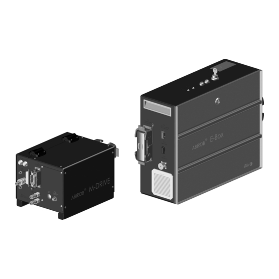
  • Page 48: Caractéristiques Techniques

    2 Description du produit MFS-V2 2.3 Caractéristiques techniques Ø Ø Fig. 1 Dimensions E-Box Fig. 2 Dimensions M-Drive Température ambiante - 10 °C à + 40 °C Transport et stockage - 10 °C à + 55 °C Humidité de l'air relative jusqu'à...
  • Page 49: Description Du Produit

    MFS-V2 2 Description du produit Tension de réseau 230 V / 50 ou 60 Hz Tension de service interne 24 V C.C. Consommation 1,5 kW Classe de protection IP21 Tab. 4 E-Box Support de gaine guide fil pour bobine de fil K 300 mm Câble transport de fil...
  • Page 50: Consignes De Sécurité

    Les pièces d'équipement et d’usure sont à commander séparément. Les caractéristiques et références des pièces d'équipement et d’usure se trouvent dans le catalogue de commande actuel de ABICOR BINZEL. Pour obtenir des conseils et pour passer vos commandes, consultez le site www.binzel-abicor.com.
  • Page 51: Emballage Pour Retour De Marchandise

    Conditions physiques lors du stockage en lieu clos:  Tab. 2 Température page FR-4 5 Description du fonctionnement Le système de dévidoir MFS-V2 est composé d'un E-Box et d'un M-Drive. Le système d'alimentation principal MF contient les composants suivants: M-Drive...
  • Page 52: Mise En Service

    6 Mise en service MFS-V2 6 Mise en service DANGER Risque de blessure causée par un démarrage inattendu Pendant toute la durée des travaux d'entretien, de maintenance, de démontage et de réparation, veiller à ce que • la source de courant soit arrêtée.
  • Page 53: Raccordement Au Réseau

    MFS-V2 6 Mise en service Soufflage sortie Connexion du câble de Entrée Amenée de liquide de Sortie Retour de liquide de Soufflage entrée soudage refroidissement refroidissement Gaz entrée Entrée Retour de liquide de Sortie Amenée de liquide de Faisceau refroidissement refroidissement Fig.
  • Page 54: Enfiler Le Fil

    6 Mise en service MFS-V2 6.5 Enfiler le fil Capot M-Drive Raccord intermédiaire Tube d'entrée Levier de pressionM-Drive 2 basculeurs de pression Galets d'entraînement Coupe-circuit Fig. 8 Enfiler le fil 1 Ouvrir le capot (1) sur le M-Drive (2). 2 Rabattre le levier de pression (2) vers l'avant et ouvrir les basculeurs de pression (4).
  • Page 55: Remplacer Les Galets D'entraînement

    MFS-V2 6 Mise en service 6.6 Remplacer les galets d'entraînement 2 basculeurs de pression 2 arbres de roue 2 vis de fixation Levier de pression 2 galets presseurs 2 galets d'entraînement Fig. 9 Remplacer les galets d'entraînement REMARQUE • Remplacez les galets d'entraînement lorsque le type de fil ou le diamètre de fil a changé ou lorsque les galets d'entraînement sont usés.
  • Page 56: Affectation Des Connecteurs

    6 Mise en service MFS-V2 6.7 Affectation des connecteurs M-Drive E-Box Câble de commande paquet Option terminal manuel Câble de commande E-Box - Câble de commande M-Drive - Interface de programmation robot E-Box Interface module de mémoire Fig. 10 Aperçu de l'affectation des connecteurs...
  • Page 57 MFS-V2 6 Mise en service X46 Broche Description Signaux X47 Broche Encodeur esclave Ch A Encodeur esclave Ch B Transmetteur des valeurs réelles Transmetteur des valeurs réelles Transmetteur de la valeur actuelle Ch A Transmetteur des valeurs réelles Ch B Moteur maître...
  • Page 58: Fonctionnement

    Câble de commande E-Box - robot 7 Fonctionnement REMARQUE • Le système de dévidoir MFS-V2 doit être utilisé uniquement par un personnel qualifié. 7.1 Eléments de commande La clé peut être retirée dans toutes les positions d'interrupteur. FR - 14...
  • Page 59 MFS-V2 7 Fonctionnement Voyant d'état V1 Maître Raccord X47 Câble de connexion avec fiche 13 Raccord Source de courant Touche Reset S4 Câble de commande B M- secteur pour fil chaud Avance de fil S3 Inching Drive Grille d'aération 14 Raccord X43 Câble de Interrupteur à...
  • Page 60: Mise Hors Service

    8 Mise hors service MFS-V2 Symbole Désignation Interrupteur à clé S2 (4) Fig. (11) Auto Etat de commutation Automatique: Dévidoir peut être utilisé sans aucune restriction lorsque le capot est fermé Hand Etat de commutation Manuel: Le dispositif de protection est court-circuité. La fonction Inching (enfiler le fil) est débloquée lorsque le capot (M-Drive) est ouvert.
  • Page 61: Travaux De Nettoyage À Effectuer Chaque Semaine

    MFS-V2 10 Dépannage REMARQUE • Lors des travaux d'entretien et de nettoyage, portez toujours vos vêtements de protection personnels. 9.1 Travaux de nettoyage à effectuer chaque semaine 1 Desserrer le faisceau côté poste et le tendre. 2 Dévisser l'écrou arrêt de gaine et retirer la gaine guide-fil acier ou la gaine guide-fil synthétique.
  • Page 62: Elimination

    (pinceau, chiffon etc.) doivent être également éliminés selon les indications du fabricant des produits consommables. 12.3 Emballages ABICOR BINZEL a réduit l'emballage de transport au nécessaire. Lors du choix des matériaux d'emballage, veiller à ce que ces derniers soient recyclables. 13 Annexe 13.1 Configurations...
  • Page 63: Annexe

    MFS-V2 13 Annexe M-Drive E-Box MF 1/2 Options Commande du robot - E-Box 12 Laser M-Drive - MF 1/2 Source de courant - E-Box 10 Commande du robot 13 Commande du robot - Robot MFS-V2 Source de courant - M-Drive 11 Laser - Commande du robot 14 Laser - Tête laser...
  • Page 64: Support De Bobine

    14 Options MFS-V2 M-Drive E-Box MF 1/2 Câble de commande M-Drive - Source de courant - M-Drive 10 Commande du robot 11 Commande du robot - robot M-Drive - MF 1/2 E-Box Source de courant MFS-V2 Options Commande du robot - E-Box...
  • Page 65: Module De Mémoire

    Le terminal manuel ne doit être utilisé que dans un mode de fonctionnement sans BUS. Le terminal manuel est conçu exclusivement pour le système de dévidoir MFS-V2 et est utilisé pour la commande manuelle du système dans le mode de réglage.
  • Page 66: Activer Le Terminal

    14 Options MFS-V2 14.4.3 Activer le terminal 1 Activer le bouton TM marche/arrêt. Touche Affichage Description Menu principal APD: L'affichage montre que le terminal manuel est activé Terminal manuel activé ! ein/aus Enter 14.4.4 Funktionen Touche Affichage Description Menu principal APD: Ces touches permettent d'écrire un offset dans l'indicateur de la vitesse de fil.
  • Page 67: Menu Service

    MFS-V2 14 Options Touche Affichage Description Menu principal APD: Cette touche permet d'afficher la température actuelle. Selectionner la fonction Heizung Temp. act.=23c La fonction Chauffage est uniquement disponible lorsqu'un module de réglage pour le chauffage est utilisé en option. Menu principal APD: Ces touches permettent de régler la valeur de consigne désirée pour le chauffage.
  • Page 68 Traducción del manual de instrucciones original MFS-V2 Traducción del manual de instrucciones original © El fabricante se reserva el derecho a cambiar este instructivo de servicio sin previo aviso en cualquier momento que esto pudiera ser necesario como resultado de errores de imprenta, errores en la información recibida o mejoras en el producto. Estos cambios, sin embargo, podrían ser tomados en cuenta en posteriores emisiones.
  • Page 69: Identificación

    1 Identificación 1 Identificación La devanadora MFS-V2 se utiliza en la industria y los oficios para el suministro de materiales adicionales de soldadura. Se compone de la caja eléctrica E-Box y M.Drive. La E-Box contiene todos los elementos de mando electrónicos. En el M.Drive está integrado el arrastre por 4 rodillos de la devanadora para la conducción de hilo.
  • Page 70: Datos Técnicos Es

    2 Descripción del producto MFS-V2 2.3 Datos técnicos Ø Ø Fig. 1 Dimensiones de la E-Box Fig. 2 Dimensiones del M.Drive Temperatura ambiente - 10 °C a + 40 °C Transporte y almacenamiento - 10 °C a + 55 °C Humedad relativa del aire Hasta 90 % a 20 °C...
  • Page 71: Descripción Del Producto

    MFS-V2 2 Descripción del producto Consumo 1,5 kW Tipo de protección IP21 Tab. 4 E-Box Sujeción de bobina K 300 mm Conductor de hilo o alambre máx. 6 m Plato aislante Tab. 5 Accesorios 2.4 Abreviaciones MFS-V2 Unidad devanadora (slave y E-Box) para el sistema Master-Feeder Unidad de accionamiento (master) tamaño 1 = diám.
  • Page 72: Instrucciones De Seguridad Es

    Pedir los accesorios y piezas de desgaste por separado. Los datos de pedido y los números de identificación de las piezas de equipo y desgaste pueden leerse en las listas de precios de las piezas de recambio y desgaste de ABICOR BINZEL. Para informaciones sobre el contacto para asesoramiento y pedido ver www.binzel-abicor.com en Internet.
  • Page 73: Control De Entrada

    Condiciones físicas del almacenamiento en un espacio cerrado:  Tab. 1 Declaración de conformidad de la UE en página ES-3 5 Descripción del funcionamiento La devanadora MFS-V2 se compone de E-Box y M.Drive. Los siguientes componentes están incluidos en el sistema Master-Feeder MF: M-Drive...
  • Page 74: Puesta En Servicio Es

    6 Puesta en servicio MFS-V2 6 Puesta en servicio ¡PELIGRO! Peligro de lesiones por arranque inesperado Observar lo siguiente durante todos los trabajos de mantenimiento, servicio, desmontaje y reparación: • Desconectar la fuente de corriente. • Cerrar el suministro de aire comprimido.
  • Page 75: Acoplar Las Conexiones De Medios Al M.drive Es

    MFS-V2 6 Puesta en servicio 6.3 Acoplar las conexiones de medios al M.Drive Acoplar las siguientes conexiones: Salida de soplado Conexión de cable de Entrada de alimentación de Salida de retorno del Entrada de soplado soldadura refrigerante refrigerante Entrada de gas Entrada de retorno del Salida de alimentación de...
  • Page 76: Insertar El Hilo O Alambre Es

    6 Puesta en servicio MFS-V2 6.5 Insertar el hilo o alambre Tapa 2 amarres de presión Tubo de admisión Interruptor de seguridad Palanca de presión Adaptador de distancia M.Drive Rodillos de arrastre Fig. 8 Insertar el hilo o alambre 1 Abrir la tapa (1) del M.Drive (3) 2 Plegar hacia el frente la palanca de presión (2) y abrir los amarres de presión (4).
  • Page 77: Cambiar Los Rodillos De Arrastre Es

    MFS-V2 6 Puesta en servicio 6.6 Cambiar los rodillos de arrastre 2 amarres de presión 2 ejes de quita y pon 2 tornillos de sujeción Palanca de presión 2 rodillos de presión 2 rodillos de arrastre Fig. 9 Cambiar los rodillos de arrastre INDICACIÓN...
  • Page 78: Asignación De Enchufes Es

    6 Puesta en servicio MFS-V2 6.7 Asignación de enchufes M-Drive E-Box Paquete MF de cable de Opción de elemento de Interface de programación able de control M.Drive - E-Box control mando manual Cable de control E-Box - robot Interface del módulo de memoria Fig.
  • Page 79 MFS-V2 6 Puesta en servicio Clavija X46 Descripción Señales X47 Clavija Codificador slave Ch B Transmisor de valor actual Transmisor de valor actual Transmisor de valor actual Ch A Transmisor de valor actual Ch B Motor master Motor master Motor slave...
  • Page 80: Operación Es

    Tab. 11 Cable de control E-Box - robot 7 Operación INDICACIÓN • Sólo especialistas deben operar la devanadora MFS-V2. 7.1 Elementos de mando Se puede extraer la llave en todas las indicaciones de la posición del interruptor. ES - 14...
  • Page 81 MFS-V2 7 Operación Estado LED V1 Master Conexión X47 Cable de conexión con 12 Rejilla de aire Botón Reset S4 Cable de control B M.Drive enchufe de la red 13 Conexión Elemento de mando Avance de hilo o alambre por...
  • Page 82: Puesta Fuera De Servicio

    8 Puesta fuera de servicio MFS-V2 Símbolo Denominación Conmutador con llave S2 (4) Fig. (11) Auto Estado de activación automático: La devanadora está lista para el funcionamiento completo con tapa cerrada Hand (M.Drive). Estado de activación manual: dispositivos de seguridad están puenteados. Funcionamiento por modo de pulsación (insertar hilo o alambre) está...
  • Page 83: Averías Y Su Eliminación

    MFS-V2 10 Averías y su eliminación INDICACIÓN • Llevar siempre la ropa personal de protección laboral durante los trabajos de mantenimiento y limpieza. 9.1 Limpiar semanalmente 1 Soltar el conjunto de cables en el lado de la máquina y colocarlo en posición estirada.
  • Page 84 12.3 Embalajes ABICOR BINZEL ha reducido el embalaje de transporte a un mínimo necesario. Al seleccionar los materiales de embalaje, se tiene en cuenta un posible reciclaje.
  • Page 85 MFS-V2 13 Anexo M-Drive E-Box MF 1/2 Opciones Fuente de corriente de proceso 12 Láser M-Drive - MF 1/2 Fuente de corriente de proceso Control de robot - E-Box 13 Control de robot - robot MFS-V2 - E-Box 10 Control de robot 14 Láser - cabeza láser...
  • Page 86 14 Opciones MFS-V2 M-Drive E-Box MF 1/2 Opciones Fuente de corriente de proceso 11 Control de robot - robot M-Drive - MF 1/2 Fuente de corriente de proceso Control de robot - E-Box 12 Control de robot - Fuente de...
  • Page 87: Módulo De Memoria

    14.4 Elemento de mando manual Utilizar el elemento de mando manual solamente en modo de servicio sin BUS. El elemento de mando manual está diseñado únicamente para la devanadora MFS-V2 y sirve para controlar manualmente el sistema en el modo de ajuste.
  • Page 88: Funciones

    14 Opciones MFS-V2 14.4.3 Activar elemento de mando 1 Accionar botón HT con/des. Botón Indicación en Descripción pantalla Menú principal APD: Indicación en pantalla muestra elemento de mando manual activado. ¡HT activado! ein/aus Enter 14.4.4 Funciones Botón Indicación en Descripción pantalla Menú...
  • Page 89: Menú De Servicio

    MFS-V2 14 Opciones Botón Indicación en Descripción pantalla Menú principal APD: Mediante este botón se muestra la temperatura actual. Elegir función Heizung Temp actual= 23c La función "calefacción" solo es posible con un módulo de regulación de calefacción opcional. Menú principal APD: Mediante estas teclas se ajusta el valor nominal de la calefacción.
  • Page 90 取扱説明書 MFS-V2 取扱説明書 © メーカーは印刷ミス、記載されている情報の不正確さまたは製品の改良により必要となる本取扱説明書の 変更を、常に予告なく行う権利を有します。 しかしながら新しい説明書では、これらの変更は反映されます。 識別 JP- 3 操作 JP- 14 EU 適合宣言 JP- 3 操作要素 JP- 14 使用者の義務 JP- 3 運転停止 JP- 16 製品について JP- 3 使用用途 JP- 3 メンテナンス JP- 16 指定外の用途 JP- 3 週 1 回の手入れ...
  • Page 91: Eu 適合宣言

    ワイヤ送給システム MFS-V2 は、工業・産業部門で溶加材の送給用に使用されます。 E ボッ クスと M ドライブで構成され、 E ボックスにはすべての電子制御要素が、 また、M ドライブ には、ワイヤ送給用の 4 個のローラからなる駆動が内蔵されています。 モジュール設計であ るため、I/O またはデジタルバスシステムにより、個別ケースに機械的、電子的に順応させ ることが可能です。 本取扱説明書では、ワイヤ送給システム MFS-V2 についてのみ説明され ています。 ワイヤ送給システム MFS-V2 には、ABICOR BINZEL の純正スペアパーツのみ使 用できます。 1.1 EU 適合宣言 EC 低電圧指令 2006/95/EC、付属書 III の意味での EU 適合宣言。 これをもって、当社...
  • Page 92: 技術仕様

    2 製品について MFS-V2 2.3 技術仕様 Ø Ø 図 1 E ボックスの寸法 図 2 M ドライブの寸法 環境空気の温度 - 10 °C ~ + 40 °C 輸送と保管 - 10 °C ~ + 55 °C 相対湿度 20 °C で 90 % 以下 表 2 温度...
  • Page 93 2 製品について MFS-V2 入力電圧 230 V / 50 または 60 Hz 内部の動作電圧 24 VDC 消費電力 1,5 kW 保護等級 IP21 表 4 E ボックス ワイヤリールホルダー K 300 mm ワイヤ送給ホース max. 6 m 絶縁板 表 5 アクセサリー 2.4 略称 MFS-V2 マスターフィーダーシステムへのワイヤ送給装置(スレーブと E ボックス)...
  • Page 94 • E ボックスからロボット制御装置への制御配線(片側コネクタ無 し) • 取扱説明書 オプション : リールホルダー K300 手動操作装置 容器入りコイル用ワイヤ送給ホース 各種バスシステム用モジュール メモリモジュール M ドライブ固定用絶縁板 アクセサリー付き熱線電源装置 表 7 納品内容 装備パーツや消耗部品は別注となっています。 装備パーツと消耗部品の発注データと ID 番 号は、最新の ABICOR BINZEL スペアパーツ / 消耗部品価格表をご覧ください。 アドバイス www.binzel-abicor.com や注文のお問い合わせは、インターネット をご覧ください。 4.1 輸送 納品内容は出荷前に入念に検査し梱包してありますが、輸送中の損傷がないとは限りませ ん。 JP - 6...
  • Page 95: E ボックス

    可能な限り、元の梱包箱と元の包装材を利用してください。 材 梱包や輸送中の保全についての質問が生じた場合は、お客様のサプライヤーにご相談ください。 表 8 輸送 4.2 保管 閉じた室内での保管の物理的条件:  表 2 温度 JP- 4 5 機能 ワイヤ送給システム MFS-V2 は、E ボックスと M ドライブで構成されます。 マスターフィー ダーシステム MF には下図の構成要素が含まれます。 M-Drive E-Box MF 1/2 制御線 ケーブルアセンブリ 10 ロボット制御装置 ケーブルアセンブリ M ドライブ - E ボックス...
  • Page 96: 試運転

    6 試運転 MFS-V2 6 試運転 危険 機器が不意に始動することによる傷害の危険 メンテナンス、保守、分解、修理の作業を行うときは、その全期間を通じて、下記の指示 に従ってください。 • 電源を切ってください。 • 圧縮空気の供給を遮断してください。 • 電源プラグを抜いてください。 危険 傷害の危険 手動操作中は、カバーと保護装置の安全スイッチが切れています。 • 細心の注意を払ってください。 警告 挫傷の危険 手足が引き込まれたりつぶされるおそれがあります。 • 回転している車をつかまないでください。 提示 • 試運転は、教育訓練を受けた従業員のみが実施できます。 6.1 据え付け ワイヤのガイドが短く真直になるような据付場所を選んでください。 6.2 制御線を接続する 下図のように制御線を接続してください。 インターフェース X41 インターフェース X47 インターフェース X43 10 制御線...
  • Page 97: M ドライブに媒体を接続する

    6 試運転 MFS-V2 6.3 M ドライブに媒体を接続する 下図に従って接続してください。 ブローエア出口 溶接ケーブルコネクタ 送り冷媒入口 戻り冷媒出口 ブローエア入口 戻り冷媒出口 送り冷媒出口 10 ケーブルアセンブリ ガス供給口 図 7 接続図 6.4 電源への接続 危険 電撃 不良ケーブルによる危険な電圧。 • 適切に配線されているか、すべての電気ケーブルと接続を点検してください。 • 損傷、変形、磨耗のあるパーツは交換してください。 電源ケーブルと電源プラグはすでに取り付けられています。 電源電圧と保護等級は下記参照  2.3 技術仕様 JP- 4  2.5 銘板 JP- 5 1 電源プラグを差し込みます。...
  • Page 98 6 試運転 MFS-V2 6.5 ワイヤの送給方法 カバー 圧力バランス、2 個 駆動ローラ 安全スイッチ 加圧レバー 中間接続部 挿入管 M ドライブ 図 8 ワイヤを通す 1 M ドライブ (3) のカバー (1) を開けます。 2 加圧レバー (2) を前に倒し、圧力バランス (4) を開きます。 3 リールからワイヤの先端部を取り出します。 4 ワイヤを挿入管 (6) に通し、駆動ローラ (5) に掛けて中間接続部 (5) に差し込みます。...
  • Page 99: ワイヤの送給方法 Jp

    6 試運転 MFS-V2 6.6 駆動ローラの交換方法 圧力バランス、2 個 差込軸、2 本 押さえねじ、2 個 加圧レバー 加圧ローラ、2 個 駆動ローラ、2 個 図 9 駆動ローラを交換する 提示 • ワイヤの種類や直径が変わった時、また、駆動ローラに磨耗が生じた時は、必ず駆動 ローラを交換してください。 • 駆動ローラは、必ずペアで交換または裏返してください。 • 溝の形状とワイヤ直径に注意してください。 必要に応じて、ワイヤを切断し、そのあとで通し直してください。  6.5 ワイヤの送給方法 JP- 10 以下の手順を実施してください。 1 M ドライブのカバーを開けます。 2 加圧レバー (5) を前に倒します。...
  • Page 100: コネクタの配置

    6 試運転 MFS-V2 6.7 コネクタの配置 M-Drive E-Box 制御線 MF パッケージ オプションの手動操作装置 制御線 E ボックス - ロ 制御線 M ドライブ - E ボッ メモリモジュール用イン プログラミングインター ボット クス ターフェース フェース 図 10 コネクタ配置図 ピン 説明 信号 X41 ピン ロータリエンコーダ ロータリエンコーダ ロータリエンコーダ スタンバイ...
  • Page 101 6 試運転 MFS-V2 X46 ピン 説明 信号 X47 ピン エンコーダ スレーブ チャンネル B 実際値伝送器 実際値伝送器 実際値伝送器 チャンネル A 実際値伝送器 チャンネル B モータ マスター モータ マスター モータ スレーブ モータ スレーブ 端子盤 24V インチング / 初期化 / 後進用 B9 インチング スイッチ ON、フィードバック...
  • Page 102: 操作要素

    24V スイッチ ON 準備完了、In 準備完了、Out リセット リセット 24V スイッチ ON インチング インチング 24V スイッチ ON 接地回路監視 接地回路監視 ワイヤ速度実際値 0 ... 10V ワイヤ速度実際値 表 11 制御線 E ボックス - ロボット 7 操作 提示 • ワイヤ送給システム MFS-V2 を操作できるのは、専門職のみに限定されています。 7.1 操作要素 キーは、どのスイッチポジションでも抜くことができます。 JP - 14...
  • Page 103 7 操作 MFS-V2 マスターの状態表示 LED V1 ソケット X47 電源プラグ付き接続ケーブ 12 ファンガード リセットボタン S4 M ドライブ制御線 B ル 13 熱線電源装置からのソケッ ワイヤ前進インチング S3 メインスイッチ Q1 ファンガード ト 自動 / 手動切替キースイッ 電源装置からの制御線 E 用 10 サービスインターフェース 14 ロボット制御線 C 用ソ チ S2 ソケット X51 ケット...
  • Page 104: 運転停止

    8 運転停止 MFS-V2 シンボル 名称 キースイッチ S2 (4) 図 (11) Auto スイッチポジション Auto: M ドライブのカバーが閉じた状態で、ワイヤ送給装置の機能が無制限に Hand 可能 スイッチポジション Hand: 保護装置がブリッジされ、 M ドライブのカバーを開けた状態で、ワイヤ を通すインチング機能を実行できるようになります。 そのほかのあらゆる可能な状況で、駆動装置 への通電が止められスタート信号が遮断されたままになります。 インチング押しボタン S3 (3) または 図 (11) の S7 (5) 図 (12) 押しボタンを押すと、ワイヤが送られます。 初期化ボタン S4 (2) または図 (11) の S9 (16) 図 (12) トラブルシューティングのあと、このボタンを押します。...
  • Page 105: 週 1 回の手入れ

    10 トラブルシューティング MFS-V2 提示 • メンテナンスと手入れの作業は、有資格の教育訓練を受けた専門職にのみ実施すること が許されています。 • メンテナンスと手入れの作業中は、必ずご自分の防護服を着用してください。 9.1 週 1 回の手入れ 1 ケーブルアセンブリを機械側から外し、伸ばした状態にします。 2 ユニオンナットを外し、ガイドスパイラルまたはプラスチックの芯を抜きます。 警告 傷害の危険 圧縮空気によってパーツ等が飛散して負傷を負う危険があります。 ワイヤガイドにエアを吹き付けるときは、適切な防護服、特に保護眼鏡を着用してくださ い。 3 ワイヤ送給ホースの両側から圧縮空気を吹き付けます。 4 ホースに合わせたガイドスパイラルもしくはプラスチックの芯をワイヤ送給ホースに挿 入し、ユニオンナットで固定します。 9.2 月 1 回の手入れ すべての可動部品とローラの軸受に適切な潤滑油を注油します。 9.3 3ヵ月に 1 回の手入れ E ボックス内の両方のエアフィルタを点検、掃除し、必要に応じて交換します。 10 トラブルシューティング...
  • Page 106: 廃棄処理

    • 溶接設備全体のスイッチを切ってください。 • 電源プラグを抜いてください。 提示 • 8 運転停止 JP- 16 の情報を参照してください。 1 ワイヤ送給装置からケーブルアセンブリを外します。 2 取り外せるパーツ(交換パーツ、ホルダー、ロボットマウント CAT、トーチネック)を取 り外します。 12 廃棄処理 廃棄処理に当たって、国や地方の規定、法律、規則、規格、指令などを守ってください。 ワイヤ送給システム MFS-V2 を適切に廃棄処理するために、まず分解する必要があります。  11 分解 JP- 18 参照 12.1 材料 本製品は、大部分がプラスチック、スチール、非鉄金属でできています。 スチールと非鉄金 属は、製鋼所や製錬所で再び溶かすことができるため、ほとんど無制限に再利用できます。 使用されているプラスチック類は識別表示され、のちのリサイクルに向けて、材料の分別、 分留ができるよう準備されています。 12.2 運転用材料 オイル、グリース、洗浄剤は、土壌を汚染したり、下水道に侵入してはなりません。 これら...
  • Page 107 13 付記 MFS-V2 M-Drive E-Box MF 1/2 オプション プロセス電源装置 12 レーザ M ドライブ - MF 1/2 プロセス電源装置 - E ボッ ロボット制御装置 - E ボッ 13 ロボット制御装置 - ロ MFS-V2 クス クス ボット 制御線 M ドライブ - E ボッ プロセス電源装置 - M ドラ...
  • Page 108: オプション

    14 オプション MFS-V2 M-Drive E-Box MF 1/2 オプション プロセス電源装置 11 ロボット制御装置 - ロ M ドライブ - MF 1/2 プロセス電源装置 - E ボッ ロボット制御装置 - E ボッ ボット MFS-V2 クス クス 12 ロボット制御装置 - プロ 制御線 M ドライブ - E ボッ...
  • Page 109: メモリモジュール

    伝送に約 1 分 30 秒かかります。 データ伝送が無事終了すると、緑の状態表示 LED が点灯し ます。 4 メインスイッチで E ボックスのスイッチを切ります。 5 メモリモジュールを抜きます。 6 メインスイッチで E ボックスのスイッチを入れます。 これで、プログラムが読み込まれ、 E ボックスと M ドライブは準備完了状態になりました。 14.4 手動操作装置 手動操作装置は、バス無しで運転する際にのみ使用してください。 本手動操作装置はワイヤ送給システム MFS-V2 用にのみ考案されたもので、段取運転中に システムを手動で操作するために利用されます。 14.4.1 特徴 設定目標値のオフセット(ワイヤ速度) 0...10V 駆動 スタート 駆動 ストップ 後進 インチング 前進(ワイヤを通す)...
  • Page 110: 手動操作装置のアクティブ化

    14 オプション MFS-V2 14.4.3 手動操作装置のアクティブ化 1 キー手動操作装置 on/off を押します。 キー ディスプレイの表示 説明 APD メインメニュー : ディスプレイに手動操作装置がアクティブ化されたことが表示され 手動操作装置アクティブ ! ます ein/aus Enter 14.4.4 機能 キー ディスプレイの表示 説明 APD メインメニュー : このキーにより、ワイヤ速度のオフセット値がマーカに記入されま plus 機能の選択 す。 ワイヤ速度は、0 ~ 10 V の間で目標値を設定できます。 Sollwert ワイヤ速度 = 0.0 m/min...
  • Page 111: サービスメニュー

    14 オプション MFS-V2 キー ディスプレイの表示 説明 APD メインメニュー : このキーにより、現在の温度が表示されます。 機能の選択 Heizung 現在温度 = 23 ℃ 機能「ヒータ」は、オプションのヒータ制御モジュールが付いている場合にのみ利用できます。 APD メインメニュー : このキーにより、ヒータの目標値を設定します。 plus 機能の選択 Heizung 現在温度 = 23 ℃ 目標値 = 27 ℃ minus Heizung 機能「ヒータ」は、オプションのヒータ制御モジュールが付いている場合にのみ利用できます。 14.4.5 サービスメニュー サービスメニューのナビゲーションは、矢印キーと数字キーを使って行い、エンターキー で確定します。 キー...
  • Page 112 使用说明 MFS-V2 使用说明 © 如果由于产品的改进,印刷错误或不准确,制造商有权在任何时 候、且不作预先通知的情况下修正或更改此 《操作说明书》 。然 而,这些修改将会作为 《说明书》的后续版本的组成部分 识别鉴定 ZH- 3 操作 ZH- 13 欧盟符合性说明 ZH- 3 操作单元 ZH- 13 使用方的责任 ZH- 3 停用 ZH- 14 产品介绍产品介绍 ZH- 3 合理使用 ZH- 3 维护和清洗 ZH- 14 非合理使用 ZH- 3 每周清洗...
  • Page 113: 识别鉴定

    1 识别鉴定 焊丝输入装置 MFS-V2 用于工业领域内焊接附加材料的输送。 装置包括主控制箱和主驱动 箱。 主控制箱内有全部电气控制元件,主驱动箱包括送丝用的 4 滚子驱动装置。 块结构的好 处在于,可以通过 E/A 或者 BUS 总线进行个性化机械和电子匹配。 本使用说明是关于焊丝输 入装置 MFS-V2。 MFS-V2 焊丝输入装置只允许使用 ABICOR BINZEL 原配件操作。 1.1 欧盟符合性说明 根据欧共体低压规章 2006/95/EG。 我们特此声明 , Alexander BINZEL Schweisstechnik GmbH & Co. KG Kiesacker 7-9, 35418 Alten-Buseck 使用说明所含的...
  • Page 114 2 产品介绍产品介绍 MFS-V2 插图 2 M-Drive 驱动 尺寸 作业环境气温 - 10 °C 至 + 40 °C 运输和存贮 - 10 °C 至 + 55 °C 空气相对湿度 不超过 90 % 在 20 °C 时 表格 2 温度 重量 约 13 kg 供电电压...
  • Page 115 3 安全须知 MFS-V2 驱动单元 ( 主 ) 结构尺寸 2 = 辊子 -ø 30 mm VTS, ABK, WH 导丝管接口 等离子体驱动 等离子焊枪驱动 复合 - 激光 激光驱动 / MIG 焊接 E-Box 箱 组件包括电子部件 M-Drive 驱动 送丝驱动带出入接口 表格 6 缩写 2.5 铭牌 M-Drive 主驱动箱 和 E-Box 主控制箱 用一个铭牌标识如下 : Alexander Binzel Schweisstechnik GmbH &...
  • Page 116: 紧急情况

    • 篮形线圈 K300 的线圈支架 • 手动终端 • 桶线圈用送丝管 • 不同 BUS 总线系统用模块 • 记忆模块 • M-Drive 固定用绝缘板 • 热丝电源 带附件 表格 7 供货范围 专门订购装配和耗损部件。 订货所需信息和货品号码参见最新 ABICOR BINZEL 备件及磨损 件价目表。 咨询和订购的联系方式在线请查 www.binzel-abicor.com 。 4.1 运输 所有供货由发货部门仔细检验和包装。尽管如此,不能排除运输途中不发生损坏。 进货检验 请查验数量是否符合交货单 ! 出现损坏 检查到货是否出现损坏 ( 视觉检查 )! 投诉...
  • Page 117: 功能介绍

    5 功能介绍 MFS-V2 5 功能介绍 装置 MFS-V2 包括 E-BoxE 主控制箱 和 M-Drive 主驱动箱。 主输入系统 MF 包括以下部分 : M-Drive E-Box MF 1/2 控制电缆 软管组件 10 机器人控制 软管组件带控制电缆 M-Drive - E-Box 作业电源 - M-Drive 11 控制电缆 M-Drive - MF 1/2 可选 作业电源...
  • Page 118: 接通控制电缆

    6 启用 MFS-V2 提示 • 系统的启用须由受过培训的人员完成。 6.1 固定 选择地点时,须注意焊丝能够短途直线输导。 6.2 接通控制电缆 按如下方式接通控制电缆 : 接口 X41 接口 X48 接口 X43 12 控制电缆 E 接口 X46 接口 X49 10 E-Box 箱 13 M-Drive 驱动 控制电缆 B 控制电缆 C 11 接口 X51 14 控制电缆 A 接口...
  • Page 119 6 启用 MFS-V2 电源电缆和电源插销已安装。 电源电压和保护参见 :  2.3 技术数据 ZH- 3  2.5 铭牌 ZH- 5 1 插入电源插销。 6.5 焊丝导入 盖子 M-Drive 驱动 中间接口 喂入管 压力杆 2 个压力套 驱动辊子 安全开关 插图 8 焊丝导入 1 把盖子 (1) 在 -Drive(2) 打开。 2 压力杆 (2) 向前搬动,将压力套 (3) 打开。...
  • Page 120: 焊丝导入 Zh

    6 启用 MFS-V2 6.6 更换驱动辊子 2 个压力套 2 个法兰半轴 2 个固定螺销 压力杆 2 个压辊 2 个驱动辊子 插图 9 更换驱动辊子 提示 • 出现以下情况须更换驱动辊子 : 当焊丝种类,焊丝直径变化,或者当驱动辊子耗损时。 • 须成对更换或翻转驱动辊子。 • 注意槽尺寸和焊丝直径。 必要时,断开焊丝,重新导入。  6.5 焊丝导入 ZH- 9 1 把盖子 在 M-Drive 打开。 2 把压力杆 (5) 向前搬动。...
  • Page 121: 接插分布

    6 启用 MFS-V2 6.7 接插分布 M-Drive E-Box 控制电缆 MF-Paket 可选 手动终端 控制电缆 E-Box - 机器人 控制电缆 M-Drive - E-Box 接口 记忆模块 程序接口 插图 10 接插分布 概览 针 描述 信号 X41 针 编码器 编码器 编码器 Stby 编码器 Ch A 编码器 Ch B 键控器...
  • Page 122 6 启用 MFS-V2 X46 针 描述 信号 X47 针 实际值传感器 实际值传感器 Ch A 实际值传感器 Ch B 马达 主 马达 主 马达 从 马达 从 接线板 24V 微调 / 复位 / 回程 微调 开到 返回 复位 开到 返回 微调 回程 开到 返回...
  • Page 123: 操作单元

    接地监控 接地监控 焊丝实际值 0 ... 10V 焊丝实际值 表格 11 控制电缆 E-Box - 机器人 7 操作 提示 • 焊丝输入装置 MFS-V2 的操作须由专业人员完成。 7.1 操作单元 您可以在任何开关状态拔出钥匙 . 状态 LED V1 主 连接 X47 连接电缆带电源插销 13 连接 手动终端 复位 键控器 S4 控制电缆 B M-Drive 空气栅...
  • Page 124: 维护和清洗

    8 停用 MFS-V2 气体测试 S8 焊丝推进 微调 S7 10 电流接口 14 插销 X41 控制电缆 软管组 连接 吹气风 焊丝喂入 11 数字编码器 X59 件 气接口 冷却剂推进 12 冷却剂返回 15 主插座 ZL 带气体接口 插销 X46 控制电缆 冷却剂返回 13 冷却剂推进 16 复位 - 键控器 S9 连接...
  • Page 125: 每周清洗

    10 干扰和排除 MFS-V2 危险 电振 电缆故障造成危险电压。 • 检查所有带电线缆和连接是否安装正确。 • 更新受损,变形和耗损的部件。 警告 挤压危险 四肢被卷入挤碎。 • 不可伸入转动车轮。 提示 • 建议的维护间隔作为参考,是根据一个班作业的。 • 维护和清洗工作必须由受过培训的专业人员完成。 • 进行维护和清洗工作时须穿戴个人防护衣。 9.1 每周清洗 1 摘下软管组件 并展开。 2 取下中继螺母 , 螺旋管和塑料芯。 警告 损伤危险 摇摆部分可能引发严重危险。 • 使用压缩气打扫送丝软管时须穿戴防护衣,尤其防护眼镜。 3 使用压缩气将送丝管两侧吹净。 4 将调节好的螺旋管和塑料芯推入送丝管并用中继螺母固定。...
  • Page 126: 废物处理

    12 废物处理 废物处理须遵守当地有关法律,法规,规定,标准和方针。 为了正确进行废物处理,您必须 首先拆散该产品。  见 11 拆散 ZH- 16 12.1 原料 本产品主要原料为钢和有色金属 , 可以回收,并重新使用。 对采用的塑料进行了标识,以便 于将来回炉处理时的材料分类。 12.2 辅助材料 润滑油脂和清洗剂不可进入地下或者排水系统。 这些物质须使用适当的容器存放,运输和处 理。 注意遵守当地的有关规定和辅助材料生产商提供的相关处理指示。 受污染的清洗工具 ( 毛刷 , 抹布等 ) 也必须按照生产商的指示进行处理。 12.3 包装 ABICOR BINZEL 尽量减少运输包装。 包装材料尽量采用可回收再生材料。 ZH - 16...
  • Page 127 13 附件 MFS-V2 13 附件 13.1 配置 使用激光热丝设置时,您需要工作电源用于热丝。 M-Drive E-Box MF 1/2 可选 机器人控制 - E-Box 12 激光 M-Drive - MF 1/2 作业电源 - E-Box 10 机器人控制 13 机器人控制 - 机器人 MFS-V2 作业电源 - M-Drive 11 激光 - 机器人控制 14 激光 - 激光头...
  • Page 128: 线圈架

    14 可选 MFS-V2 M-Drive E-Box MF 1/2 控制电缆 M-Drive - E-Box 作业电源 - M-Drive 10 机器人控制 M-Drive - MF 1/2 可选 作业电源 11 机器人控制 - 机器人 MFS-V2 作业电源 - E-Box 机器人控制 - E-Box 12 机器人控制 - 作业电源 插图 15 复合焊接...
  • Page 129: 记忆模块

    4 通过中央开关关闭 E-Box。 5 拔出记忆模块 Memory Modul。 6 通过中央开关打开 E-Box。 程序安装成功。 E-Box 和 M-Drive 待命工作。 14.4 手动终端 只有在无 BUS 总线工作模式时才能使用手动终端。 手动终端是专为焊丝输入装置 MFS-V2 设计的,用于单班作业的手动系统控制。 14.4.1 特征 • 规定额定值 补偿 ( 送丝速度 ) 0...10V • 驱动 起动 • 驱动 停止 • 回程 (Reverse) •...
  • Page 130 14 可选 MFS-V2 14.4.4 功能 键控器 显示屏 描述 APD- 主菜单 : 通过此键往记忆模块输入送丝速度的补偿值。 送丝速度的设定范围在额定 plus 功能选择 值 0 - 10 V 之间。 Sollwert DG= 0.0 m/ 分钟 ADoffset= 5.0V minus Sollwert 输入的补偿值不会因为开关 E-Box 被删除。 APD- 主菜单 : 操作此键起动已设定的驱动装置。如果安装了可选的焊丝实际值传感器, 驱动 起动 ! 显示屏显示送丝速度。...
  • Page 131: 服务 菜单

    14 可选 MFS-V2 键控器 显示屏 描述 加热功能只限于可选的加热调节模块。 14.4.5 服务 菜单 服务菜单内的导航通过方向键和数字键,按确认键确认。 键控器 显示屏 描述 服务菜单 : 操作此键进入服务菜单。 => 返回 Service 测轮 版本 测轮 - 参数 : 通过测轮对可选焊丝实际值传感器进行设置。 直径 = 10.0 EncLin= 1024 辊子标准直径为 10,0 毫米。 编码器的标准网目线数为 1024。 通过版本选项显示所有软件版本。 版本 : E-Box 手动终端...
  • Page 132 T E C H N O L O G Y F O R T H E W E L D E R ´ S W O R L D . Alexander Binzel Schweisstechnik GmbH & Co.KG Postfach 10 01 53 • D–35331 Giessen Tel.: ++49 (0) 64 08 / 59–0 Fax:...

Table des Matières