Table des Matières

Publicité

Les langues disponibles

Les langues disponibles

Liens rapides

LCD Data Projector
Operating Instructions
Mode d'emploi
Manual de instrucciones
VPL-PX20
VPL-PX30
© 1999 Sony Corporation
4-073-984-12(1)
GB
FR
ES

Publicité

Table des Matières
loading

Sommaire des Matières pour Sony VPL-PX20

  • Page 1 4-073-984-12(1) LCD Data Projector Operating Instructions Mode d’emploi Manual de instrucciones VPL-PX20 VPL-PX30 © 1999 Sony Corporation...
  • Page 2 • When the Remote Commander causes malfunction, which case the user will be required to correct the consult with qualified Sony personnel. We change the interference at his own expense. Remote Commander as new one according to the guarantee.
  • Page 3 For the customers in Canada This Class A digital apparatus complies with Canadian ICES-003. For the customers in the United Kingdom WARNING THIS APPARATUS MUST BE EARTHED IMPORTANT The wires in this mains lead are coloured in accordance with the following code: Green-and-Yellow: Earth Blue: Neutral...
  • Page 4 (GB)
  • Page 5: Table Des Matières

    Table of Contents Overview Precautions ............... 7 (GB) Features ..............8 (GB) Location and Function of Controls ......9 (GB) Front/Left Side ............9 (GB) Rear/Right Side/Bottom ........... 9 (GB) Control panel ............11 (GB) Connector panel ............. 12 (GB) Remote Commander ..........
  • Page 6 Maintenance Maintenance ............32 (GB) Replacing the Lamp ..........32 (GB) Cleaning the Air Filter ........... 33 (GB) Troubleshooting ............. 34 (GB) Other Specifications ............36 (GB) Index ................ 42 (GB) (GB)
  • Page 7: Precautions

    Precautions On preventing internal heat build-up Precautions After you turn off the power with the I / 1 key on the Remote Commander or on the control panel, do not On safety disconnect the unit from the wall outlet while the cooling fan is still running.
  • Page 8: Features

    Remote Commander. lamp allow high brightness (light output 1400 ANSI • Digital ZOOM, FUNCTION and HELP keys on lumen for VPL-PX20, and 2400 ANSI lumen for the Remote Commander VPL-PX30) and excellent uniformity on the picture. The Digital ZOOM allows you to enhance your •...
  • Page 9: Location And Function Of Controls

    Location and Function of Controls 1 Zoom ring Location and Function of Adjusts the size of the picture. Controls 2 Focus ring Adjusts the picture focus. Front/Left Side 3 Lens Open the lens cap before projection. 4 Ventilation holes (exhaust) 5 Front remote control detector (SIRCS receiver) 6 Adjuster When a picture is projected on the out of the screen,...
  • Page 10 Location and Function of Controls qg Rear speaker How to use the adjuster qh Lamp cover To adjust the height qj Ventilation holes (intake)/air filter cover Adjust the height of the projector as follows: Notes Lift the projector and press the adjuster buttons. •...
  • Page 11: Control Panel

    Location and Function of Controls Control panel • Lights in green when the power is turned on. • Flashes in green while the cooling fan runs after turning off the power with the I / 1 key. The fan runs for about 120 seconds after turning off LAMP/ TEMP/ POWER...
  • Page 12: Connector Panel

    , G/Y, B/B- output) jack , SYNC/HD, VD connectors) (BNC type): Connects to the control S out jacks of the Sony equipment. Connects to the CONTROL S OUT jack on the supplied Connect to a high-resolution computer or VCR Remote Commander when using it as a wired Remote where signals are transmitted long distances;...
  • Page 13: Remote Commander

    Location and Function of Controls 6 Joy stick 6 OUTPUT connectors MONITOR (HD D-sub 15-pin, female): Connects Functions as a mouse of a computer connected to the unit. to the video input connector on the monitor. Outputs signals from the selected channel in the 7 Arrow keys (M/m/</,) INPUT A (RGB or 5BNC) or INPUT B (RGB) 8 L CLICK key...
  • Page 14: Battery Installation

    Location and Function of Controls / Installing the Projector qj MUTING keys Installing the Projector Cut off the picture and sound. PIC: Cuts off the picture. Press again to restore the picture. This section describes the installation arrangements AUDIO: Cuts off the sound from speakers and for installing the projector.
  • Page 15: Connecting

    Connecting • insert the plugs of the cables properly; plugs that are Connecting not fully inserted often generate noise. When pulling out a cable, be sure to pull it out from the plug, not the cable itself. Connecting with a Computer This section describes how to connect the projector to Notes a computer.
  • Page 16 Connecting Using the DIGITAL RGB (TMDS) When connecting with a Macintosh connector computer Connect the computer to the DIGITAL RGB (TMDS) DIGITAL connector on the connector panel. Right side 5BNC REMOTE CONTROL S VIDEO IN (MONO) DIGITAL RS-232C S VIDEO VIDEO AUDIO PLUG IN POWER...
  • Page 17: Connecting With A Vcr/15K Rgb/Component Equipment

    Connecting USB hub function Using USB equipment (e.g., USB mouse) If you connect the projector and your computer using the USB cable for the first time, the following devices Connect the USB equipment to the USB connector on will be recognized. the connector panel.
  • Page 18: Selecting The Menu Language

    Connecting / Selecting the Menu Language Selecting the Menu Language Right side You can select the language for displaying in the DIGITAL menu and other on screen displays. The factory setting 5BNC is ENGLISH. REMOTE CONTROL S VIDEO IN (MONO) LAMP/ TEMP/ POWER...
  • Page 19: Projecting

    Projecting INPUT-B: Selects audio and video signals input Projecting from the INPUT B connector. VIDEO: Selects audio and video signals input from the AUDIO/VIDEO (VIDEO IN) jacks. S-VIDEO: Selects audio and video signals input from the AUDIO/S VIDEO (VIDEO ON/STANDBY indicator IN) jacks.
  • Page 20 Projecting • “ADJUSTING” appears on the screen. Press the To turn off the power APA key again during the adjustment to restore the original screen. Press the I / 1 key. • “Complete!” appears on the screen when the picture is adjusted properly.
  • Page 21: Effective Tools For Your Presentation

    Projecting Effective tools for your presentation To enlarge the image (Digital Zoom function) You can select a point in the image to enlarge. Press the D ZOOM + key on the Remote Commander. The Digital Zoom icon appears at the center of the image.
  • Page 22: Using The Menu

    Using the MENU / The PICTURE CTRL Menu About the memory of the settings Using the MENU The projector is equipped with an on-screen menu for The settings are automatically stored in the projector making various adjustments and settings. memory. To select the language used in the menu, see page 26 (GB).
  • Page 23 The PICTURE CTRL Menu To decrease the number, press the m or < key. GAMMA MODE Press the ENTER key to restore the original screen. Selects a gamma correction curve. • When changing the setting: GRAPHICS: Improves the reproduction of half Press the M or m key to change the setting.
  • Page 24: The Input Setting Menu

    The INPUT SETTING Menu SIZE H The INPUT SETTING Menu The INPUT SETTING menu is used to adjust the Adjusts the horizontal size of picture input from the input signal. INPUT A/B connector. The higher the setting, the larger the horizontal size of Unadjustable items depending on the input signal are the picture.
  • Page 25: Input Signals And Adjustable/Setting Items

    The INPUT SETTING Menu Input signals and adjustable/setting items Preset signals Memory Preset signal Sync SIZE Item Input signal (kHz) (Hz) Video or 15k RGB/ HDTV B&W Video 60 Hz 15.734 59.940 H-neg V-neg S video (Y/C) Component Video 50 Hz 15.625 50.000 H-neg V-neg –...
  • Page 26: The Set Setting Menu

    For details on the warning messages, see page 35 (GB). SGI-1 1320 Macintosh 19” 1328 Macintosh 21” 1456 INPUT-A Sony News 1708 PC-9821 1600 Selects the computer, component, DTV YP 1280 × 1024 DTV GBR signal input from the 5BNC connector. WS Sunmicro...
  • Page 27: The Install Setting Menu

    The SET SETTING Menu/The INSTALL SETTING Menu KEYSTONE MEM POWER SAVING ON: DIGIT KEYSTONE setting is stored. When set to ON, the projector goes into the power The data is retrieved when the projector power is saving mode if no signal is input for 10 minutes. turned on.
  • Page 28: Installation Examples

    Installation Examples Installation Examples Floor Installation a: Distance between the screen and the center of the lens b: Distance from the floor to the center of the lens c: Distance from the floor to the foot of the projector x: Free Distance from the front of the cabinet and the center Wall...
  • Page 29: Ceiling Installation

    Installation Examples Ceiling Installation When installing the projector on the ceiling, use the For ceiling installation, consult with qualified Sony PSS-610 Projector Suspension Support. personnel. a: Distance between the screen and the center of the lens b: Distance between the ceiling and the center of the lens...
  • Page 30: Tips For Installation

    U V W U Tips for Installation Very dusty Tips for Installation Unsuitable Installation Do not install the projector in the following situations. These installations may cause malfunction or damage Avoid installing the unit in a location where there is a to the projector.
  • Page 31 Tips for Installation No blocking the ventilation holes Avoid using something to cover over the ventilation holes; otherwise, the internal heat may build up. (GB)
  • Page 32: Maintenance

    Philips screwdriver (supplied with the LMP- P200 Projector Lamp). Notes • If the lamp breaks, consult with qualified Sony personnel. • Pull out the lamp unit by holding the handle. If you touch the lamp unit, you may be burned or injured.
  • Page 33: Cleaning The Air Filter

    Maintenance Close the lamp cover and tighten the screw. Peel off the air filter. (The air filter is secured with Velcro tape (3).) Turn the projector back over. Connect the power cord and turn the projector to the standby mode. Press the following keys on the control panel in the following order for less than in five seconds each: RESET, <, ,, ENTER.
  • Page 34: Troubleshooting

    • Image: A menu is not displayed. Colors are not correct. • Sound: Sound is not output correctly. • Other: The indicator lights up/flashes. If you still have a problem after consulting the help messages, please check the following. If the problem persists, contact your Sony dealer. Power Symptom Remedy Cause The power is not turned on.
  • Page 35 Wait for 120 seconds to cool down the lamp and turn on the power again (see page 19 (GB)) . The TEMP/FAN indicator The fan is broken. Consult with qualified Sony personnel. flashes. The TEMP/FAN indicator The internal temperature is unusually Check to see if nothing is blocking the ventilation lights up.
  • Page 36: Specifications

    Tweeter: 45 mm (1 inches) diameter, max. 1 W × 2 (stereo) Projection system 3 LCD panels, 1 lens, projection system LCD panel VPL-PX20: 1.3-inch TFT SONY Input/Output LCD panel VPL-PX30: 1.3-inch TFT SONY LCD panel with micro-lens Video/audio input VIDEO: phono type array, Composite video: 1 Vp-p ±2 dB...
  • Page 37 Specifications G: 0.7 Vp-p ±2 dB (75 ohms R/R-Y,G/Y,B/B-Y: Gain terminated) Unity,75ohms G with sync/Y: 1 Vp-p ±2 dB SYNC/HD,VD: 4Vp-p (open), sync negative (75 ohms 1Vp-p (75ohms) terminated) * DIGITAL RGB signal is not B/B-Y: 0.7 Vp-p ±2 dB (75 output from MONITOR OUT ohms terminated) terminal.
  • Page 38: Optional Accessories

    Some of the items may not be available in some areas. For details, please consult your nearest Sony office.......................................... 1) VLC-600 and VPS-50C may not be available in some areas. For details, please consult your nearest Sony office. (GB)
  • Page 39 Specifications DIGITAL RGB input connector (DFP 20-pin, Mouse cable pin assignment female) SIC-S21 13-pin D-sub 9-pin TX0– TXC– TX0+ TXC+ 98/AT/TXD TX0 SHIELD TXC SHIELD +5V/DTR TX2 SHIELD TX1 SHIELD CLOCK TX2– TX1– DATA TX2+ TX1+ DDC/SCL L/PS DDC/SDA SENSE +5V DC SIC-S22 USB connector...
  • Page 40: Dimensions

    Specifications Dimensions Front 339 (13 142 (5 55 (2 ) 64.3 (2 58 (2 16.6( 82 (3 Center of the lens Center of the unit 248 (9 99 (3 105 (4 Unit: mm (inches) (GB)
  • Page 41 Specifications Side 28.4 35.4 146 (5 0 – 2.1 (0 – 45.4 335.5 (13 Bottom 279 (10 26.5 (1 82.5 (3 117.2 (4 7.2 ( 81.5 (3 54.5 108.8 113.5 96 (3 Center of the unit Unit: mm (inches) (GB)
  • Page 42: Index

    Index I, J, K Index INPUT-A 26 (GB) Remote Commander INPUT SETTING menu 24 (GB) battery installation 14 (GB) INSTALL SETTING menu 27 (GB) D ZOOM key 13 (GB), 21 (GB) FUNCTION key 13 (GB) INSTALLATION 27 (GB) Adjuster 10 (GB) Installation examples 28 (GB) HELP key 14 (GB) Adjusting...
  • Page 43 (GB)
  • Page 44 • En cas de problème avec la télécommande, adressez- Cette étiquette est vous à un personnel Sony qualifié. Nous remplaçons la apposée sur le côté de la télécommande par une neuve conformément aux termes télécommande.
  • Page 45: Présentation

    Table des matières Présentation Précautions ..............5 (FR) Caractéristiques ............6 (FR) Emplacement et fonction des commandes ..... 7 (FR) Avant/Côté gauche ............ 7 (FR) Arrière/Côté droit/Dessous ........7 (FR) Panneau de commande ..........8 (FR) Panneau des connecteurs ........10 (FR) Télécommande ............
  • Page 46 Entretien Entretien ..............31 (FR) Remplacement de la lampe ........31 (FR) Nettoyage du filtre à air .......... 32 (FR) Dépannage ............... 33 (FR) Divers Spécifications ............35 (FR) Index ................. 41 (FR) (FR)
  • Page 47: Précautions

    Précautions Prévention de la surchauffe interne Précautions Après avoir mis l’appareil hors tension au moyen de la touche I / 1 de la télécommande ou du panneau de Sécurité commande, ne débranchez pas l’appareil de la prise secteur tant que le ventilateur de refroidissement •...
  • Page 48: Caractéristiques

    élevée (puissance de sortie de 1400 lumens ANSI Vous pouvez assigner un fichier de présentation aux pour le VPL-PX20 et de 2400 lumens ANSI pour le touches FUNCTION à l’aide du logiciel VPL-PX30) et une excellente uniformité de l’image.
  • Page 49: Emplacement Et Fonction Des Commandes

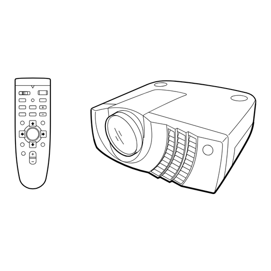
    Emplacement et fonction des commandes 1 Bague de zoom Emplacement et fonction Ajuste la taille de l’image. des commandes 2 Bague de mise au point Ajuste la mise au point de l’image. Avant/Côté gauche 3 Objectif Ouvrez le volet de l’objectif avant la projection. 4 Orifices de ventilation (sortie d’air) 5 Capteur de télécommande frontal (récepteur SIRCS)
  • Page 50: Panneau De Commande

    Emplacement et fonction des commandes qg Haut-parleur arrière Tout en appuyant sur les boutons, abaissez le projecteur. Ensuite, relâchez les boutons. qh Couvercle de la lampe Pour un réglage fin, tournez les dispositifs de réglage vers la droite et vers la gauche. qj Orifices de ventilation (prise d’air)/couvercle du filtre à...
  • Page 51 Emplacement et fonction des commandes 6 Touche I / 1 (marche / veille) 5 Indicateurs LAMP/COVER: S’allume ou clignote dans les Met le projecteur sous et hors tension lorsqu’il se conditions suivantes : trouve en mode de veille. L’indicateur ON/ •...
  • Page 52: Panneau Des Connecteurs

    Emplacement et fonction des commandes Panneau des connecteurs l’appareil raccordé. En fonction de l’appareil raccordé, le signal d’ordinateur, composant (R-Y/ Y/B-Y), HDTV ou DTV (DTV GBR, DTV Côté droit ) est sélectionné. REMOTE CONTROL S VIDEO IN 4Connecteur d’entrée DIGITAL RGB (DFP à (MONO) RS-232C S VIDEO...
  • Page 53: Télécommande

    Se branche aux prises CONTROL S OUT de Pour plus de détails, voir “Raccordement à un ordinateur” l’appareil Sony. à la page 13 (FR) Se branche à la prise CONTROL S OUT de la télécommande fournie lorsqu’elle est utilisée comme wa ws télécommande câblée.
  • Page 54: Installation Des Piles

    Emplacement et fonction des commandes 9 Touche R CLICK qk Touche HELP Fonctionne comme le bouton droit d’une souris. Si Si vous avez besoin d’informations d’aide pendant vous avez raccordé un ordinateur Macintosh, la touche l’utilisation, appuyez sur cette touche pour afficher les R CLICK fonctionne comme le bouton d’une souris.
  • Page 55: Installation Du Projecteur

    Installation du projecteur / Raccordement Installation du projecteur Raccordement Cette section décrit les configurations d’installation du Raccordement à un ordinateur projecteur. Cette section vous explique comment raccorder le projecteur à un ordinateur. Vous pouvez contrôler le projecteur de votre Centre horizontal ordinateur à...
  • Page 56: Lors De L'établissement Des Connexions

    Raccordement Lors de l’établissement des connexions : Raccordement à un ordinateur Macintosh • mettez tous les appareils hors tension avant tout raccordement. • utilisez les câbles appropriés pour chaque raccordement. DIGITAL Côté droit • branchez correctement les fiches des câbles; des fiches incomplètement enfichées génèrent souvent 5BNC des parasites.
  • Page 57: Utilisation Du Connecteur Digital Rgb (Tmds)

    Raccordement Utilisation du connecteur DIGITAL RGB Utilisation d’un appareil USB (p.ex., (TMDS) souris USB) Raccordez l’ordinateur au connecteur DIGITAL RGB Raccordez l’appareil USB au connecteur USB du (TMDS) sur le panneau des connecteurs. panneau du connecteur. Vous pouvez raccorder votre ordinateur au projecteur via le connecteur RGB, le connecteur 5BNC ou le DIGITAL Côté...
  • Page 58: Raccordement À Un Magnétoscope/Système À Signal Rvb 15K/À Composants

    Raccordement Fonction de plate-forme USB Côté droit Si vous raccordez le projecteur et votre ordinateur à l’aide du câble USB pour la première fois, les DIGITAL appareils suivants seront reconnus. 5BNC 1 Plate-forme USB universelle REMOTE CONTROL S VIDEO IN 2 Interface humaine USB (fonction de souris sans fil) (MONO)
  • Page 59: Sélection De La Langue D'affichage Des Menus

    Sélection de la langue d’affichage des menus / Projection Sélection de la langue Projection d’affichage des menus Indicateur ON/ Vous pouvez sélectionner la langue d’affichage des STANDBY menus et des autres indications. Le réglage par défaut est ENGLISH. LAMP/ TEMP/ POWER COVER SAVING...
  • Page 60: Pour Régler Le Trapèze

    Projection • Appuyez sur la touche APA lorsque l’image est ENT. A: Sélectionne les signaux audio et vidéo affichée intégralement à l’écran. S’il y a des bords entrés via le connecteur INPUT A. noirs autour de l’image, la fonction APA ne sera pas ENT.
  • Page 61: Outils Nécessaires Pour Votre Présentation

    Projection Outils nécessaires pour votre présentation Pour mettre le projecteur hors tension Appuyez sur la touche I / 1. Pour agrandir l’image (fonction de zoom numérique) “METTRE HORS TENSION?” apparaît à l’écran. Vous pouvez sélectionner un point de l’image à Remarque agrandir.
  • Page 62: Utilisation Du Menu

    Utilisation du MENU / Le menu CTRL IMAGE Les paramètres pouvant être réinitialisés sont : Utilisation du MENU • “CONTRASTE”, “LUMIERE”, “COULEUR”, “TEINTE”, “NETTETE” et “OPTIMISEUR RVB” Ce projecteur est doté d’une fonction d’écran de menu du menu CTRL IMAGE. permettant de réaliser différents ajustements et •...
  • Page 63 Le menu CTRL IMAGE Opération NETTETE 1. Sélectionnez un paramètre Ajuste la netteté de l’image. Utilisez la touche M ou m pour sélectionner un menu Plus la valeur de réglage est élevée, plus l’image est et appuyez ensuite sur la touche , ou ENTER. nette.
  • Page 64: Signaux D'entrée Et Paramètres De Réglage/Ajustables

    Le menu CTRL IMAGE / Le menu REGL ENTREE STANDARD (Système couleur) Le menu REGL ENTREE Sélectionne le système couleur du signal d’entrée. Le menu REGL ENTREE sert au réglage du signal AUTO: Sélectionne automatiquement l’un des d’entrée. signaux suivants: NTSC , PAL, SECAM, Les paramètres non réglables suivant le signal 3.58...
  • Page 65 Le menu REGL ENTREE PHASE CONV FREQ (convertisseur de balayage) Réglage de la phase des points du panneau LCD et du Convertit le signal pour afficher l’image en fonction signal entré via le connecteur INPUT A/B. Ajuste de la taille de l’écran. l’image encore plus finement après qu’elle a été...
  • Page 66: Signaux Présélectionnés

    VGA VESA 85 Hz 37,861 85,080 H-pos V-nég 832 640 × 400 PC-9801 Macintosh 21” 1456 Normal 24,823 56,416 H-nég V-nég 848 Sony News 1708 VGA mode 2 31,469 70,086 H-nég V-pos 800 PC-9821 1600 VGA VESA 85 Hz 37,861 85,080 H-nég V-pos 832 1280 ×...
  • Page 67: Le Menu Reglage

    Le menu REGLAGE RECH ENT. AUTO Le menu REGLAGE Lorsqu’il est réglé sur ON, le projecteur détecte les Le menu REGLAGE sert à modifier les réglages du signaux d’entrée dans l’ordre suivant: ENT. A/ENT. B/VIDEO/S-VIDEO. Il indique le canal d’entrée projecteur.
  • Page 68: Le Menu Regl. Instal

    Le menu REGL. INSTAL. TRAPEZE NUMER Le menu REGL. INSTAL. Corrige le trapèze provoqué par l’angle de projection. Si le bord de base est trop long, choisissez une valeur Le menu REGL. INSTAL. sert à modifier les réglages négative; si le bord supérieur est trop long, choisissez du projecteur.
  • Page 69: Exemples D'installation

    Exemples d’installation Exemples d’installation Installation au sol a: Distance entre l’écran et le centre de l’objectif b: Distance du sol au centre de l’objectif c: Distance du sol au pied du projecteur x: Libre Distance entre l’avant du projecteur et le centre de l’objectif.
  • Page 70: Installation Au Plafond

    Si vous installez le projecteur au plafond, utilisez le Pour une installation au plafond, adressez-vous à un support de suspension pour projecteur PSS-610. personnel Sony qualifié. a: Distance entre l’écran et le centre de l’objectif b: Distance entre le plafond et le centre de l’objectif Support de suspension pour projecteur x: Distance entre le plafond et le centre de l’écran...
  • Page 71: Conseils D'installation

    U V W U Conseils d’installation Exposition à la chaleur et à l’humidité Conseils d’installation Installation déconseillée N’installez pas le projecteur dans les conditions suivantes. Ces installations peuvent entraîner un dysfonctionnement ou causer des dommages au projecteur. • N’installez pas l’appareil dans un endroit où la température et l’humidité...
  • Page 72: N'obstruez Pas Les Orifices De Ventilation

    K L M U V W L M N J K Conseils d’installation Installez-le de niveau. 20° 20° 20° 20° 20° Ne faites pas fonctionner l’appareil lorsqu’il est incliné de plus de 20 degrés. N’installez pas l’appareil ailleurs que sur le sol. Ces positions d’installation peuvent provoquer un dysfonctionnement.
  • Page 73: Remplacement De La Lampe

    à l’aide du tournevis Philips (fourni avec la lampe pour projecteur LMP-P200). Remarques • Si la lampe se brise, consultez le personnel Sony qualifié. • Extrayez la lampe par la poignée. Si vous touchez le module de lampe, vous risquez de vous brûler ou de vous blesser .
  • Page 74: Elimination De La Lampe Pour Projecteur Usagée

    Entretien Refermez le couvercle de la lampe et serrez la vis. Décollez le filtre à air. (Le filtre à air est fixé au moyen d’une bande Velcro (3).) Remettez le projecteur à l’endroit. Branchez le câble d’alimentation et activez le projecteur en mode de veille.
  • Page 75: Dépannage

    • Son : Le son n’est pas correctement diffusé. • Autre : L’indicateur s’allume/clignote. Si vous avez toujours des problèmes après avoir consulté les messages d’aide, parcourez les instructions ci- dessous. Si le problème persiste, prenez contact avec votre revendeur Sony. Alimentation Symptôme Remède...
  • Page 76: Divers

    Attendez 120 secondes que la lampe ait refroidi et élevée. remettez le projecteur sous tension (voir page 17 (FR)). L’indicateur TEMP/FAN Le ventilateur est défectueux. Consultez le personnel qualifié Sony. clignote. L’indicateur TEMP/FAN La température intérieure est Vérifiez si les orifices de ventilation ne sont pas obstrués.
  • Page 77: Spécifications

    1 W × 2 (stéréo) Système de projection Système de projection à 3 panneaux LCD, 1 objectif Entrées/sorties Panneau LCD VPL-PX20: panneau LCD TFT SONY de 1,3 pouces Entrée audio/vidéo VPL-PX30: Panneau LCD TFT VIDEO: type phono Sony 1,3 pouces à microlentille, Vidéo composite : 1 Vp-p ±2 dB...
  • Page 78: Faisceau Laser

    Spécifications V : 0,7 Vp-p ±2 dB (terminaison OUTPUT MONITOR OUT: HD D-sub à 15 à 75 ohms) broches (femelle) V avec sync/Y: 1 Vp-p (2 dB R/R-Y,G/Y,B/B-Y: Unité de gain, sync négative (terminaison à 75 75 ohms ohms) SYNC/HD,VD: 4Vp-p (ouvert), B/B-Y: 0,7 Vp-p ±2 dB 1Vp-p (75 ohms) (terminaison à...
  • Page 79: Assignation Des Broches

    Sony.......................................... 1) Il se peut que les VLC-600 et VPS-50C ne soient pas disponibles dans certaines régions. Pour plus de détails, veuillez vous adresser à un service après-vente Sony dans votre région. (FR)
  • Page 80: Assignation Des Broches Du Câble De Souris

    Spécifications Connecteur d’entrée DIGITAL RGB (DFP à 20 Assignation des broches du câble de broches, femelle) souris SIC-S21 13 broches D-sub à 9 broches TX0– TXC– TX0+ TXC+ TX0 SHIELD TXC SHIELD TX2 SHIELD TX1 SHIELD 98/AT/TXD TX2– TX1– +5V/DTR TX2+ TX1+ CLOCK...
  • Page 81 Spécifications Dimensions Avant 339 (13 142 (5 55 (2 ) 64,3 (2 58 (2 16,6( 82 (3 Centre de l’objectif Centre de l’appareil Dessus 248 (9 99 (3 105 (4 Unité: mm (pouces) (FR)
  • Page 82 Spécifications Côté 28,4 35,4 146 (5 0 – 2,1 (0 – 45,4 335,5 (13 279 (10 26,5 (1 82,5 (3 117,2 (4 7,2 ( 81,5 (3 54,5 108,8 113,5 96 (3 Centre de l’appareil Unité: mm (pouces) (FR)
  • Page 83: Index

    Index Index Emplacement et fonction des commandes OPTIMISEUR RVB 21 (FR) arrière/côté droit/dessous 7 (FR) Orifices de ventilation avant/côté gauche 7 (FR) prise d’air 8 (FR) A, B panneau de commande 8 (FR) sortie d’air 7 (FR) Accessoires en option 37 (FR) panneau des connecteurs 10 (FR) Accessoires fournis 36 (FR) Télécommande 11 (FR)
  • Page 84 WAVE LENGTH:645nm distancia. transmisor de láser. • Si el mando a distancia causa fallos de funcionamiento, consulte con personal especializado Sony. Dicho mando Esta etiqueta se se sustituirá por otro nuevo en función de la garantía. encuentra en el lateral del mando a distancia.
  • Page 85: Descripción General

    Índice Descripción general Precauciones ............. 5 (ES) Características ............6 (ES) Ubicación y función de los controles ...... 7 (ES) Parte frontal/izquierda ..........7 (ES) Parte posterior/derecha/inferior ........ 7 (ES) Panel de control ............9 (ES) Panel de conectores ..........10 (ES) Mando a distancia ...........
  • Page 86 Mantenimiento Mantenimiento ............30 (ES) Sustitución de la lámpara ........30 (ES) Limpieza del filtro de aire ........31 (ES) Solución de problemas ........... 32 (ES) Otros Especificaciones ............. 34 (ES) Índice alfabético ............40 (ES) (ES)
  • Page 87: Precauciones

    Precauciones Prevención del recalentamiento interno Precauciones Después de desactivar la alimentación con la tecla I / 1 del mando a distancia o del panel de control, no Seguridad desconecte la unidad de la toma de corriente mientras el ventilador de enfriamiento se encuentra en •...
  • Page 88: Características

    El ZOOM digital permite mejorar las presentaciones 200 W permiten obtener un alto brillo (salida de luz aplicando el zoom hacia una panorámica de detalle de 1400 ANSI lumen para VPL-PX20, y 2400 ANSI sobre la imagen. lumen para VPL-PX30) y una excelente uniformidad Es posible asignar un archivo de presentación a las...
  • Page 89: Ubicación Y Función De Los Controles

    Ubicación y función de los controles 1 Anillo de zoom Ubicación y función de Ajusta el tamaño de la imagen. los controles 2 Anillo de enfoque Ajusta el enfoque de la imagen. Parte frontal/izquierda 3 Objetivo Abra la tapa del objetivo antes de proyectar. 4 Orificios de ventilación (exhaustación) 5 Detector frontal de mando a distancia (receptor SIRCS)
  • Page 90 Ubicación y función de los controles qg Altavoz posterior Cómo utilizar el ajustador qh Cubierta de la lámpara Para ajustar la altura qj Orificios de ventilación (aspiración)/cubierta Ajuste la altura del proyector de la siguiente forma: del filtro de aire Levante el proyector y pulse los botones del Notas ajustador.
  • Page 91: Panel De Control

    Ubicación y función de los controles Panel de control • Parpadea en color verde mientras funciona el ventilador de enfriamiento después de desactivar la alimentación con la tecla I / 1. El LAMP/ TEMP/ POWER COVER SAVING STANDBY ventilador funciona durante unos 120 segundos después de desactivar la alimentación.
  • Page 92: Panel De Conectores

    Ubicación y función de los controles Panel de conectores Según el equipo conectado, se seleccionará la señal de ordenador, de componente (R-Y/Y/B-Y), HDTV o DTV (DTV GBR, DTV YP Lado derecho 4Conector de entrada DIGITAL RGB (DFP de REMOTE CONTROL S VIDEO IN 20 pines, TMDS): Se conecta a un conector de (MONO)
  • Page 93: Mando A Distancia

    • No mire al transmisor láser. Se conecta a las tomas de salida de control S del • No oriente el láser hacia personas. equipo Sony. 1 Tecla I / 1 Se conecta a la toma CONTROL S OUT del mando a distancia suministrado cuando se emplea con cable.
  • Page 94: Instalación De Las Pilas

    Ubicación y función de los controles qs Toma CONTROL S OUT (minitoma estéreo) Instalación de las pilas Se conecta a la toma CONTROL S IN del proyector mediante el cable de conexión (no suministrado) al Empuje y deslice la tapa para abrirla y, a utilizar el mando a distancia con cable.
  • Page 95: Instalación Del Proyector

    Instalación del proyector / Conexión Instalación del proyector Conexión Conexión con un ordenador En esta sección se describen las diferentes maneras de instalar el proyector. En esta sección se describe cómo conectar el proyector con un ordenador. Es posible controlar el proyector mediante el Centro horizontal ordenador utilizando el software de aplicación de la pantalla...
  • Page 96 Conexión Al realizar conexiones, asegúrese de: Si se conecta con un ordenador • apagar todos los equipos antes de realizar cualquier Macintosh conexión. • utilizar los cables adecuados para cada conexión. • insertar los enchufes de los cables correctamente. Si no inserta los enchufes por completo, puede producirse DIGITAL Lado derecho...
  • Page 97 Conexión Empleo de un equipo USB (p. ej., un ratón Uso del conector DIGITAL RGB (TMDS) USB) Conecte el ordenador al conector DIGITAL RGB (TMDS) del panel de conectores. Conecte el equipo USB al conector USB del panel de conectores. Es posible conectar el ordenador al proyector a través DIGITAL del conector RGB, el conector 5BNC o el conector...
  • Page 98: Conexión Con Una Videograbadora/Equipo 15K Rgb/ Componente

    Conexión Función hub USB Lado Si conecta el proyector y el ordenador mediante el derecho cable USB por primera vez, se reconocerán los DIGITAL siguientes dispositivos. 5BNC 1 Hub USB de propósito general REMOTE CONTROL S VIDEO IN 2 Dispositivo de interfaz USB (para función de (MONO) RS-232C S VIDEO...
  • Page 99: Selección Del Idioma Del Menú

    Selección del idioma del menú / Proyección Selección del idioma del menú Proyección Es posible seleccionar el idioma que va a utilizarse para el menú y otras indicaciones en pantalla. El Indicador ON/ ajuste de fábrica es ENGLISH. STANDBY LAMP/ TEMP/ POWER COVER...
  • Page 100 Proyección ENTRAD A: Selecciona señales de audio y vídeo • Pulse la tecla APA cuando aparezca la imagen del conector INPUT A. completa en pantalla. Si hay bordes negros alrededor ENTRAD B: Selecciona señales de audio y vídeo de la imagen, la función APA no se activará del conector INPUT B.
  • Page 101: Herramientas Efectivas Para La Presentación

    Proyección Herramientas efectivas para la Para desactivar la alimentación presentación Pulse la tecla I / 1. Para aumentar la imagen (función de “DESACTIVAR?” aparecerá en pantalla. zoom digital) Nota Es posible seleccionar el punto de la imagen que El mensaje desaparecerá si pulsa cualquier tecla desee aumentar.
  • Page 102: Uso Del Menu

    Uso del MENU / Menú CTRL IMAGEN • “FASE PUNTO”, “TAMANO H” y “DESPLAZ” Uso del MENU del menú AJUS ENTRAD. El proyector está equipado con un menú en pantalla Acerca de la memoria de los ajustes para realizar diversos ajustes. Para seleccionar el idioma empleado en el menú, Los ajustes se almacenan automáticamente en la consulte la página 24 (ES).
  • Page 103 Menú CTRL IMAGEN Para que el número disminuya, pulse la tecla m o NO: Reproduce con precisión las partes oscuras de <. la imagen, de acuerdo con la señal fuente. Pulse la tecla ENTER para recuperar la pantalla original. MODO GAMMA •...
  • Page 104: Menú Ajus Entrad

    Menú AJUS ENTRAD TAMANO H Menú AJUS ENTRAD Ajusta el tamaño horizontal de la imagen introducida El menú AJUS ENTRAD se utiliza para ajustar la desde el conector INPUT A/B. señal de entrada. Cuanto mayor sea el ajuste, mayor será el tamaño Los elementos que no pueden ajustarse en función de horizontal de la imagen.
  • Page 105 Menú AJUS ENTRAD Señales de entrada y elementos de ajuste/ Señales predeterminadas ajustables Número de Señal predeterminada Sync TAMANO memoria (kHz) (Hz) Elemento Señal de entrada Video de 60 Hz 15,734 59,940 Neg H Neg V Vídeo o 15k RGB/ HDTV Blanco Video de 50 Hz...
  • Page 106: Menú Ajuste

    Para obtener información detallada sobre los mensajes de SGI-1 1320 aviso, consulte la página 33 (ES). Macintosh 19” 1328 Macintosh 21” 1456 Sony News 1708 ENTRAD A PC-9821 1600 1280 × 1024 Selecciona la señal de ordenador, componente, DTV WS Sunmicro...
  • Page 107: Menú Ajuste Inst

    Menú AJUSTE / Menú AJUSTE INST DI TRA DIG MEM AHORRO ENERGIA SI: Se almacena el ajuste DIST TRAP DIG. Si lo ajusta en SI, el proyector entra en el modo de ahorro de energía si no se introduce ninguna señal Los datos se recuperan al activar la alimentación durante 10 minutos.
  • Page 108: Ejemplos De Instalación

    Ejemplos de instalación Ejemplos de instalación Instalación en el suelo a: Distancia entre la pantalla y el centro del objetivo b: Distancia desde el suelo hasta el centro del objetivo c: Distancia desde el suelo hasta el pie del proyector x: Libre Distancia desde la parte frontal de la unidad hasta el...
  • Page 109: Instalación En El Techo

    Al instalar el proyector en el techo, utilice el soporte Para realizar la instalación en el techo, consulte con de suspensión de proyector PSS-610. personal Sony especializado. a: Distancia entre la pantalla y el centro del objetivo b: Distancia entre el techo y el centro del objetivo Soporte de suspensión de proyector...
  • Page 110: Consejos Sobre La Instalación

    U V W U Consejos sobre la instalación Calor y humedad excesivos Consejos sobre la instalación Instalación inadecuada No instale el proyector en las siguientes situaciones. Estas instalaciones pueden producir fallos de • Evite instalar la unidad en un lugar donde la funcionamiento o daños al proyector.
  • Page 111: Empléela Nivelada

    K L M U V W L M N J K Consejos sobre la instalación Empléela nivelada 20° 20° 20° 20° 20° Evite el uso de la unidad con una inclinación superior a los 20 grados. La unidad sólo debe instalarse en el suelo o en el techo.
  • Page 112: Mantenimiento

    LMP-P200). Notas • Si la lámpara se rompe, consulte con personal Sony especializado. • Tire de la unidad de lámpara por el asa. Si toca la unidad de lámpara, puede quemarse o lesionarse. • Cuando extraiga la unidad de lámpara, asegúrese de que la mantiene en posición horizontal y, a...
  • Page 113: Limpieza Del Filtro De Aire

    Mantenimiento Cierre la cubierta de la lámpara y apriete los Extraiga el filtro de aire (dicho filtro está fijado tornillos. con cinta Velcro (3).) Vuelva a darle la vuelta al proyector. Conecte el cable de alimentación y ponga el proyector en modo de espera. Pulse las siguientes teclas del panel de control en este orden durante menos de cinco segundos cada una: RESET, <, ,, ENTER.
  • Page 114: Solución De Problemas

    • Sonido: El sonido no se envía correctamente. • Otros: El indicador se ilumina/parpadea. Si el problema no se resuelve después de consultar los mensajes de ayuda, compruebe la siguiente guía. Si el problema persiste, póngase en contacto con su proveedor Sony. Alimentación Solución Síntoma...
  • Page 115: Otros

    Espere 120 segundos hasta que la lámpara se enfríe y vuelva a activar la alimentación (consulte la página 17 (ES)). El ventilador está roto. Consulte con personal Sony especializado. El indicador TEMP/FAN parpadea. El indicador TEMP/FAN se La temperatura interna es inusualmente Compruebe que no hay nada que bloquee los ilumina.
  • Page 116: Especificaciones

    3 paneles LCD, 1 objetivo, sistema VIDEO: tipo fonográfico de proyección Vídeo compuesto: 1 Vp-p ±2 dB Panel LCD VPL-PX20: Panel LCD SONY sincronización negativa TFT de 1,3 pulgadas (terminación de 75 ohmios) VPL-PX30: Panel LCD SONY S VIDEO: Y/C tipo mini DIN de 4...
  • Page 117 Especificaciones (terminación de 75 ohmios) * La señal DIGITAL RGB no se envía a través del terminal B/B-Y: 0,7 Vp-p ±2 dB (terminación de 75 ohmios) MONITOR OUT. SYNC/HD: AUDIO OUT (salida variable): Entrada de sincronización Minitoma estéreo compuesta: 1-5 Vp-p alta máx.
  • Page 118: Accesorios Opcionales

    Algunos productos pueden no estar disponibles en algunas zonas. Para obtener más información, póngase en contacto con el proveedor Sony más próximo.......................................... 1) Las unidades VLC-600 y VPS-50C pueden no encontrarse disponibles en algunas zonas. Para más información, consulte con el centro Sony más próximo.
  • Page 119 Especificaciones Conector de entrada DIGITAL RGB (DFP de Asignación de pines del cable de ratón 20 pines, hembra) SIC-S21 13 pines D-sub de 9 pines TX0– TXC– TX0+ TXC+ 98/AT/TXD TX0 SHIELD TXC SHIELD +5V/DTR TX2 SHIELD TX1 SHIELD CLOCK TX2–...
  • Page 120: Parte Frontal

    Especificaciones Dimensiones Parte frontal 339 (13 142 (5 55 (2 ) 64,3 (2 58 (2 16,6( 82 (3 Centro del objetivo Centro de la unidad Parte superior 248 (9 99 (3 105 (4 Unidad: mm (plugadas) (ES)
  • Page 121: Parte Lateral

    Especificaciones Parte lateral 28,4 35,4 146 (5 0 – 2,1 (0 – 45,4 335,5 (13 Parte inferior 279 (10 26,5 (1 82,5 (3 117,2 (4 7,2 ( 81,5 (3 54,5 108,8 113,5 96 (3 Centro de la unidad Unidad: mm (plugadas) (ES)
  • Page 122: Índice Alfabético

    Índice alfabético Índice alfabético Desactivación NITIDEZ 21 (ES) el sonido 18 (ES) la imagen 18 (ES) DESPLAZ 22 (ES) Orificios de ventilación Accesorios opcionales 36 (ES) Detector de mando a distancia aspiración 8 (ES) Accesorios suministrados 35 (ES) ajuste 25 (ES) exhaustación 7 (ES) AHORRO ENERGIA 9 (ES), 25 (ES) frontal 7 (ES)
  • Page 123 (ES)
  • Page 124 Sony Corporation Printed in Japan...

Ce manuel est également adapté pour:

Vpl-px30

Table des Matières