Chapitres
Table des Matières
Dépannage

Manuels Connexes pour Sensopart FT 50 RLA-70-L8


Sommaire des Matières pour Sensopart FT 50 RLA-70-L8
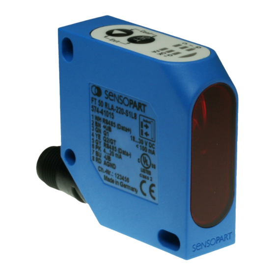
- Page 1 Montage- und Bedienungsanleitung Mounting and operating instructions Instructions de service et de montage FT 50 RLA 70-L8 70-S1L8 220-L8 Abstandssensor 220-S1L8 Distance sensor Capteur de distance...
- Page 2 écrite de SensoPart Industriesensorik GmbH. Nous déclinons toute responsabilité concernent les fautes éventuelles d’impression et autres erreurs qui auraient pu intervenir lors du montage de cette brochure.
- Page 3 Hinweise zur Bedienung: Drücken der Taste nur mit Finger! Keine spitzen Gegenstände verwenden! Instructions for use: Push buttons only with finger! Do not use sharp objects! Indications pour l’utilisation : N’appuyer sur les boutons qu’avec les doigts ! Ne pas utiliser d’objets pointus ! LED ein /LED on / LED allumée LED aus /LED off / LED éteinte LED blinkt /LED flashes / LED clignote...
- Page 4 Maßzeichnung / Dimensional drawing / Plan coté Typ / Type / Ref. X(mm) FT 50 RLA 70 ... 29,4 FT 50 RLA 220 ... 32,5 Abb. 1 / Illustr. 1 / Fig. 1 15300716 Anschluss / Wiring / Raccordement Typ / Type / Ref. Pin 1 Pin 5 dep.
-
Page 5: Table Des Matières
Montage- und Bedienungsanleitung Inhaltsverzeichnis Inhaltsverzeichnis ...............................5 Symbolerklärung ..............................6 Sicherheitshinweise ..............................6 Bestimmungsgemäße Verwendung ........................7 Leistungsmerkmale...............................7 Montage ................................8 5.1 Maßzeichnung .............................8 5.2 Sensormontage ............................8 Elektrische Installation ............................9 Bedienung und Einstellung ..........................10 7.1 Anzeigen und Einstellelemente ........................11 7.2 Funktionen über das Bedienfeld einstellen ....................13 7.2.1 Kurzanleitung (068-13884) siehe Ausklappseite ................13 7.2.2 Mögliche Einstellungen und Betriebsarten ..................13 7.2.3 Modus Differenzmessung .........................20... -
Page 6: Symbolerklärung
Montage- und Bedienungsanleitung Symbolerklärung Warnhinweise und sonstige Hinweise sind in dieser Anleitung durch Symbole gekennzeichnet. Sie werden durch Signalworte eingeleitet. Die verwendeten Symbole sind: WARNUNG ... weist auf eine möglicherweise gefährliche Situation hin, die zum Tod oder zu schweren Verletzungen führen kann, wenn sie nicht gemieden wird. -
Page 7: Bestimmungsgemäße Verwendung
Montage- und Bedienungsanleitung Bestimmungsgemäße Verwendung Der FT 50 RLA ist ein optischer Sensor und misst berührungslos Abstände. Mit zwei FT 50 RLA (nur S1 Typen) können auch Objektdicken oder Dickenunterschiede gemessen werden. WARNUNG Das Produkt ist für das Sichern von Personen nicht zugelassen (kein Sicherheitsbauteil gemäß Maschinenrichtlinie). -
Page 8: Montage
Montage- und Bedienungsanleitung Lichtfleckgeometrie FT 50 RLA 70... FT 50 RLA 220... 1,5 x 3 1,5 x 3,5 1,5 x 3,25 2 x 4,5 29,4 32,5 Abb. 4 15500269 Alle Maße in Millimeter (typische Werte) Montage Maßzeichnung Abb. 5 Abb. 6 15300716 15300065 Sensormontage... -
Page 9: Elektrische Installation
Montage- und Bedienungsanleitung WARNUNG • Nicht in den Strahlengang blicken. Lidschlussreflex nicht unterdrücken. • Bei länger andauerndem Blick in den Strahlengang kann die Netzhaut im Auge beschädigt werden. • Bei der Montage darauf achten, dass der Strahlengang am Ende abgeschlossen ist. •... -
Page 10: Bedienung Und Einstellung
Montage- und Bedienungsanleitung Anschluss Farbe Verwendung Bemerkung 1 (WH) Weiß RS485 Data+ (Y/A) Nur Typ S1 2 (BN) Braun 3 (GN) Grün Als Schaltausgang Q oder Eingang mit optionalen Eingangs- funktionen (siehe Kap. 7. „Bedienung und Einstellung”) 4 (YE) Gelb Als Schaltausgang Q oder Schaltfunktion Good Target oder Good Target... -
Page 11: Anzeigen Und Einstellelemente
Montage- und Bedienungsanleitung Anzeigen und Einstellelemente Die LEDs (Abb. 11) zeigen die gewählten Menüs und Einstellungen an. Farbe Im Betriebsmodus Im Einstellmodus Grün Betriebsanzeige (LED leuchtet, LED blinkt, wenn Einstellmodus wenn Sensor betriebsbereit) (Set Modus) aktiv. Zustandsanzeige: Leuchtet, wenn Funktion aktiviert. Aus, wenn Funktion nicht aktiviert. - Page 12 Montage- und Bedienungsanleitung Die Tasten und ihre Funktion: Mit den Tasten wird der FT 50 RLA konfiguriert. Generelle Bedienfunktionen Tasten Im Betriebsmodus Im Einstellmodus Einstellmodus aktivieren: Einstellmodus verlassen: Gleichzeitiges Drücken (> 3 s) aktiviert den Erst die -Taste und dann zusätzlich die Einstellmodus.
-
Page 13: Funktionen Über Das Bedienfeld Einstellen
Montage- und Bedienungsanleitung HINWEIS Ein Zeitschloss verhindert, dass kurzes, unbeabsichtigtes Drücken der Tasten den Einstellmo- dus aktiviert. Funktionen über das Bedienfeld einstellen 7.2.1 Kurzanleitung (068-13884) siehe Ausklappseite 7.2.2 Mögliche Einstellungen und Betriebsarten Nr. LED Muster Aktion Zustandsanzeige „ZA” Werkseinstellung Beschreibung : Als Schaltausgang oder -eingang setzen EIN, wenn Q als Schaltausgang definiert... - Page 14 Montage- und Bedienungsanleitung Nr. LED Muster Aktion Zustandsanzeige „ZA” Werkseinstellung Beschreibung : Teachen des 2. Schaltpunktes EIN, wenn Messwert gültig AUS, wenn Messwert ungültig oder kein 2. Messwert über- Schaltpunkt nehmen Nach Loslassen der -Taste wird der aktuelle Messwert als 2. Schaltpunkt des Schaltaus- gangs Q gespeichert und mit Schaltpunkt 1 zu einem Schaltfenster verrechnet.
- Page 15 Montage- und Bedienungsanleitung Nr. LED Muster Aktion Zustandsanzeige „ZA” Werkseinstellung Beschreibung Messobjekt Bewegungsrichtung Ansprechzeiten 0,4 ms = 1 Messwert (kein Mittelwert) (Funktion 13) 4 ms = Mittelwertbildung mit 10 Messwerten (Funktion 14) 40 ms = Mittelwertbildung mit 100 Messwerten (Funktion 15) Ansprechzeit Abb.
- Page 16 Montage- und Bedienungsanleitung Nr. LED Muster Aktion Zustandsanzeige „ZA” Werkseinstellung Beschreibung Funktion „Autozero” (mit Q als Steuereingang): EIN, wenn Autozero aktiv Inaktiv AUS, wenn Autozero inaktiv („ZA” = AUS) wechseln Mit dieser Funktion wird die Ausgangskennlinie (4-20 mA) parallel verschoben. Ist die Funktion aktiviert und wird an Q angelegt, wird der aktuelle Messwert mit dem Ausgangswert von 4 mA gleichgesetzt.
- Page 17 Montage- und Bedienungsanleitung Nr. LED Muster Aktion Zustandsanzeige „ZA” Werkseinstellung Beschreibung 20 mA 12 mA 4 mA Autocenter bei 120 mm Abb. 16 300 mm 15500859 Funktion „Maximum (Minimum)-Hold” (mit Q als Steuereingang): EIN, wenn Maximum-Hold aktiv Inaktiv AUS, wenn Maximum-Hold inaktiv („ZA”...
-
Page 18: Beschreibung
Montage- und Bedienungsanleitung Nr. LED Muster Aktion Zustandsanzeige „ZA” Werkseinstellung Beschreibung Funktion „Differenz-Hold” (mit Q als Steuereingang): EIN, wenn Differenz-Hold aktiv Inaktiv AUS, wenn Differenz-Hold inaktiv („ZA” = AUS) wechseln Ist die Funktion aktiviert und wird an Q die Spannung +U angelegt, wird die Differenz von Minimal- und Maximalwert des Messsignals bestimmt und gespeichert. - Page 19 Montage- und Bedienungsanleitung Nr. LED Muster Aktion Zustandsanzeige „ZA” Werkseinstellung Beschreibung Messbereichsanfang Messbereichsende 20 mA mit Messwert-Hold 4 mA 20 mA ohne Messwert-Hold 4 mA Good Target Q Abb. 19 15500275 HINWEIS Funktion 25 bis Funktion 27 nur für FT 50 RLA Ausführung S1. Ein gleichzeitiger Anschluss zu einer SPS-Steuerung oder einem Personal Computer über die RS485-Schnittstelle ist bei der Differenzmessung nicht möglich.
-
Page 20: Modus Differenzmessung
Montage- und Bedienungsanleitung 7.2.3 Modus Differenzmessung HINWEIS Zur Differenzmessung können ausschließlich FT 50 RLA mit demselben Messbereich (Typ FT 50 RLA-70 oder -220 und serieller Schnittstelle Ausführung „S1”) benutzt werden. Ein gleichzeitiger Anschluss zu einer SPS-Steuerung oder einem Personal Computer über die RS485-Schnittstelle ist bei der Differenzmessung nicht möglich. -
Page 21: Anwendungsbeispiele
Montage- und Bedienungsanleitung 1. Beide FT 50 RLA-...S1 Typen so montieren, dass der Abstand zum Objekt immer innerhalb der Tastweite der Sensoren liegt. 2. Sensoren nach Anschlusszeichnung (Abb. 21) verbinden und elektrisch anschließen. 3. Zuerst einen der Sensoren als Slave konfigurieren, dazu Funktion Nr. 26 (Dicken-Differenz) oder Funktion Nr. - Page 22 Montage- und Bedienungsanleitung Parallel-Differenzmessung: Objekterkennung (oder Messung) bei schwankendem Abstand. Oft schwankt der Abstand der Objekte zum Sensor. Hierdurch ist eine sichere Erkennung mit einem Hintergrundtas- ter nicht möglich. Über zwei FT 50 RLA 70/220 und dem Modus Parallel-Differenzmessung (Funktion Nr. 27) kann eine sichere Objekterkennung über den Analogausgang des Masters oder Teachen von Schaltschwellen am Master (Funktion Nr.
-
Page 23: Kommunikation Über Die Serielle Schnittstelle
Zur komfortablen Parametrierung der Sensortypen S1 ist eine Bediensoftware „ProgSensor” ver- fügbar, die im Simulationsmodus auch die für den jeweiligen Fall korrekten Busbefehle anzeigt. Diese kann von unserer Homepage heruntergeladen werden (www.sensopart.de). Beim Anschluss mehrerer Sensoren über den RS485-Bus können sich Reflexionen bilden, wel- che die Übertragung beeinträchtigen. -
Page 24: Telegrammaufbau
Montage- und Bedienungsanleitung Telegrammaufbau Jedes Byte besteht aus einem Selektionsbit (D7) und 7 Daten- bzw. Adressbits (D0 bis D6). Byteaufbau Selektionsbit 7 Datenbits / Adressbits Genereller Telegrammaufbau Ein vollständiges Telegramm, sowohl des Masters als auch des Sensors, besteht aus mindestens 4 Byte und ist wie folgt aufgebaut: Master Antwort Sensor... -
Page 25: Übersicht Der Masterbefehle
Montage- und Bedienungsanleitung 12 Bit Datenwort: Daten 2 Byte i Byte i + 1 Datenwort Bit [14..8] Datenwort Bit [6..0] 12 Bit Datenwort: Daten 3 mit Schaltausgangskennung (Q im Bit D6, Byte i+1) und Good Target (GT im Bit D6 Byte): Byte i Byte i + 1 Datenwort Bit [11..6]... - Page 26 Montage- und Bedienungsanleitung Befehlsbezeichnung Dezimal Hex.: ASCII Bemerkung Beispiel Funktion „Autozero” Die Ausgangskennlinie 4 - 20 mA wird verschoben. 8.5.9 (mit Q als Steuerein- Wird an Q angelegt, wird der aktuelle Messwert gang) mit dem Ausgangswert von 4 mA gleichgesetzt. Die Steigung der Kennlinie bleibt gleich.
-
Page 27: Beispiele Für Masterbefehle
Montage- und Bedienungsanleitung Befehlsbezeichnung Dezimal Hex.: ASCII Bemerkung Beispiel Adresse des Sensors Neue Adresse an Sensor übertragen. 8.5.21 ändern Sensoreinstellung Alle Senoreinstellungen werden gelesen. 8.5.22 lesen Funktion „Messwert Ist die Funktion aktiviert wird, solange kein Objekt 8.5.23 -Hold” im Messbereich ist (OK LED = AUS), der zuletzt gültige Messwert beibehalten und am Anlogausgang ausgegeben. -
Page 28: Schaltausgang Q2 Setzen
Montage- und Bedienungsanleitung 8.5.2 Schaltausgang Q2 setzen Befehl (Byte 3): dezimal 50; hexadezimal 0x32 Parameterformat Parameter: Schaltpunkt 1 12 Bit Datenwort: Daten 1 Konfiguration 7 Bit Datenbyte D0: 0 = Schließer, 1 = Öffner D1: 1 = Impulsverlängerung, 0 = Aus Schaltpunkt 2 12 Bit Datenwort: Daten 1 Antwort (Byte 3):... -
Page 29: Q1 Als Triggereingang Setzen
Montage- und Bedienungsanleitung 8.5.4 als Triggereingang setzen Befehl (Byte 3): dezimal 84; hexadezimal 0x54 Parameter: keine Antwort (Byte 3): dezimal 89; hexadezimal 0x59 Parameter: keine wird als Triggereingang gesetzt. Mit steigender Flanke an Q wird der Messwert bis zum nächsten Triggerereignis festgehalten. -
Page 30: Mittelwertbildung
Montage- und Bedienungsanleitung 8.5.6 Mittelwertbildung Befehl (Byte 3): dezimal 66; hexadezimal 0x42 Parameterformat Parameter: Konfiguration 7 Bit Datenbyte D0 = 1 : 0,4 ms (keine Mittelwertbildung) D1 = 1 : 4 ms (10 Messwerte) D2 = 1 : 40 ms (100 Messwerte) Antwort (Byte 3): dezimal 89;... -
Page 31: Analogausgang Skalieren (20 Ma-Punkt Setzen)
Montage- und Bedienungsanleitung 8.5.8 Analogausgang skalieren (20 mA-Punkt setzen) Befehl (Byte 3): dezimal 72; hexadezimal 0x48 Parameterformat Parameter: Daten 12 Bit Datenwort Daten 1 Antwort (Byte 3): dezimal 89; hexadezimal 0x59 Parameter: keine Der übertragene Messwert wird zum 20 mA Wert des Analogausgangs. Beispieltelegramm (im Beispiel hat der Sensor die Adresse 1) Mastertelegramm... - Page 32 Montage- und Bedienungsanleitung 8.5.10 Funktion „Autocenter” (mit Q als Steuereingang) Befehl (Byte 3): dezimal 67; hexadezimal 0x43 Parameter: keine Antwort (Byte 3): dezimal 89; hexadezimal 0x59 Parameter: keine Mit dieser Funktion wird die Ausgangskennlinie (4-20 mA) verschoben. Ist die Funktion aktiviert und wird an Q angelegt, wird der aktuelle Messwert mit dem Ausgangswert von 12 mA gleichgesetzt.
-
Page 33: Funktion „Differenz-Hold" (Mit Q1 Als Steuereingang)
Montage- und Bedienungsanleitung 8.5.12 Funktion „Minimum-Hold” (mit Q als Steuereingang) Befehl (Byte 3): dezimal 77; hexadezimal 0x4D Parameter: keine Antwort (Byte 3): dezimal 89; hexadezimal 0x59 Parameter: keine Solange an Q anliegt, wird der minimal auftretende Messwert gespeichert. Wenn an Q anliegt, kann der Minimalwert über „Betriebsmesswerte”... -
Page 34: Werkseinstellung Aktivieren
Montage- und Bedienungsanleitung 8.5.14 Werkseinstellung aktivieren Befehl (Byte 3): dezimal 87; hexadezimal 0x57 Parameter: keine Antwort (Byte 3): dezimal 89; hexadezimal 0x59 Parameter: keine Der Sensor wird in Werkseinstellung zurückgesetzt. Beispieltelegramm (im Beispiel hat der Sensor die Adresse 1) Mastertelegramm Antworttelegramm des Sensors Bezeichnung Dezimal... -
Page 35: Einstellungen Dauerhaft Speichern
Montage- und Bedienungsanleitung 8.5.16 Einstellungen dauerhaft speichern Befehl (Byte 3): dezimal 83; hexadezimal 0x53 Parameter: keine Antwort (Byte 3): dezimal 89; hexadezimal 0x59 Parameter: keine Die Einstellungen des Sensors werden im EEPROM gespeichert (so bleiben sie auch nach dem Abschalten der Betriebsspannung erhalten). -
Page 36: Abstandsmesswerte
Montage- und Bedienungsanleitung 8.5.18 Abstandsmesswerte Befehl (Byte 3): dezimal 65; hexadezimal 0x41 Parameter: keine Antwort (Byte 3): dezimal 89; hexadezimal 0x59 Parameterformat Parameter: Daten 12 Bit Datenwort Daten 3 Liest den aktuellen Abstand zum Objekt (Rohdaten) aus. Veränderte Einstellungen der Kennlinie (4 mA-Punkt, 20 mA-Punkt, Min, Max, Autocenter ...) werden nicht berücksichtigt. -
Page 37: Schnelle Messwertausgabe
Montage- und Bedienungsanleitung 8.5.20 Schnelle Messwertausgabe Befehl (Byte 3): dezimal 70; hexadezimal 0x46 Parameter: keine Antwort (Byte 3): dezimal 89; hexadezimal 0x59 Parameter: keine Beispieltelegramm (im Beispiel hat der Sensor die Adresse 1) Mastertelegramm Antworttelegramm des Sensors Bezeichnung Dezimal Hex.: Bezeichnung Dezimal Hex.:... -
Page 38: Sensoreinstellung Lesen
Montage- und Bedienungsanleitung 8.5.22 Sensoreinstellung lesen Befehl (Byte 3): dezimal 63; hexadezimal 0x3F Parameterformat Parameter: keine Antwort (Byte 3): dezimal 89; hexadezimal 0x59 Parameterformat Parameter: Funktion 1 12 Bit Datenwort: Daten 2 D8: Triggereingang D9: Q ist Enable-Eingang D10: X D11: Maximum-Hold D12: Differenz-Hold D13: Q... -
Page 39: Funktion „Messwert-Hold
Montage- und Bedienungsanleitung Mastertelegramm Antworttelegramm des Sensors Bezeichnung Dezimal Hex.: Bezeichnung Dezimal Hex.: 6. Byte Funktion 2 7. Byte 8. Byte Funktion 3 9. Byte 10. Byte Kennlinie 4 mA-Punkt 11. Byte 12. Byte Kennlinie 20 mA-Punkt 13. Byte 14. Byte Schaltschwelle Q 15. -
Page 40: Pflege Und Wartung
Montage- und Bedienungsanleitung Pflege und Wartung Reinigung Bei Verschmutzung die Frontscheibe des Sensors mit einem weichen Tuch und ggf. etwas Kunststoffreiniger reinigen. VORSICHT Niemals aggressive Reinigungsmittel verwenden. Transport, Verpackung, Lagerung Die Lieferung bei Erhalt unverzüglich auf Vollständigkeit und Transportschäden prüfen. Bei Transportschäden den Transporteur benachrichtigen. -
Page 41: Technische Daten
Montage- und Bedienungsanleitung Technische Daten Optische Daten (typ.) FT 50 RLA-70 FT 50 RLA-220 Arbeitsbereich 30 ... 100 mm 80 ... 300 mm Messbereich 70 mm 220 mm Auflösung < 0,1 % vom Arbeitsbereichsendwert (0,1 / 0,3 mm) * Lichtart Gepulstes Laserlicht, rot 650 nm, MTBF >... -
Page 42: Bestellinformationen
Bestellinformationen Artikel-Nr. Typenbezeichnung Beschreibung 574-41018 FT 50 RLA-70-L8 Abstandssensor, 30 ... 100 mm, Aufl. 0,1 % vom Messbereich, 2 x PNP, N.O. / N.C., 4 ... 20 mA, Stecker M12, 8-polig, * 574-41019 FT 50 RLA-70-S1L8 Abstandssensor, 30 ... 100 mm, Aufl. 0,1 % vom Messbereich, 2 x PNP, N.O. - Page 43 Mounting and operating instructions Contents Contents ...................................43 Guide to symbols ..............................44 Safety instructions ..............................44 Correct use .................................45 Performance ...............................45 Mounting ................................46 5.1 Dimensional drawing ..........................46 5.2 Mounting the sensor ..........................46 Electrical installation ............................47 Use and configuration ............................48 7.1 Displays and configuration elements ......................49 7.2 Setting functions with the control panel .....................50 7.2.1 Quick user guide (068-13884) see fold-out page ................50 7.2.2 Possible configurations and operating modes ..................51...
-
Page 44: Guide To Symbols
Mounting and operating instructions Guide to symbols Warnings and other information are signalled by symbols in this manual. They are accompanied by hea- dings. The following symbols are used: WARNING This symbol signals passages in the manual which must be observed at all times. Non-compliance can cause injuries or material damage. -
Page 45: Correct Use
Mounting and operating instructions Correct use The FT 50 RLA is an optical sensor and measures distances without contact. Object thickness or differences in thickness can be measured using two FT 50 RLA (type S1 only). WARNING The product is not approved for the protection of personnel (no safety component according to Machinery Directive). -
Page 46: Mounting
Mounting and operating instructions Dimensions of light spot FT 50 RLA 70... FT 50 RLA 220... 1,5 x 3 1,5 x 3,5 1,5 x 3,25 2 x 4,5 29,4 32,5 Illustr. 4 15500269 All dimensions in mm (typical values) Mounting Dimensional drawing Illustr. -
Page 47: Electrical Installation
Mounting and operating instructions WARNING • Never look into the path of the laser. Do not suppress the reflex to close the eyelids. • Gazing into the beam path for longer periods can damage the retina of the eye. • When mounting the sensor, ensure that the beam path is sealed off at the end. •... -
Page 48: Use And Configuration
Mounting and operating instructions Connection Colour Remark 1 (WH) White RS485 Data+ (Y/A) S1 version only 2 (BN) Brown 3 (GN) Green As signal output Q or input with optional input function (see chapter 7 „Use and configuration”) 4 (YE) Yellow As signal output Q or switching function “good target”... -
Page 49: Displays And Configuration Elements
Mounting and operating instructions Displays and configuration elements The LEDs (illustr. 11) indicate the selected menus and configurations. Colour In operating mode In configuration mode Green Operating indicator (LED lights up, LED flashes, when set-up mode when sensor is ready for use) is active. -
Page 50: Setting Functions With The Control Panel
Mounting and operating instructions General operating functions Keys In operating mode In configuration mode A brief pressing of the key changes the status of respective function or activates storage and confirmation of the set values. No function The function status is indicated by the status indicator ZA (LED ON = active, LED OFF = not active). -
Page 51: Possible Configurations And Operating Modes
Mounting and operating instructions 7.2.2 Possible configurations and operating modes No. LED pattern Status indicator „ZA” Factory setting Description : Set as switching input or output Switch with ON, when Q is defined as switching output = switching output OFF, when Q is defined as input („ZA”... - Page 52 Mounting and operating instructions No. LED pattern Status indicator „ZA” Factory setting Description : Activate pulse stretching by 50 ms for switching outputs Q and Q Switch with ON, when pulse stretching on OFF, when pulse stretching off („ZA” = OFF) = Activate / deactivate Good Target: Switch with ON, when Good Target on (activated)
-
Page 53: Factory Setting
Mounting and operating instructions No. LED pattern Status indicator „ZA” Factory setting Description Measuring object Direction of movement Response times 0.4 ms = measured value (no average) (function 13) 4 ms = averaging with 10 measured values (function 14) 40 ms = averaging with 100 measured values (function 15) Response time Illustr. - Page 54 Mounting and operating instructions No. LED pattern Status indicator „ZA” Factory setting Description „Autom. zero” function (with Q as control input): Switch with ON, if autom. zero active Inactive OFF, if autom. zero inactive („ZA” = OFF) The output characteristics (4-20 mA) are simultaneously displaced with this function. When this function is activated and Q = +U , the current measured value is set as the output value of 4...
- Page 55 Mounting and operating instructions No. LED pattern Status indicator „ZA” Factory setting Description „Autom. centre” function (with Q as control input): Switch with ON, if autom. centre active Inactive OFF, if autom. centre inactive („ZA” = OFF) The output characteristics (4-20 mA) are displaced with this function. When the automatic cen- tre function is activated and Q = +U , the current measured value is equated with the output...
- Page 56 Mounting and operating instructions No. LED pattern Status indicator „ZA” Factory setting Description „Maximum (Minimum)-Hold” (with Q as control input): Switch with ON, if maximum-hold active Inactive OFF, if maximum-hold inactive („ZA” = OFF) If this function is activated and Q = +U , the maximum value of the measuring signal is deter- mined and store.
- Page 57 Mounting and operating instructions No. LED pattern Status indicator „ZA” Factory setting Description Locking keys: Switch with ON, if locking keys active Inactive OFF, if locking keys inactive („ZA” = OFF) If function is activated locking becomes active once the setting mode has been quit. It is possi- ble to unlock keys with the functions „factory setting”...
-
Page 58: Differential Measurement Mode
Mounting and operating instructions No. LED pattern Status indicator „ZA” Factory setting Description Switch differential thickness measurement mode (slave) on / off: Switch with ON, differential thickness measurement mode Inactive slave active („ZA” = OFF) OFF, differential thickness measurement mode slave inactive ... - Page 59 Mounting and operating instructions Master Slave RS485 Data+ (Y/A) RS485 Data- (Z/B) Illustr. 21 15400172 The following steps must be carried out for differential measurement: INFORMATION We recommend resetting sensors to factory setting (function 22, or 7.2.2) before configuration of sensors as master or slave.
-
Page 60: Examples Of Use
Mounting and operating instructions Examples of use Differential thickness measurement with wide wooden boards Two opposite facing sensors enable non-contact measurement and control of the thickness of the wood or wooden boards. A change in thickness is indicated at the analogue output of the master. 12 mA corresponds with the taught reference thickness of the object. -
Page 61: Communication Via The Serial Interface
INFORMATION For a convenient parameterisation of the S1 sensor types there is an operating software „Pro- gSensor” available for download on our website (www.sensopart.de). In simulation mode, it indicates the relevant correct bus commands. If several sensors are connected via the RS485 bus, reflections can occur which may impair transmission. -
Page 62: Basic Characteristics And Parameters Of The Serial Sensor Interface
Mounting and operating instructions Basic characteristics and parameters of the serial sensor interface The serial interface of the sensor has the following characteristics: Fixed factory configuration modifiable Hardware RS485, half-duplex Pin1 Data+ (Y/A), Pin5 Data- (Z/B) Data transfer rate 38400 Baud Stop bits Parity Bits / Byte... - Page 63 Mounting and operating instructions Possible reply telegram from sensor Decimal Hex.: ASCII Meaning Command has been carried out Command could not be carried out; Possible causes: check sum or parameter / command incorrect 12 bit and 7 bit data is transferred in the parameter bytes (4th byte to (n-1) byte). The following formats are used: Possible parameter format: 7 bit data byte Data byte bit [6..0]...
-
Page 64: Overview Of Master Commands
Mounting and operating instructions Overview of master commands: Command description Dec. Hex.: ASCII Remark Example Set switching output Q Switching output Q is set: 8.5.1 1st and 2nd switch point N.C / N.O. Pulse stretching Set switching output Q Switching output Q is set: 8.5.2 1st and 2nd switch point... -
Page 65: Examples For Master Commands
Mounting and operating instructions Command description Dec. Hex.: ASCII Remark Example Lock and unlock keys This command locks or unlocks the control panel 8.5.15 keys. Store settings perma- The set parameters and data are stored permanently 8.5.16 nently in the sensor. They thus remain in the sensor even after power supply has been disconnected. -
Page 66: Set Switching Output Q1
Mounting and operating instructions 8.5.1 Set switching output Q Command (Byte 3): decimal 49; hexadecimal 0x31 Parameter format: Parameter: Switching point 1 12 bit data item: data 1 Configuration 7 bit data byte D0: 0 = N.O., 1 = N.C. D1: 1 = pulse stretching, 0 = OFF Switching point 2 12 bit data item: data 1... -
Page 67: Set Q2 As Output „Good Target
Mounting and operating instructions Example telegram (in this example the sensor has the address 1, signal output Q is defined as N.O without pulse stretching, switch point 1 = selected value, switch point 2 = 0) Master telegram Sensor’s reply telegram Designation Decimal Hex.:... -
Page 68: Set Q1 As Control Input For Laser On / Off
Mounting and operating instructions Example telegram (in the example, the sensor has the address 1) Master telegram Sensor’s reply telegram Designation Decimal Hex.: Designation Decimal Hex.: 1. Byte Address 1. Byte Address 2. Byte Length 2. Byte Length 3. Byte Command 3. -
Page 69: Scaling Analogue Output (Set 4 Ma Point)
Mounting and operating instructions Example telegram (in the example, the sensor has the address 1. Averaging is set to 4 ms.) Master telegram Sensor’s reply telegram Designation Decimal Hex.: Designation Decimal Hex.: 1. Byte 1. Byte Address Address 2. Byte Length 2. -
Page 70: Autom. Zero" Function (With Q1 As Control Input)
Mounting and operating instructions Example telegram (in the example, the sensor has the address 1) Master telegram Sensor’s reply telegram Designation Decimal Hex.: Designation Decimal Hex.: 1. Byte Address 1. Byte Address 2. Byte Length 2. Byte Length 3. Byte Command 3. -
Page 71: Maximum-Hold" Function (With Q1 As Control Input)
Mounting and operating instructions Example telegram (in the example, the sensor has the address 1) Master telegram Sensor’s reply telegram Designation Decimal Hex.: Designation Decimal Hex.: 1. Byte 1. Byte Address Address 2. Byte Length 2. Byte Length 3. Byte Command 3. -
Page 72: Difference Hold" Function (With Q1 As Control Input)
Mounting and operating instructions 8.5.13 „Difference Hold” function (with Q as control input) Command (Byte 3): decimal 68; hexadecimal 0x44 Parameter: Reply (Byte 3): decimal 89; hexadecimal 0x59 Parameter: Provided Q = +U , the difference between the measured values is saved. When Q , the determined value is transmitted at the analogue output. -
Page 73: Permanent Storage Of Configurations
Mounting and operating instructions Example telegram (in the example, the sensor has the address 1, the key lock is active) Master telegram Sensor’s reply telegram Designation Decimal Hex.: Designation Decimal Hex.: 1. Byte 1. Byte Address Address 2. Byte Length 2. -
Page 74: Distance Measured Values
Mounting and operating instructions Example telegram (in the example, the sensor has the address 1, Q is set to high) Master telegram Sensor’s reply telegram Designation Decimal Hex.: Designation Decimal Hex.: 1. Byte Address 1. Byte Address 2. Byte Length 2. -
Page 75: Fast Measured Value Output
Mounting and operating instructions Example telegram (in the example, the sensor has the address 1) Master telegram Sensor’s reply telegram Designation Decimal Hex.: Designation Decimal Hex.: 1. Byte 1. Byte Address Address 2. Byte Length 2. Byte Length 3. Byte Command 3. -
Page 76: Read Sensor Settings
Mounting and operating instructions Example telegram (in the example, the sensor has the address 1, it is switched to 2) Master telegram Sensor’s reply telegram Designation Decimal Hex.: Designation Decimal Hex.: 1. Byte Address 1. Byte Address 2. Byte Length 2. -
Page 77: Meas. Value Hold" Function
Mounting and operating instructions Example telegram (in the example, the sensor has the address 1) Master telegram Sensor’s reply telegram Designation Decimal Hex.: Designation Decimal Hex.: 1. Byte 1. Byte Address Address 2. Byte Length 2. Byte Length 3. Byte Command 3. -
Page 78: Care And Maintenance
Mounting and operating instructions Example telegram (in the example, the sensor has the address 1, „meas. value hold” is activated) Master telegram Sensor’s reply telegram Designation Decimal Hex.: Designation Decimal Hex.: 1. Byte Address 1. Byte Address 2. Byte Length 2. -
Page 79: Technical Data
Mounting and operating instructions Description of error Possible cause Remedy Master - slave mode does not One sensor is not in correct mode. Reprogram the sensor whose LED is not function. alight. LED C is only alight on one One sensor does not have function Use the sensor that does not have function sensor. -
Page 80: Order Information
Order information Part no. Part name Description 574-41018 FT 50 RLA-70-L8 Distance sensor, 30 ... 100 mm, resolution 0.1 % of measuring range, 2 x PNP, N.O. / N.C., 4 ... 20 mA, M12 8-pin connector, * 574-41019 FT 50 RLA-70-S1L8 Distance sensor, 30 ... - Page 81 If your PC has a USB interface, the additionalCUSB-RS485-Set * is required.. see accessory list for part numbers INFORMATION Data sheets, instruction manuals and operating software (Progsensor) are available for downloa- ding on www.sensopart.de. FT 50 RLA Disctance sensor - GB - 068-13671 - 20.04.2009-05...
- Page 82 Instructions de service et de montage Table des matières Table des matières ..............................82 Explication des symboles ...........................83 Instructions de sécurité ............................83 Utilisation conforme à la destination de l’appareil ....................84 Caractéristiques de fonctionnement ........................84 Montage ................................85 5.1 Plan coté ..............................85 5.2 Montage du capteur ...........................85 Installation électrique ............................86 Commande et réglage ............................87 7.1 Témoins de fonctionnement et éléments de réglage .................88...
-
Page 83: Explication Des Symboles
Instructions de service et de montage Explication des symboles Les avertissements et autres messages contenus dans ce manuel sont repérés par des symboles. Ils sont également précédés de mots les signalant. Les symboles utilisés sont les suivants : AVERTISSEMENT ... indique une situation potentiellement dangereuse pouvant provoquer la mort ou des blessures graves si elle n'est pas évitée. -
Page 84: Utilisation Conforme À La Destination De L'appareil
Instructions de service et de montage Utilisation conforme à la destination de l’appareil Le FT 50 RLA est un capteur optique sans contact qui mesure les distances. Il est possible de mesurer l’épaisseur d’objets ou la différence d’épaisseur en utilisant deux FT 50 RLA (uniquement les types S1). AVERTISSEMENT Le produit n'est pas compatible avec la sécurité... -
Page 85: Montage
Instructions de service et de montage Géométrie du spot FT 50 RLA 70... FT 50 RLA 220... 1,5 x 3 1,5 x 3,5 1,5 x 3,25 2 x 4,5 29,4 32,5 Fig. 4 15500269 Toutes les dimensions en mm (valeurs types) Montage Plan coté... -
Page 86: Installation Électrique
Instructions de service et de montage AVERTISSEMENT • Ne pas regarder dans la trajectoire du rayon laser. Ne pas empêcher le réflexe de fermeture des paupières. • Risques de lésions sur la cornée quand on regarde dans la trajectoire du rayon laser de façon continue. -
Page 87: Commande Et Réglage
Instructions de service et de montage Raccordement Couleur Utilisation Remarque 1 (WH) Blanc RS485 Data+ (Y/A) Uniquement Type S1 2 (BN) Brun 3 (GN) Vert En tant que sortie de commutation Q ou entrée avec fonctions d'entrées en option (voir chap. 7 „ Commande et réglage ”) 4 (YE) Jaune En sortie de commutation Q... -
Page 88: Témoins De Fonctionnement Et Éléments De Réglage
Instructions de service et de montage Témoins de fonctionnement et éléments de réglage Les LED (fig. 11) indiquent les menus et réglages sélectionnés. Couleur En mode de travail En mode de réglage Vert Affichage de fonctionnement LED clignote quand le mode de (LED est allumée quand le cap- réglage (mode Set) est activé. -
Page 89: Régler Fonctions De L'interface Des Commandes
Instructions de service et de montage Fonctions générales de commande Touches En mode de travail En mode de réglage Appuyer brièvement sur -Cela change l’état de la fonction considérée ou conduit à la sauve- Sans fonction garde et à la confirmation de valeurs réglées. L’état de la fonction est affiché... -
Page 90: Réglages Et Modes De Fonctionnement Possibles
Instructions de service et de montage 7.2.2 Réglages et modes de fonctionnement possibles N° Échantillon Témoin d'état „ ZA ” Réglage usine Désignation : Régler comme sortie ou entrée de commutation Changer avec ON, quand Q est défini comme sortie de = Sortie de commutation commutation („... - Page 91 Instructions de service et de montage N° Échantillon Témoin d'état „ ZA ” Réglage usine Désignation : Régler fonction de commutation (N.O. ou N.C.) Changer avec ON, quand N.C. (contact d’ouverture) N.O. / Contact fermeture OFF, quand N.O. (contant de fermeture) („...
- Page 92 Instructions de service et de montage N° Échantillon Témoin d'état „ ZA ” Réglage usine Désignation Couper la recherche de la moyenne : Activer avec ON = moyenne OFF Moyenne off („ ZA ” = ON) Explication sur la recherche de la moyenne : Grâce à...
- Page 93 Instructions de service et de montage N° Échantillon Témoin d'état „ ZA ” Réglage usine Désignation Graduer la sortie analogique (mettre des points en 4 mA) : Garder la valeur ON, quand objet en champ 20 mA = Début du champ de mesurée avec OFF, quand objet en dehors du champ mesure...
- Page 94 Instructions de service et de montage N° Échantillon Témoin d'état „ ZA ” Réglage usine Désignation Fonction „ Autozero ” (avec Q en entrée de commande) : Changer avec ON, quand Autozero aktivé Inactif OFF, quand Autozero inactif („ ZA ” = OFF) Avec cette fonction, la ligne de reconnaissance de sortie (4 mA) est poussée de manière parallèle.
- Page 95 Instructions de service et de montage N° Échantillon Témoin d'état „ ZA ” Réglage usine Désignation Fonction „ Autocenter ” (avec Q en entrée de commande) : Changer avec ON, quand Autocenter activé Inactif OFF, quand Autocenter inactif („ ZA ” = OFF) Avec cette fonction, la ligne de reconnaissance de sortie (4 mA) est poussée de manière paral- lèle.
- Page 96 Instructions de service et de montage N° Échantillon Témoin d'état „ ZA ” Réglage usine Désignation Fonction „ Hold maximum (minimum) ” (avec Q en entrée de commande) : Changer avec ON, quand Hold maxi est activé Inactif OFF, quand Hold max inactif („...
- Page 97 Instructions de service et de montage N° Échantillon Témoin d'état „ ZA ” Réglage usine Désignation Activer les réglages usine : Activer avec ZA est allumée aussi longtemps que la touche est enfoncée. Si on appuie sur la touche , tous les réglages usine sont réactivés. Cette étape ne peut pas être annulée.
-
Page 98: Mode Mesure D'une Différence
Instructions de service et de montage N° Échantillon Témoin d'état „ ZA ” Réglage usine Désignation REMARQUE Les fonctions 25 à 27 ne sont disponibles que sur le FT 50 RLA version S1. Le raccordement simultané à un système de commande SPS ou à un PC par l’interface RS485 n’est pas possible lors de la mesure de différence. - Page 99 Instructions de service et de montage Maître Esclave RS485 Data+ (Y/A) RS485 Data- (Z/B) Fig. 21 15400172 Les étapes suivantes sont à exécuter pour la mesure de différence : REMARQUE Nous conseillons, avant de configurer les capteurs en Maître et Esclave, de les remettre au régla- ge usine (fonction n°...
-
Page 100: Applications Type
Instructions de service et de montage Applications type Mesure de différence d’épaisseur sur de larges planches de bois Avec 2 capteurs placés l’un en face de l’autre, on mesure et on contrôle sans contact l’épaisseur de bois ou de planches de bois. Tout changement dans l’épaisseur est indiqué sur la sortie analogique du Maître. La largeur de référence de l’objet correspond à... -
Page 101: Communication Via L'interface Série
Pour un paramétrage simple des capteurs de type S1, il y a la possibilité de télécharger de notre site internet (www.sensopart.fr) un logiciel d'utilisation „ ProgSensor ”. Ce logiciel indique, en mode simulation, la commande bus correcte pour chaque cas. -
Page 102: Propriétés Et Paramètres De Base De L'interface Série Du Capteur
Instructions de service et de montage Propriétés et paramètres de base de l'interface série du capteur L’interface série du capteur a les caractéristiques suivantes : configuration usine fixe modifiable Matériel RS485, semi-duplex Pin1 Data+ (Y/A), Pin 5 Data- (Z/B) Taux de transmission des données 38400 Baud Bits de stop Parité... - Page 103 Instructions de service et de montage Possibilité de télégramme de réponse du capteur Décimal Hex.: ASCII Signification La commande a été exécutée La commande n'a pas pu être exécutée ; causes possibles : somme de contrôle ou paramètre / commande incorrects Les octets de paramètres (4e octet à...
-
Page 104: Aperçu Des Commandes Maître
Instructions de service et de montage Aperçu des commandes Maître Désignation de la Décimal Hex.: ASCII Remarque Exemple commande Régler sortie de Sortie de commutation Q est fixée : 8.5.1 commutation Q 1. et 2. point de commutation Ouverture / Fermeture Maintien à... - Page 105 Instructions de service et de montage Désignation de la Décimal Hex.: ASCII Remarque Exemple commande Fonction Tant que Q est joint à +U , la différence des va- 8.5.13 „ Hold différence ” leurs mesurées apparues est gardée en mémoire. (avec Q en entrée de Si Q...
-
Page 106: Exemples De Commandes Maître
Instructions de service et de montage Exemples de commandes Maître REMARQUE La pluplart des protocoles de commande sont représentés dans le logiciel ProgSensor (Partie Simulati- on du capteur). 8.5.1 Régler sortie de commutation Q Commande (octet 3): décimal 49; hexadécimal 0x31 Format de paramètre Paramètres: Point de commutation 1... -
Page 107: Régler Q2 Sortie De Commutation En „ Good Target
Instructions de service et de montage Réponse (octet 3): décimal 89; hexadécimal 0x59 Paramètres: La sortie de commutation Q2 est définie (points de commutation 1+2, configuration). Exemple de télégramme (dans l’exemple, le capteur a l’adresse 1, la sortie de commutation Q est définie comme fermeture sans maintien à... -
Page 108: Régler Q1 Comme Entrée Trigger
Instructions de service et de montage 8.5.4 Régler Q comme entrée Trigger Commande (octet 3): décimal 84; hexadécimal 0x54 Paramètres: Réponse (octet 3): décimal 89; hexadécimal 0x59 Paramètres: est utilisé en entrée Trigger. Avec flancs montants sur Q , la valeur mesurée est maintenue jusqu’au prochain événement Trigger. -
Page 109: Graduer La Sortie Analogique (Régler Point 4 Ma)
Instructions de service et de montage Réponse (octet 3): décimal 89; hexadécimal 0x59 Paramètres: Le résultat de valeur (signal de sortie) est lissé par la recherche de la moyenne. Pour cela, les valeurs mesurées sont lues les unes après les autres dans une mémoire et la moyenne arithmétique est formée. Le nombre des valeurs mesurées qui servent à... -
Page 110: Fonction „ Autozero " (Avec Q1 En Entrée De Commande)
Instructions de service et de montage Exemple de télégramme (dans l’exemple, le capteur a l’adresse 1) Télégramme du Maître Télégramme de réponse du capteur Désignation Décimal Hex.: Désignation Décimal Hex.: 1. Byte Adresse 1. Byte Adresse 2. Byte Longueur 2. Byte Longueur 3. - Page 111 Instructions de service et de montage Exemple de télégramme (dans l’exemple, le capteur a l’adresse 1) Télégramme du Maître Télégramme de réponse du capteur Désignation Décimal Hex.: Désignation Décimal Hex.: 1. Byte Adresse 1. Byte Adresse 2. Byte Longueur 2. Byte Longueur 3.
-
Page 112: Fonction „ Hold Différence " (Avec Q1 En Entrée De Commande)
Instructions de service et de montage 8.5.13 Fonction „ Hold différence ” (avec Q1 en entrée de commande) Commande (octet 3): décimal 68; hexadécimal 0x44 Paramètres: Réponse (octet 3): décimal 89; hexadécimal 0x59 Paramètres: Tant que Q est joint à +U , la différence des valeurs mesurées mesurées est gardée en mémoire. -
Page 113: Sauvegarde Définitive Des Réglages
Instructions de service et de montage Exemple de télégramme (dans l’exemple, le capteur a l’adresse 1, le verrouillage des touches est activé) Télégramme du Maître Télégramme de réponse du capteur Désignation Décimal Hex.: Désignation Décimal Hex.: 1. Byte Adresse 1. Byte Adresse 2. -
Page 114: Valeurs De Mesure De Distance
Instructions de service et de montage Exemple de télégramme (dans l’exemple, le capteur a l’adresse 1, Q est réglé sur high) Télégramme du Maître Télégramme de réponse du capteur Désignation Décimal Hex.: Désignation Décimal Hex.: 1. Byte Adresse 1. Byte Adresse 2. -
Page 115: Transmission Rapide Des Valeurs Mesurées
Instructions de service et de montage Exemple de télégramme (dans l’exemple, le capteur a l’adresse 1) Télégramme du Maître Télégramme de réponse du capteur Désignation Décimal Hex.: Désignation Décimal Hex.: 1. Byte Adresse 1. Byte Adresse 2. Byte Longueur 2. Byte Longueur 3. -
Page 116: Désignation
Instructions de service et de montage Exemple de télégramme (dans l’exemple, le capteur a l’adresse 1, celle-ci est modifée en 2) Télégramme du Maître Télégramme de réponse du capteur Désignation Décimal Hex.: Désignation Décimal Hex.: 1. Byte Adresse 1. Byte Adresse 2. -
Page 117: Fonction „ Hold Valeur Mesurée
Instructions de service et de montage Exemple de télégramme (dans l’exemple, le capteur a l’adresse 1) Télégramme du Maître Télégramme de réponse du capteur Désignation Décimal Hex.: Désignation Décimal Hex.: 1. Byte Adresse 1. Byte Adresse 2. Byte Longueur 2. Byte Longueur 3. -
Page 118: Entretien Et Maintenance
Instructions de service et de montage Exemple de télégramme (dans l’exemple, le capteur a l’adresse 1, Hold valeur mesurée est activée) Télégramme du Maître Télégramme de réponse du capteur Désignation Décimal Hex.: Désignation Décimal Hex.: 1. Byte Adresse 1. Byte Adresse 2. -
Page 119: Caractéristiques Techniques
Instructions de service et de montage Description du défaut Cause possible Remède Le mode Maître-Esclave ne Un des capteurs n’est pas dans le Reprogrammer le capteur dont la LED ne fonctionne pas. bon mode. s’allume pas. La LED C n’est allumée que sur Un des capteurs ne dispose pas de Utiliser le capteur qui ne dispose pas de la 1 capteur. -
Page 120: Référence De Commande
Référence de commande N° Article Référence Désignation 574-41018 FT 50 RLA-70-L8 Capteur de distance, 30 ... 100 mm, résolution 0,1 % du champ de mesure, 2 x PNP, N.O. / N.C., 4 ... 20 mA, connecteur M12, 8 pôles, * 574-41019 FT 50 RLA-70-S1L8 Capteur de distance, 30 ... - Page 121 Pour la référence, voir la liste des accessoires REMARQUE Les fiches techniques, les instructions de service et le logiciel de commande (Progsensor) sont disponibles pour le téléchargement à l'adresse www.sensopart.de. FT 50 RLA Capteur de distance - F - 068-13671 - 20.04.2009-05...
- Page 122 Kontaktadressen / Contact addresses / Contacts Deutschland France SensoPart Industriesensorik GmbH SensoPart France SARL Am Wiedenbach 1 11, rue Albert Einstein D-79695 Wieden Espace Mercure Tel.: +49 (0) 7665 - 94769 - 0 F-77420 Champs - Marne la Vallée Fax: +49 (0) 7665 - 94769 - 765 Tél.: +33 (0) 1 64 73 00 61...