Publicité
Les langues disponibles
Les langues disponibles
Liens rapides
Publicité
Chapitres

Manuels Connexes pour oventrop Unibox ERTL


Sommaire des Matières pour oventrop Unibox ERTL
- Page 1 Premium Armaturen + Systeme Rücklauftemperaturregelung „Unibox E RTL“ Betriebsanleitung Return flow temperature control "Unibox ERTL" Operating instructions Régulation de la température de retour « Unibox ERTL » Notice d'utilisation...
-
Page 3: Table Des Matières
Unibox E RTL Inhaltsverzeichnis Inhalt Seite Allgemeine Angaben ..................5 Gültigkeit der Anleitung ..................... 5 Lieferumfang ........................5 Kontakt ..........................5 Urheber- und Schutzrechte ....................5 Konformitätserklärung ....................... 5 Verwendete Symbole ......................5 Sicherheitsbezogene Informationen ..............6 Normative Vorgaben ......................6 Bestimmungsgemäße Verwendung .................. 6 Änderungen am Produkt .................... - Page 4 Inhaltsverzeichnis Unibox E RTL Betrieb ......................12 Störungen beheben ..................13 Instandhaltung ....................14 Entsorgung .....................14 Anhang ......................15 12.1 Häufige Fragen ........................ 15 Abbildungsverzeichnis ..................18 Index ........................19 Glossar ......................20 102273180-V02.06.2019...
-
Page 5: Allgemeine Angaben
Der Lieferumfang umfasst: beschäftigten Personen bestimmt. • „Unibox E RTL“ mit Bauschutzabdeckung 1.5 Konformitätserklärung • Abdeckplatte Hiermit erklärt die Oventrop GmbH & Co. KG, • Winkel dass dieses Produkt in Übereinstimmung mit • Betriebsanleitung den grundlegenden Anforderungen und den einschlägigen Bestimmungen der betreffenden EU-Richtlinien hergestellt wurde. -
Page 6: Sicherheitsbezogene Informationen
Sicherheitsbezogene Informationen Unibox E RTL Sicherheitsbezogene 2.4 Warnhinweise Informationen Jeder Warnhinweis enthält folgende Elemente: 2.1 Normative Vorgaben Warnsymbol SIGNALWORT Beachten Sie die am Installationsort geltenden Art und Quelle der Gefahr! rechtlichen Rahmenbedingungen. Mögliche Folgen, wenn die Gefahr ein- Es gelten die aktuell gültigen Normen, Regeln tritt bzw. -
Page 7: Verletzungsgefahr Bei Unsachgemäßer Arbeit
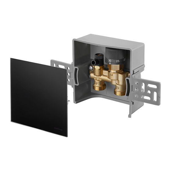
Unibox E RTL Technische Beschreibung Technische Beschreibung 2.5.2 Verletzungsgefahr bei unsachgemäßer Arbeit 3.1 Aufbau Kantige Bauteile, Spitzen und Ecken am und im Produkt können Verletzungen verursachen. f Sorgen Sie vor Beginn der Arbeiten für ausreichenden Platz. f Gehen Sie mit offenen oder scharfkantigen Bauteilen vorsichtig um. -
Page 8: Funktionsbeschreibung
Technische Beschreibung Unibox E RTL 3.3 Funktionsbeschreibung Die „Unibox E RTL“ dient zur Begrenzung der Rücklauftemperatur einer Flächentemperie- rung. Die Einbauposition der „Unibox E RTL“ ist so zu wählen, dass zunächst der Heizkreis und anschließend das Ventil der „Unibox E RTL“ durchströmt wird. -
Page 9: Technische Daten
Unibox E RTL Zubehör und Ersatzteile 3.5 Technische Daten Transport und Lagerung Transportieren Sie das Produkt in der Original- Betriebstemperatur t s max. 100°C verpackung. Betriebsdruck p s max. 10 bar Lagern Sie das Produkt unter folgenden Bedin- Differenzdruck max. 1 bar gungen: Bautiefe 57 mm... -
Page 10: Montage „Unibox E Rtl
Montage Unibox E RTL 6.2 Montage „Unibox E RTL“ ACHTUNG Sachschaden durch Schmier- Die „Unibox E RTL“ muss sich mittel! immer am Ende des Flächentempe- rierungskreises befinden (siehe 3.3 Dichtungen können durch die Verwen- auf Seite 8). dung von Fetten oder Ölen zerstört werden. -
Page 11: Inbetriebnahme
Unibox E RTL Inbetriebnahme 4. Nutzen Sie die beiliegenden Winkel (siehe 1.2 auf Seite 5) um die „Unibox E RTL“ im Formschacht auszurichten und zu befestigen. Abb. 8: Bauabdeckung aufsetzen 7.2 Vorarbeiten Funktionsheizen Führen Sie das Funktionsheizen durch um die ordnungsgemäße Funktion der Flächentempe- Abb. -
Page 12: Funktionsheizen
Betrieb Unibox E RTL 7.3 Funktionsheizen Gehen Sie beim Funktionsheizen wie folgt vor: 1. Öffnen Sie das Ventil vollständig durch betätigung des Handrads (siehe 3.4 auf Seite 8). Regeln Sie die Vorlauftempera- tur nun über die Steuerung des Wärme erzeugers. 2. -
Page 13: Störungen Beheben
Unibox E RTL Störungen beheben Störungen beheben STÖRUNG URSACHE BEHEBUNG Die Flächentemperierung wird Die „Unibox E RTL“ ist im Die „Unibox E RTL“ muss nicht warm. Vorlauf eingebaut. von einer Rücklauftempe- raturbegrenzung in eine Einzelraumtemperaturregelung („Unibox T“) umgebaut wer- den. Verwenden Sie dafür den Umrüstsatz „Unibox T“. -
Page 14: Instandhaltung
Instandhaltung Unibox E RTL 10. Instandhaltung Prüfen Sie die Dichtheit und Funktion der Ar- matur und ihrer Verbindungsstellen im Rahmen der Anlagenwartung regelmäßig. 11. Entsorgung ACHTUNG Verschmutzungsgefahr für die Umwelt! Nicht fachgerechte Entsorgung (z. B. im Hausmüll) kann zu Umweltschäden führen. -
Page 15: Anhang
Unibox E RTL Anhang 12. Anhang 12.1 Häufige Fragen FRAGE ANTWORT Können zwei Heizkreise an Ja, mit einem „Duo-Anschlussstück“ können zwei gleich große eine „Unibox E RTL“ ange- Heizkreise an eine „Unibox E RTL“ angeschlossen werden. schlossen werden? Jeder Flächentemperierungskreis kann bis zu 80 m Rohrlänge betragen, wenn man 16er/17er Rohr verwendet. -
Page 16: Abb. 12: Anschluss Mit Bypass-Ventil Und Heizkörperverschraubung Mit Bypass
Anhang Unibox E RTL FRAGE ANTWORT Kann ich die „Unibox E RTL“ Die „Unibox E RTL“ ist für Einrohrheizungsanlagen geeignet. auch bei einer Einrohrheizung Möglichkeit 1: verwenden? Abb. 12: Anschluss mit Bypass-Ventil und Heizkörperver- schraubung mit Bypass Bypass-Ventil Heizkörperverschraubung mit Bypass - Der Volumenstrom und Druckverlust können sich erhöhen. -
Page 17: Abb. 14: Anschluss Mit „Unibox Rla
Unibox E RTL Anhang FRAGE ANTWORT - Der Volumenstrom und Druckverlust können sich erhöhen. - Beachten Sie die Druckverlust und Geräuschkennlinie der Heizkörperarmaturen. - Regulieren Sie das Bypass-Ventil so ein, dass genug Wasser durch die Flächentemperierung fließt. - Bei geschlossenem Ventil dürfen am Heizkörper keine Ge- räusche entstehen. -
Page 18: Abbildungsverzeichnis
Abb. 8: Bauabdeckung aufsetzen ....................11 Abb. 9: Abdeckplatte aufsetzen ....................12 Abb. 10: „Unibox ERTL“ im Vorlauf eingebaut ................13 Abb. 11: Anschlussschema zwei Heizkreise mit „Duo-Anschlussstück“ ........15 Abb. 12: Anschluss mit Bypass-Ventil und Heizkörperverschraubung mit Bypass ....... 16 Abb. -
Page 19: Index
Unibox E RTL Index 14. Index Seite Bypass-Ventil .......................... 16, 17 Duo-Anschlussstück ........................15 Einrohrheizung ..........................16 Einzelraumtemperaturregelung ..................... 13 Kontakt ............................5 Lieferumfang ........................... 5 Sanitär-, Heizungs- und Klimatechnik-Fachhandwerker ..............6 Schmiermittel ..........................10 Technische Daten ..........................9 Zubehör ............................9 102273180-V02.06.2019... -
Page 20: Glossar
Glossar Unibox E RTL 15. Glossar Bypass-Ventil Ein Bypass-Ventil ist ein Absperr- oder Drosselventil, das eingesetzt wird um ein anderes Bauteil zu umgehen. Das Bypassventil ist in einer Leitung verbaut, welche das andere Bauteil umgeht. Mit dem Einbau dieses Ventils werden verschiedene Ziele verfolgt: •... - Page 23 Unibox E RTL Contents Contents Page General information ..................25 Validity of the operating instructions ................25 Extent of supply ......................25 Contact ..........................25 Copyright and protective rights ..................25 Declaration of conformity ....................25 Symbols used ........................25 Safety-related information ................26 Normative directives ......................
- Page 24 Contents Unibox E RTL Operation ......................32 Troubleshooting .....................33 Maintenance ....................34 Disposal ......................34 Appendix ......................35 12.1 FAQs ..........................35 Illustration index .....................38 Index ........................39 Glossary ......................40 102273180-V02.06.2019...
-
Page 25: General Information
• "Unibox E RTL" with construction site 1.5 Declaration of conformity protection cover Oventrop GmbH & Co. KG hereby declares that • Cover plate this product complies with the basic require- • Bracket ments and other relevant provisions of the •... -
Page 26: Safety-Related Information
Safety-related information Unibox E RTL Safety-related information 2.4 Warnings Each warning contains the following elements: 2.1 Normative directives Observe the legal requirements applicable at Warning symbol SIGNAL WORD the installation location. Type and source of danger! The current standards, regulations and guide- Possible consequences if the danger lines apply. -
Page 27: Risk Of Injury In Case Of Improper Work
Unibox E RTL Technical description Technical description 2.5.2 Risk of injury in case of improper work 3.1 Construction Angular components, protrusions and edges both inside and outside the product may cause injuries. f Before starting work, make sure that there is sufficient space. -
Page 28: Functional Description
Technical description Unibox E RTL 3.3 Functional description "Unibox E RTL" is intended to restrict the return flow temperature for surface tempera- ture balance. Choose the installation position of "Unibox E RTL" so that medium initially flows through the heating circuit before it flows through the "Unibox E RTL"... -
Page 29: Technical Data
Unibox E RTL Accessories and spare parts 3.5 Technical data Transport and storage Transport the product in its original packaging. Operating temperature ts max. 100 °C The product must be stored under the following Operating pressure ps max. 10 bar conditions: Differential pressure max. -
Page 30: Unibox E Rtl" Installation
Installation Unibox E RTL 6.2 "Unibox E RTL" installation NOTICE Risk of damage due to lubri- "Unibox E RTL" must always be cants! located at the end of the surface temperature balance circuit (see 3.3 Seals may be destroyed by greasing on page 28). -
Page 31: Commissioning
Unibox E RTL Commissioning 4. Use the enclosed brackets (see 1.2 on page 25) to align and secure "Unibox E RTL" in the forming shaft. Illustr. 8: Positioning the protection cover 7.2 Preliminary work for incremental heating test Illustr. 7: "Unibox E RTL" with brackets Carry out an incremental heating test to check the correct function of the surface temperature 5. -
Page 32: Incremental Heating Test
Operation Unibox E RTL 7.3 Incremental heating test Proceed as follows during the incremental heating test: 1. Fully open the valve and operate the hand- wheel (see 3.4 on page 28). Control the flow temperature using the heat generator control. 2. -
Page 33: Troubleshooting
Unibox E RTL Troubleshooting Troubleshooting MALFUNCTION CAUSE REMEDY Surface temperature balance "Unibox E RTL" has been Convert "Unibox E RTL" from does not reach hot tempera- installed in the supply. a return flow temperature tures. limiter to an individual room temperature control ("Unibox T"). -
Page 34: Maintenance
Maintenance Unibox E RTL 10. Maintenance Regularly check the integrity and function of the valves and fittings as well as their connec- tion points as part of system maintenance. 11. Disposal NOTICE Risk of environmental pollution! Incorrect disposal (for instance with do- mestic waste) may lead to environmen- tal damage. -
Page 35: Appendix
Unibox E RTL Appendix 12. Appendix 12.1 FAQs QUESTION RESPONSE Is it possible to connect two Yes, use a "duo connector" to connect two heating circuits with heating circuits to "Unibox E the same size to one "Unibox E RTL". Each surface tempera- RTL"? ture balance circuit can feature pipes with a maximum length of 80 m, providing you use size 16/17 pipes. - Page 36 Appendix Unibox E RTL QUESTION RESPONSE Can I also use "Unibox E RTL" "Unibox E RTL" is suitable for one pipe heating. for one pipe heating? Option 1: Illustr. 12: Connection with bypass valve and radiator screw connection with bypass Bypass valve Radiator screw connection with bypass - Volume flow and pressure loss may increase.
- Page 37 Unibox E RTL Appendix QUESTION RESPONSE - Volume flow and pressure loss may increase. - Note the pressure loss and noise characteristic of the radi- ator fittings. - Configure the bypass valve so that a sufficient amount of water flows through the system for surface temperature balance.
-
Page 38: Illustration Index
Illustr. 8: Positioning the protection cover ..................33 Illustr. 9: Positioning the cover plate ..................... 34 Illustr. 10: "Unibox ERTL" installed in the supply ................35 Illustr. 11: Connection diagram with two heating circuits using "duo connector“ ......37 Illustr. 12: Connection with bypass valve and radiator screw connection with bypass ....38 Illustr. -
Page 39: Index
Unibox E RTL Index 14. Index Page Accessories ........................... 31 Bypass valve ........................... 38, 39 Contact ............................27 Duo connector ..........................37 Extent of supply ..........................27 Individual room temperature control ..................... 35 Lubricants ............................. 32 One pipe heating ........................... 38 Sanitary, heating and air-conditioning specialists ................. -
Page 40: Glossary
Glossary Unibox E RTL 15. Glossary Bypass valve A bypass valve is a shutoff or throttling valve that is used to bypass another component. The bypass valve is installed in a pipe that bypasses the other component. Installing such a valve has the following purpose: •... - Page 43 Unibox E RTL Sommaire Contenu Page Généralités......................45 Validité de la notice ......................45 Fourniture ........................45 Contact ..........................45 Protection de la propriété intellectuelle ................45 Déclaration de conformité ....................45 Symboles utilisés......................45 Informations relatives à la sécurité ..............46 Prescriptions normatives ....................
- Page 44 Sommaire Unibox E RTL Exploitation .....................52 Correction des dysfonctionnements ............53 Entretien ......................54 Traitement des déchets .................54 Annexe ......................55 12.1 Questions fréquentes ...................... 55 Liste des figures .....................58 Index ........................59 Glossaire ......................60 102273180-V02.06.2019...
-
Page 45: Généralités
1.5 Déclaration de conformité • « Unibox E RTL » avec protection pour le montage Par la présente, la société Oventrop GmbH & • Plaque de recouvrement Co. KG déclare que ce produit est en confor- mité avec les exigences fondamentales et les •... -
Page 46: Informations Relatives À La Sécurité
Informations relatives à la sécurité Unibox E RTL Informations relatives à la 2.4 Avertissements sécurité Chaque avertissement comprend les éléments suivants : 2.1 Prescriptions normatives Symbole d'avertissement MEN- Respecter le cadre juridique en vigueur sur le TION DE SIGNALISATION lieu d'installation. Nature et source du danger ! Les normes, règles et directives en vigueur actuelles sont à... -
Page 47: Risque De Blessure Lié À Des Travaux Non Conformes
Unibox E RTL Description technique Description technique 2.5.2 Risque de blessure lié à des travaux non conformes 3.1 Configuration Des composants avec arêtes vives, pointes et angles à l'extérieur et à l'intérieur du produit peuvent entraîner des blessures. f Prévoir un espace suffisant avant le début des travaux. -
Page 48: Description Du Fonctionnement
Description technique Unibox E RTL 3.3 Description du fonctionnement L'« Unibox E RTL » sert à limiter la tempéra- ture de retour d'un système de régulation de température de surfaces. Choisir la position de montage de l'« Unibox E RTL » pour que le circuit de chauffage soit traversé... -
Page 49: Données Techniques
Unibox E RTL Accessoires et pièces de rechange 3.5 Données techniques Transport et stockage Transporter le produit dans son emballage Température de service ts Max. 100 °C d'origine. Pression de service ps Max. 10 bar Stocker le produit dans les conditions sui- Pression différentielle Max. -
Page 50: Montage « Unibox E Rtl
Montage Unibox E RTL 6.2 Montage « Unibox E RTL » AVIS Dégâts matériels liés aux lubri- L'« Unibox E RTL » doit toujours se fiants ! trouver à la fin du circuit de régu- lation de température de surfaces Graisses et huiles peuvent endomma- (voir 3.3 page 48). -
Page 51: Mise En Service
Unibox E RTL Mise en service 4. Utiliser l'équerre fournie (voir 1.2 page 45) pour aligner et monter l'« Unibox E RTL » dans la gaine encastrable. Fig. 8: Pose du capot de construction 7.2 Préparation de la mise en chauffe Fig. 7: « Unibox E RTL » avec équerre Procéder à... -
Page 52: Mise En Chauffe
Exploitation Unibox E RTL 7.3 Mise en chauffe Procédure de mise en chauffe : 1. Ouvrir complètement le robinet en tournant la poignée manuelle (voir 3.4 page 48). La température de départ doit être désormais réglée par la commande du générateur de chaleur. 2. -
Page 53: Correction Des Dysfonctionnements
Unibox E RTL Correction des dysfonctionnements Correction des dysfonctionnements DYSFONCTIONNEMENT CAUSE MESURE DE CORREC- TION Le système de régulation de L'« Unibox E RTL » est mon- L'« Unibox E RTL » doit être température de surfaces ne tée sur l'aller. convertie d'un dispositif géné- chauffe pas. -
Page 54: Entretien
Entretien Unibox E RTL 10. Entretien Vérifier régulièrement l'étanchéité et le fonc- tionnement du distributeur/collecteur en acier inoxydable « Multidis SFQ » et des points de raccordement lors de l'entretien de l'installa- tion. 11. Traitement des déchets AVIS Risque de pollution ! Une élimination non conforme (par ex. avec les déchets ménagers) peut en- traîner des dommages environnemen- taux. -
Page 55: Annexe
Unibox E RTL Annexe 12. Annexe 12.1 Questions fréquentes QUESTION RÉPONSE Deux circuits de chauffage Oui, deux circuits de chauffage de la même taille peuvent être peuvent-ils être raccordés à raccordés à une même « Unibox E RTL » avec une « pièce de une même « Unibox E RTL » ? raccordement à... -
Page 56: Fig. 12: Raccordement Avec Robinet Bypass Et Raccord De Radiateur Avec Bypass
Annexe Unibox E RTL QUESTION RÉPONSE Est-il possible d'utiliser L'« Unibox E RTL » est compatible avec les installations de l'« Unibox E RTL » avec un chauffage monotube. chauffage monotube ? Configuration 1 : Fig. 12: Raccordement avec robinet bypass et raccord de radiateur avec bypass Robinet bypass Raccord de radiateur avec bypass - Le débit et la perte de charge peuvent augmenter. -
Page 57: Fig. 14: Raccordement Avec « Unibox Rla
Unibox E RTL Annexe QUESTION RÉPONSE - Le débit et la perte de charge peuvent augmenter. - Respecter les courbes caractéristiques de la perte de charge et des bruits de la robinetterie de radiateur. - Réajuster le robinet bypass pour que suffisamment d'eau traverse le système de régulation de température de sur- faces. -
Page 58: Liste Des Figures
Liste des figures Unibox E RTL 13. Liste des figures Page Fig. 1: Capot de construction de l'« Unibox ERTL » ..............45 Fig. 2: Configuration de l'« Unibox ERTL » ..................47 Fig. 3: Dimensions en mm ......................47 Fig. 4: Poignée manuelle ....................... 48 Fig. -
Page 59: Index
Unibox E RTL Index 14. Index Page Accessoires ........................... 49 Chauffage monotube ........................56 Contact ............................45 Données techniques ........................49 Fourniture ............................45 Lubrifiants ............................. 50 Pièce de raccordement à double sortie ..................55 Professionnel du sanitaire, du chauffage et de la climatisation ............ 46 Régulation de température par pièce.................... -
Page 60: Glossaire
Glossaire Unibox E RTL 15. Glossaire Robinet bypass Un robinet bypass est une vanne d'arrêt ou d'étranglement utilisée pour contourner un autre composant. Le robinet bypass est intégré à une conduite contournant l'autre composant. Ce robinet a plusieurs objectifs : • Garantir un débit minimal •... - Page 64 OVENTROP GmbH & Co. KG Paul-Oventrop-Straße 1 D-59939 Olsberg Telefon +49 (0) 29 62 82-0 Telefax +49 (0) 29 62 82-400 E-Mail mail@oventrop.de www.oventrop.com Internet 102273180 V02.06.2019...