Masquer les pouces Voir aussi pour Unibox T:
Table des Matières

Publicité

Les langues disponibles

Les langues disponibles

Liens rapides

DE
EN
FR
Premium Armaturen + Systeme
Raumtemperaturregelung
Room temperature control
Régulation de la température ambiante
„Unibox T"
Betriebsanleitung
„Unibox T"
Operating instructions
« Unibox T »
Notice d'utilisation

Publicité

Table des Matières
loading

Sommaire des Matières pour oventrop Unibox T

  • Page 1 Premium Armaturen + Systeme Raumtemperaturregelung „Unibox T“ Betriebsanleitung Room temperature control „Unibox T“ Operating instructions Régulation de la température ambiante « Unibox T » Notice d‘utilisation...
  • Page 3: Table Des Matières

    Technische Daten ......................9 Zubehör und Ersatzteile ..................9 Transport und Lagerung ..................9 Montage ......................9 Allgemeine Montagehinweise .................... 9 Montage „Unibox T“ ......................10 Inbetriebnahme ....................11 Füllen, Entlüften und Dichtheit prüfen ................11 Vorarbeiten Funktionsheizen ................... 11 Funktionsheizen ......................12 Abdeckung mit Thermostat mit Fernverstellung ............. 12...
  • Page 4 Inhaltsverzeichnis Unibox T Betrieb ......................12 Instandhaltung ....................12 Demontage und Entsorgung .................12 10.1 Entsorgung ........................12 Anhang ......................14 11.1 Häufige Fragen ........................ 14 11.2 Druckverlustdiagramm ....................15 102272280-V01.02.2020...
  • Page 5: Allgemeine Angaben

    Telefon: +49 (0) 29 62 82-234 1.2 Lieferumfang 1.4 Konformitätserklärung Prüfen Sie Ihre Lieferung auf Transportschäden Hiermit erklärt die Oventrop GmbH & Co. KG, und Vollständigkeit. dass dieses Produkt in Übereinstimmung mit Der Lieferumfang umfasst: den grundlegenden Anforderungen und den einschlägigen Bestimmungen der betreffenden...
  • Page 6: Änderungen Am Produkt

    Sicherheitsbezogene Informationen Unibox T Sanitär-, Heizungs- und Klimatechnik- Ansprüche jeglicher Art gegen den Hersteller und/oder seine Bevollmächtigten wegen Schä- Fachhandwerker den aus nicht bestimmungsgemäßer Verwen- Der Sanitär-, Heizungs- und Klimatech- dung können nicht anerkannt werden. nik-Fachhandwerker ist aufgrund seiner Zur bestimmungsgemäßen Verwendung zählt fachlichen Ausbildung und Erfahrungen sowie auch die korrekte Einhaltung dieser Anleitung.
  • Page 7: Technische Beschreibung

    Die gewünschte Raumtemperatur kann durch Veränderung der Handradstellung des Ther- mostaten eingestellt werden. Die Einbauposition der „Unibox T“ ist so zu Abb. 2: Aufbau „Unibox T“ wählen, dass zunächst der Heizkreis und anschließend das Ventil der „Unibox T“ durch- Befestigungswinkel strömt werden.
  • Page 8: Bedienelemente

    Technische Beschreibung Unibox T 3.4 Bedienelemente 3.5 Abdeckung mit Thermostat mit Fernverstellung 3.4.1 Thermostat mit Fernversteller Die Abdeckung mit Thermostat mit Fernver- ACHTUNG stellung lässt sich stufenlos bis zu 20 mm herausschieben. Beschädigung des Estrich durch falsche Temperaturen! f Befolgen Sie bei sämtlichen Estrichwerkstoffen die Festlegun- gen des Herstellers.
  • Page 9: Technische Daten

    Vor der Montage sollten Sie folgendes beach- Ersatzteile und Zubehör erhalten Sie im Fach- ten: handel. • Die Unterkante der „Unibox T“ muss min- Folgende Artikel können als Zubehör bezogen destens 20 cm über dem fertigen Fußbo- werden: den liegen.
  • Page 10: Montage „Unibox T

    Sie den Heizkreis schneckenförmig. Estrich Schutzrohr (separates Zubehör) 3. Entfernen Sie die Bauabdeckung der „Unibox“ (Sie müssen die Bauabdeckung nach der Inbetriebnahme wieder aufset- zen) und setzen Sie die „Unibox T“ an der gewünschten Stelle in die Wand ein. 102272280-V01.02.2020...
  • Page 11: Inbetriebnahme

    Inbetriebnahme Zur leichteren Montage verwenden Sie einen Formschacht. 4. Nutzen Sie die beiliegenden Winkel (siehe 1.2 auf Seite 5) um die „Unibox T“ auszurichten und zu befestigen. Abb. 9: Bauabdeckung aufsetzen 7.2 Vorarbeiten Funktionsheizen Führen Sie das Funktionsheizen durch um die ordnungsgemäße Funktion der Flächenheizung...
  • Page 12: Funktionsheizen

    Entlüftungsventil aufhängen. 10.1 Entsorgung 4. Setzen Sie die Ventilisolierung (siehe Abb. 2 ACHTUNG auf Seite 7(9)) auf die „Unibox T“ auf. Verschmutzungsgefahr für die 5. Setzten Sie die Abdeckung auf die „Unibox Umwelt! T“. Nicht fachgerechte Entsorgung (z. B.
  • Page 13 Unibox T Demontage und Entsorgung Wiederverwertung zu. f Entsorgen Sie nicht wiederverwertbare Bestandteile den lokalen Vorschriften ent- sprechend. Das Entsorgen im Hausmüll ist nicht zulässig. 102272280-V01.02.2020...
  • Page 14: Anhang

    Abb. 11: Anschlussschema zwei Heizkreise mit „Duo-An- schlussstück“ Wie viel m² Flächenheizung Pro „Unibox T“ können Sie ca. 20 m² Fläche anschließen. Die kann ich an die „Unibox T“ Rohrlänge darf max. 100 m betragen bei einem 17er Rohr. anschließen? Kann die „Unibox T“...
  • Page 15: Druckverlustdiagramm

    Unibox T Anhang 11.2 Druckverlustdiagramm Druckverlustdiagramm „Unibox T“ mit Ventileinsatz der „Baureihe AV9“ bei 2 K P-Abweichung. Voreinstellung kv-Wert 0,05 0,09 0,12 0,18 0,22 0,28 0,38 0,49 0,57 102272280-V01.02.2020...
  • Page 17 Accessories and spare parts ................23 Transport and storage ...................23 Installation ......................23 General installation advice ....................23 Installation of the “Unibox T” ..................24 Commissioning ....................25 Filling, bleeding and leak testing ..................25 Preliminary work for incremental heating test ..............25 Incremental heating test ....................
  • Page 18 Contents Unibox T Operation ......................26 Maintenance ....................26 Removal and disposal ...................26 10.1 Disposal ........................... 26 Appendix ......................27 11.1 FAQs ..........................27 11.2 Pressure loss chart ......................28 102272280-V01.02.2020...
  • Page 19: General Information

    Safety-related information 2.1 Correct use Operating safety is only guaranteed if the prod- uct is used correctly. The “Unibox T” is used for individual room temperature control in surface heating systems. The “Unibox T” is used in low temperature heating systems with a max. flow temperature of 55 °C .
  • Page 20: Modifications To The Product

    Safety-related information Unibox T 2.2 Modifications to the product is enough space. f Handle open and sharp-edged compo- Modifications to the product are not permitted. nents with care. In case of modifications to the product, the f Make sure that the work place is tidy and warranty will become void. The manufacturer clean to avoid accidents.
  • Page 21: Technical Description

    3.1 Construction Illust. 3: Dimensions in mm 3.3 Functional description The “Unibox T” is a wall box unit consisting of a thermostatic valve and an automatic thermo- stat and serves the individual room tempera- ture control in surface heating systems.
  • Page 22: Operating Elements

    Technical description Unibox T 3.4 Operating elements 3.4.1 Thermostat NOTICE Damage to the screed as a re- sult of incorrect temperatures f Observe the instructions of the screed manufacturer. f Do not exceed the screed temper- ature specified as per DIN 1264-4 near the heating pipes.
  • Page 23: Technical Data

    6.1 General installation advice parts Note the following prior to installation: Spare parts and accessories are available from • The lower edge of the “Unibox T” must be specialist stores. at least 20 cm above the finished floor. The following items are available as accesso- • The front face of the “Unibox T” must be ries: level with the finished wall.
  • Page 24: Installation Of The "Unibox T

    Installation Unibox T 6.2 Installation of the “Unibox T” NOTICE Risk of damage due to lubri- Install the “Unibox T” has to be cants chosen so that the heating fluid passes first through the surface Seals may be destroyed by greasing heating circuit and then through the agents or oil.
  • Page 25: Commissioning

    “Unibox T” with brackets NOTICE 5. Connect the pipework of the surface heat- Damage to the screed as a re- ing circuit to the “Unibox T”. sult of incorrect temperatures f Carry out the incremental heating Observe the marked flow direction. test of concrete and calcium sul- phate screed in accordance with 6.
  • Page 26: Incremental Heating Test

    4. Fit the valve insulation (see Illust. 2 on page NOTICE 21(9)) to the “Unibox T”. Risk of environmental pollution 5. Fit the cover to the “Unibox T”. Incorrect disposal (for instance with standard waste) may lead to environ- mental damage.
  • Page 27: Appendix

    Is it possible to connect two Yes, use a"Duo connection piece" to connect two heating heating circuits to one “Uni- circuits of the same length to one “Unibox T”. Each surface box T”? heating circuit may have a maximum pipe length of 80 m, pro- vided you use 16/17 mm pipes.
  • Page 28: Pressure Loss Chart

    Appendix Unibox T 11.2 Pressure loss chart Pressure loss chart “Unibox T” with vale insert "AV 9" at 2 K P-deviation. Presetting kv value 0.05 0.09 0.12 0.18 0.22 0.28 0.38 0.49 0.57 102272280-V01.02.2020...
  • Page 31 Unibox T Contenu Contenu Page Généralités......................33 Validité de la notice ......................33 Composants fournis ......................33 Contact ..........................33 Déclaration de conformité ....................33 Symboles utilisés......................33 Informations relatives à la sécurité ..............33 Utilisation conforme ......................33 2.2 Modifications sur le produit ..................... 34 Avertissements ........................
  • Page 32 Contenu Unibox T Service ......................40 Maintenance ....................40 Démontage et traitement des déchets ............40 10.1 Traitement des déchets ....................40 Annexe ......................42 11.1 Questions fréquentes ...................... 42 11.2 Diagramme des pertes de charge ................... 43 Glossaire ......................44 102272280-V01.02.2020...
  • Page 33: Généralités

    1.2 Composants fournis 1.4 Déclaration de conformité Contrôler la livraison. Veiller à ce qu'elle soit Par la présente, la société Oventrop GmbH & complète et sans dommages liés au transport. Co. KG déclare que ce produit est en confor- Les composants fournis sont les suivants : mité...
  • Page 34: Modifications Sur Le Produit

    Informations relatives à la sécurité Unibox T Professionnel qualifié des dommages résultant d'une utilisation non conforme ne seront pas acceptées. De par sa formation professionnelle, son expé- L'utilisation conforme inclut notamment l'ap- rience ainsi que sa connaissance des régle- plication des recommandations de cette notice mentations légales pertinentes, le professionnel...
  • Page 35: Description Technique

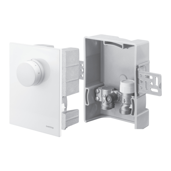
    Le piston de commande ouvre ou ferme le robinet thermostatique selon les besoins. La température ambiante souhaitée peut être réglée en modifiant la position de la poignée Fig. 2: Configuration de l'« Unibox T » manuelle de la tête thermostatique. Choisir la position de montage de l'« Unibox Équerre de fixation T » de telle manière que le fluide passe en pre- Boîtier encastrable mier par le circuit de chauffage et par le robinet de l'« Unibox T » ensuite. Le fluide chauffant se...
  • Page 36: Éléments De Manœuvre

    Description technique Unibox T 3.4 Éléments de manœuvre 3.4.1 Tête thermostatique AVIS Endommagement de la chape lié aux températures inadaptées f Respecter les consignes données par le fabricant de la chape. f Ne pas dépasser la température de la chape à proximité des tubes de chauffage prescrite par la norme DIN 1264-4.
  • Page 37: Données Techniques

    Unibox T Accessoires et pièces de rechange 3.6 Données techniques Transport et stockage Transporter le produit dans son emballage Température 100°C d’origine. de service La température de max. t s Stocker le produit dans les conditions sui- départ de l'instal-...
  • Page 38: Montage De L'« Unibox T

    Montage Unibox T 6.2 Montage de l'« Unibox T » AVIS Dégâts matériels liés aux lubri- Monter l'« Unibox T » de telle ma- fiants nière que le fluide passe en premier par le circuit de chauffage et par le Des graisses et de l’huile peuvent en- robinet de l'« Unibox T » ensuite. dommager les joints. f Ne pas utiliser de graisse ou d’huile lors du montage.
  • Page 39: Mise En Service

    7.2 Préparation de la mise en chauffe Procéder à la mise en chauffe pour vérifier le bon fonctionnement de l'installation de sur- faces chauffantes. Fig. 8: « Unibox T » avec équerres AVIS 5. Raccorder la tuyauterie du circuit de sur- Endommagement de la chape face chauffante à l'« Unibox T ». lié aux températures inadaptées f Réaliser la mise en chauffe des...
  • Page 40: Mise En Chauffe

    Service Unibox T 7.3 Mise en chauffe Procédure de la mise en chauffe : 1. Ouvrir complètement le robinet d'environ un tour à l'aide du capuchon de protection blanc. Régler la température de départ à l'aide de la commande de la chaudière.
  • Page 41 Unibox T Démontage et traitement des déchets Si aucun accord de reprise ou d'élimination n'a été conclu, mettre le produit au rebut. f Si possible, amener les composants au recyclage. f Éliminer les composants non recyclables selon les réglementations locales. L’éli- mination avec les déchets ménagers est interdite.
  • Page 42: Annexe

    Annexe Unibox T 11. Annexe 11.1 Questions fréquentes QUESTION RÉPONSE Deux circuits de chauffage Oui, deux circuits de chauffage de longueur identique peuvent peuvent-ils être raccordés à être raccordés à un même « Unibox T » à l'aide d'une « pièce un même « Unibox T » ? de raccordement - Duo ». Chaque circuit de surface chauffante peut avoir jusqu'à 80 m de longueur de tube, si ce dernier a un diamètre de 16 ou 17 mm.
  • Page 43: Diagramme Des Pertes De Charge

    Unibox T Annexe 11.2 Diagramme des pertes de charge Diagramme des pertes de charge « Unibox T » avec mécanisme «AV 9» avec un écart P de 2 K Préréglage Valeur kv 0,05 0,09 0,12 0,18 0,22 0,28 0,38 0,49 0,57 102272280-V01.02.2020...
  • Page 44: Glossaire

    Glossaire Unibox T 12. Glossaire Robinet bypass Un robinet bypass est un robinet d'arrêt ou d'étranglement utilisé pour contourner un autre composant. Le robinet bypass est installé sur une conduite contournant l'autre composant. Ce robinet a plusieurs objectifs : • Garantir un débit minimal •...
  • Page 48 OVENTROP GmbH & Co. KG Paul-Oventrop-Straße 1 D-59939 Olsberg Telefon +49 (0) 29 62 82-0 Telefax +49 (0) 29 62 82-400 E-Mail mail@oventrop.de Internet www.oventrop.com 102272280 V01.02.2020...

Table des Matières