oventrop Unibox RTL Notice D'utilisation

Régulation de la température de retour
Table des Matières

Publicité

Les langues disponibles

Les langues disponibles

Liens rapides

DE
EN
FR
Premium Armaturen + Systeme
Rücklauftemperaturregelung
Return temperature control
Régulation de la température de retour
Unibox RTL
Betriebsanleitung
Unibox RTL
Operating instructions
Unibox RTL
Notice d'utilisation

Publicité

Table des Matières
loading

Sommaire des Matières pour oventrop Unibox RTL

  • Page 1 Premium Armaturen + Systeme Rücklauftemperaturregelung Unibox RTL Betriebsanleitung Return temperature control Unibox RTL Operating instructions Régulation de la température de retour Unibox RTL Notice d'utilisation...
  • Page 3: Table Des Matières

    Technische Daten ......................9 Zubehör und Ersatzteile ..................9 Transport und Lagerung ................10 Montage ......................10 Allgemeine Montagehinweise ..................10 Montage Unibox RTL ...................... 11 Inbetriebnahme ....................11 Füllen, Entlüften und Dichtheit prüfen ................11 Vorarbeiten Funktionsheizen ................... 12 Funktionsheizen ......................12 Handrad und Abdeckung aufsetzen ................12...
  • Page 4 Demontage und Entsorgung .................15 11.1 Demontage ........................15 11.2 Entsorgung ........................15 Anhang ......................15 12.1 Umbau Unibox RTL (in Einzelraumtemperatur regelung Unibox T) ......... 15 12.2 Unibox RTL verkehrt durchströmt ................... 16 12.3 Thermostatventil tauschen ....................16 12.4 Häufige Fragen ........................ 18 Glossar ......................21...
  • Page 5: Allgemeine Angaben

    Telefon: +49 (0) 29 62 82-234 1.2 Lieferumfang 1.4 Konformitätserklärung Prüfen Sie Ihre Lieferung auf Transportschäden Hiermit erklärt die Oventrop GmbH & Co. KG, und Vollständigkeit. dass dieses Produkt in Übereinstimmung mit Der Lieferumfang umfasst: den grundlegenden Anforderungen und den einschlägigen Bestimmungen der betreffenden...
  • Page 6: Bestimmungsgemäße Verwendung

    Wissenschaft und Technik entspricht und ist gemäßer Verwendung des Produktes gewähr- betriebssicher. Dennoch können bei Montage leistet. und Betrieb Restgefahren für Personen und Die Unibox RTL wird in Warmwasser-Zentral- Sachwerte entstehen. heizungsanlagen mit geschlossenen Kreis- 2.5.1 Gefahr durch unzureichende läufen zur Tempererierung von Boden- und Wandflächen eingesetzt. In einzelnen Räumen...
  • Page 7: Verbrennungsgefahr An Heißen Armaturen Und Oberflächen

    Geben Sie diese Anleitungen und alle mit- Abb. 3: Maße in mm geltenden Anleitungen (z. B. Anleitung des 3.3 Funktionsbeschreibung Zubehörs) an den Betreiber weiter. Die Unibox RTL dient zur Begrenzung der Technische Beschreibung Rücklauftemperatur einer Flächentemperie- rung. Die Einbauposition der Unibox RTL ist 3.1 Aufbau so zu wählen, dass zunächst der Heizkreis...
  • Page 8: Abdeckung Mit Integriertem Handrad

    Technische Beschreibung Unibox RTL Abb. 6: Einstellmöglichkeiten Fühlereinheit Absperrposition Abb. 4: Handrad Frostschutzstellung Montageposition Abdeckung Funktionsheizstellung Temperaturskala Handrad ACHTUNG Beschädigung des Estrich durch falsche Temperaturen! f Befolgen Sie bei sämtlichen Estrichwerkstoffen die Festlegun- gen des Herstellers. f Überschreiten Sie nicht die nach DIN 1264-4 vorgeschriebene Estrichtemperatur in der Nähe der...
  • Page 9: Technische Daten

    Unibox RTL Zubehör und Ersatzteile 3.5 Technische Daten max. Betriebstemperatur t s 100°C max. Betriebsdruck p s 10 bar max. Differenzdruck 1 bar Bautiefe 60 mm Gewindeanschluss Ther­ M30x1,5 mostat Medium Wasser, Wasser-Gly- kol-Gemisch (gemäß VDI 2035; max. 50% Glyko- lanteil) Zubehör und Ersatzteile...
  • Page 10: Transport Und Lagerung

    Montage 6.1 Allgemeine Montagehinweise Vor der Montage sollten Sie folgendes beach- ten: • Die Unterkante der Unibox RTL muss min- destens 20 cm über dem fertigen Fußbo- den liegen. • Die Vorderkante der Unibox RTL muss in einer Ebene mit der fertigen Wand liegen.
  • Page 11: Montage Unibox Rtl

    RTL (siehe Abb. 1 auf Seite 5) wieder auf. 3. Entfernen Sie die Bauabdeckung der Unibox (Sie müssen die Bauabdeckung nach der Inbetriebnahme wieder aufset- zen) und setzen Sie die Unibox RTL an der gewünschten Stelle in die Wand ein. 102273580-V4.06.2020...
  • Page 12: Vorarbeiten Funktionsheizen

    4. Beginnen Sie mit einer Vorlauftemperatur zwischen 20°C bis 25°C über mindestens 3 Tage. 5. Heizen Sie anschließend mit max. Ausle- gungstemperatur über mindestens 4 Tage. 7.4 Handrad und Abdeckung aufsetzen 1. Entfernen Sie nach Abschluss der Bauar- beiten die Bauabdeckung der Unibox RTL. 102273580-V4.06.2020...
  • Page 13: Betrieb

    Die Mediumtemperatur des Flächentemperie- rungskreises stellen Sie mit dem Handrad ein (siehe 3.4.1 auf Seite 7). Die Gegebenheiten vor Ort (z. B. Fliesenstärke) beeinflussen die Temperierung der Fläche. Abb. 14: Mitnehmer am Handrad Mitnehmer 3. Setzten Sie die Abdeckung mit dem integ- rierten Handrad auf die Unibox RTL. 102273580-V4.06.2020...
  • Page 14: Störungen Beheben

    Störungen beheben Unibox RTL Störungen beheben STÖRUNG URSACHE BEHEBUNG Die Flächentemperierung Die Unibox RTL ist im Vorlauf Die Unibox RTL muss von einer wird nicht warm. eingebaut. Rücklauftemperaturbegrenzung in eine Einzelraumtemperaturrege- lung (Unibox T) umgebaut werden (siehe 12.1 auf Seite 15).
  • Page 15: Instandhaltung

    Estrichtemperatur in der Nähe der Heizrohre. f Entsorgen Sie das Verpackungs- material umweltgerecht. Ist die Unibox RTL im Vorlauf eingebaut ist f Entsorgen Sie Bauteile fachge- eine ordnungsgemäße Funktion nicht mehr recht. gegeben. Sie müssen die Unibox RTL von einer Rücklauftemperaturbegrenzung in eine...
  • Page 16: Unibox Rtl Verkehrt Durchströmt

    Anhang Unibox RTL 12.2 Unibox RTL verkehrt durchströmt Die Unibox RTL gibt Schlaggeräusche von sich, wenn Sie verkehrt herum durchströmt wird. Abb. 17: Thermostat RTL abschrauben 3. Wechseln Sie den Ventileinsatz des Thermostatventil RTL, verwenden Sie die Artikelnummer 1187047. 4. Schrauben Sie den Thermostat Uni LH Abb.
  • Page 17 12.4 Justierung des Thermostat RTL (Fühlereinheit) Der Thermostat RTL (Fühlereinheit) ist werksseitig justiert. Eine einwandfreie Funktion der Unibox RTL ist nur bei korrekter Justierung gegeben. Sollten Sie die Justierung verstellt haben, nehmen Sie die folgenden Schritte vor um die Justierung wieder herzustellen (siehe Abb. 21 auf Seite 17): •...
  • Page 18: Häufige Fragen

    Abb. 23: Anschlussschema zwei Heizkreise mit Duo-An- schlussstück Wie viel m² Flächentemperie- Pro Unibox RTL können Sie ca. 20 m² Fläche anschließen. Die rung kann ich an die Unibox Rohrlänge darf max. 100 m betragen bei einem 17er Rohr. RTL anschließen? Kann die Unibox RTL mit Nein, Stellantriebe sind nur für Uniboxen mit Einzelraumrege-...
  • Page 19 Unibox RTL Anhang FRAGE ANTWORT Kann ich die Unibox RTL Die Unibox RTL ist für Einrohrheizungsanlagen geeignet. auch bei einer Einrohrheizung Möglichkeit 1: verwenden? Abb. 24: Anschluss mit Bypass-Ventil und Heizkörperver- schraubung mit Bypass Bypass-Ventil Heizkörperverschraubung mit Bypass Der Volumenstrom und Druckverlust können sich erhöhen.
  • Page 20 Anhang Unibox RTL FRAGE ANTWORT - Der Volumenstrom und Druckverlust können sich erhöhen. - Beachten Sie den Druckverlust der Heizkörperarmaturen. - Regulieren Sie das Bypass-Ventil so ein, dass genug Wasser durch die Flächentemperierung fließt. - Am Heizkörper dürfen keine Geräusche entstehen. Möglichkeit 3: Abb.
  • Page 21 Unibox RTL Anhang 12.6 Durchflussdiagramm 102273580-V4.06.2020...
  • Page 22: Glossar

    13. Glossar Bypass­Ventil Ein Bypass-Ventil ist ein Absperr- oder Drosselventil, das eingesetzt wird um ein anderes Bauteil zu umgehen. Das Bypassventil ist in einer Leitung verbaut, welche das andere Bauteil umgeht. Mit dem Einbau dieses Ventils werden verschiedene Ziele verfolgt: •...
  • Page 25 Accessories and spare parts ................31 Transport and storage ...................32 Installation ......................32 General installation advice ....................32 Installation of the Unibox RTL ..................33 Commissioning ....................33 Filling, bleeding and leak testing ..................33 Preliminary work for incremental heating test ..............34 Incremental heating test ....................
  • Page 26 11.1 Removal .......................... 37 11.2 Disposal ........................... 37 Appendix ......................37 12.1 Conversion of the Unibox RTL (to individual room temperature control Unibox T) ..37 12.2 Wrong flow against the Unibox RTL ................38 12.3 Replacement of the thermostatic valve ................38 12.4 Calibration of the thermostat RTL (sensor unit)............... 39 12.5...
  • Page 27: General Information

    Unibox RTL. 1.4 Declaration of conformity 1.2 Extent of supply Oventrop GmbH & Co. KG hereby declares that Please check your delivery for any damage this product complies with the basic require- caused during transit and for completeness.
  • Page 28: Safety-Related Information

    We have developed this product in accordance uct is used correctly. with current safety requirements. Please ob- serve the following notes concerning safe use. The Unibox RTL is used in hot water central heating systems with closed circuits for tem- 2.5.1 Danger caused by inadequately perature balancing of floor and wall surfaces. It...
  • Page 29: Availability Of The Operating Instructions

    3.1 Design system. The installation position of the Unibox RTL has to be chosen so that heating fluid passes first through the heating circuit and then through the valve of the Unibox RTL. On its way from the entry into the heating surface to the Unibox RTL, the heating fluid cools down. The fluid temperature is controlled by adapting the flow rate. The return temperature is set at the handwheel of the thermostat. You can modify the surface temperature by turning the handwheel.
  • Page 30: Cover With Integrated Handwheel

    Technical description Unibox RTL Illust. 6: Setting options of the sensor unit Shut-off position Illust. 4: Handwheel Frost protection position Installation position Cover Incremental heating position Temperature scale Handwheel NOTICE Damage to the screed as a re­ sult of incorrect temperatures f Observe the instructions of the screed manufacturer.
  • Page 31: Technical Data

    Unibox RTL Accessories and spare parts 3.5 Technical data Max. operating tempera­ 100°C ture t s Max. operating pressure p s 10 bar Max. differential pressure 1 bar Installation depth 60 mm Thermostat and actuator M30x1.5 connection thread Fluid Water, mix-...
  • Page 32: Transport And Storage

    Installation 6.1 General installation advice Note the following prior to installation: • The lower edge of the Unibox RTL must be at least 20 cm above the finished floor. • The front face of the Unibox RTL must be level with the finished wall. Should the wall not have been finished, take the plaster and tile Illust.
  • Page 33: Installation Of The Unibox Rtl

    5. Connect the pipework of the surface temperature regulation circuit to the Unibox RTL. Observe the marked flow direction. Illust. 10: Connection 6. Provide a connecting pipe between the Unibox RTL and the return pipe of the two Radiator pipe heating system. Unibox RTL Commissioning Surface temperature regulation circuit Supply 7.1 Filling, bleeding and leak...
  • Page 34: Preliminary Work For Incremental Heating Test

    Commissioning Unibox RTL NOTICE Damage to the screed as a re­ sult of incorrect temperatures f Carry out the incremental heating test of concrete and calcium sul- phate screed in accordance with DIN EN 1264-4. f Observe the instructions of the Illust.
  • Page 35: Operation

    (see section 3.4.1 on page 29). Surface temperature regulation is affected by the local conditions (such as tile thickness). Illust. 14: Locating groove at the handwheel Locating groove 3. Fit the cover with the integrated handwheel to the Unibox RTL. 102273580-V4.06.2020...
  • Page 36: Troubleshooting

    Troubleshooting Unibox RTL Troubleshooting MALFUNCTION CAUSE REMEDY The surface temperature The Unibox RTL is installed in Convert the Unibox RTL from a regulation circuit does not the supply. return temperature limitation to an get warm. individual room temperature con- trol (Unibox T) (see section 12.1 on page 37).
  • Page 37: Maintenance

    Dispose of the components appro- If the Unibox RTL is installed in the supply pipe, priately. correct functioning is no longer guaranteed. You have to convert the Unibox RTL from a return...
  • Page 38: Wrong Flow Against The Unibox Rtl

    "RTL" with the valve insert item no. 1187047. 4. Screw the thermostat Uni LH (item no. Illust. 19: Wrong flow against the Unibox RTL 1011465, white or item no. 1011469, 12.3 Replacement of the chrome plated) onto the valve.
  • Page 39: Calibration Of The Thermostat Rtl (Sensor Unit)

    12.4 Calibration of the thermostat RTL (sensor unit) The thermostat RTL (sensor unit) is factory cal- ibrated. A perfect function of the Unibox RTL is only guaranteed if it is correctly calibrated. Should you have changed the calibration, pro- ceed as follows to recalibrate the thermostat (see Illust.
  • Page 40: Faqs

    Is it possible to connect two Yes, use a Duo connection piece to connect two heating cir- heating circuits to one Unibox cuits of the same length to one Unibox RTL. Each surface tem- RTL? perature regulation circuit may have a maximum pipe length of 80 m, provided you use 16/17 mm pipes.
  • Page 41 Unibox RTL Appendix QUESTION RESPONSE Can I also use the Unibox RTL The Unibox RTL is suitable for one pipe heating systems. in a one pipe heating system? Option 1: Illust. 24: Connection with bypass valve and radiator fitting with bypass...
  • Page 42 Appendix Unibox RTL QUESTION RESPONSE - The volume flow and pressure loss may increase. - Observe the pressure loss of the radiator fittings. - Adjust the bypass valve so that a sufficient quantity of water passes through the surface temperature regulation circuit. - No noise must be perceivable at the radiator. Option 3: Illust. 26: Connection with Unibox RLA Unibox RLA Bypass valve - The volume flow and pressure loss may increase.
  • Page 43: Flow Chart

    Unibox RTL Appendix 12.6 Flow chart 102273580-V4.06.2020...
  • Page 44: Glossary

    13. Glossary Bypass valve A bypass valve is an isolating or throttling valve that is used to bypass another component. The bypass valve is installed in a pipe that bypasses the other component. Installation of this valve pursues different objectives: •...
  • Page 47 Accessoires et pièces de rechange .............53 Transport et stockage ...................54 Montage ......................54 Instructions générales de montage ................. 54 Montage de l'Unibox RTL ....................55 Mise en service ....................55 Remplissage, purge et test d'étanchéité ................. 55 Préparation de la mise en chauffe ................... 56 Mise en chauffe .......................
  • Page 48 11.2 Traitement des déchets ....................59 Annexe ......................59 12.1 Conversion de de l'Unibox RTL (en une régulation de la température par pièce Unibox T) 12.2 Inversion du sens du débit dans l'Unibox RTL ............... 60 12.3 Remplacement du robinet thermostatique ..............60 12.4...
  • Page 49: Généralités

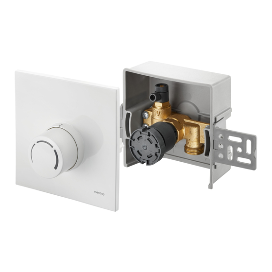
    1.4 Déclaration de conformité Les composants fournis sont les suivants : Par la présente, la société Oventrop GmbH & • Unibox RTL avec capot de protection pour Co. KG déclare que ce produit est en confor- le montage mité avec les exigences fondamentales et les dispositions applicables des directives UE •...
  • Page 50: Modifications Sur Le Produit

    Informations relatives à la sécurité Unibox RTL 2.5.1 Danger lié à un manque de des surfaces de plancher et de mur. Dans des pièces individuelles il limite la température du qualification fluide d'un circuit de radiateur. Les interventions sur le produit doivent être Toute autre utilisation est interdite et réputée réservées à un professionnel qualifié.
  • Page 51: Disponibilité De La Notice D'utilisation

    Encombrements en mm de l'installation. 3.3 Description du fonctionnement Description technique L'Unibox RTL sert à la limitation de la tempé- rature de retour d'un système de régulation de 3.1 Configuration température de surfaces. Choisir la position de montage de l'Unibox RTL de telle manière...
  • Page 52: Capot Avec Poignée Manuelle Intégrée

    Description technique Unibox RTL conséquence. Fig. 6: Options de réglage de l'unité de capteur Position de fermeture Fig. 4: Poignée manuelle Position hors-gel Position de montage Capot Position de mise en chauffe Échelle de température AVIS Poignée manuelle Endommagement de la chape lié...
  • Page 53: Données Techniques

    Unibox RTL Accessoires et pièces de rechange 3.5 Données techniques Température de service 100°C max. t s Pression de service max. 10 bar Pression différentielle max. 1 bar Profondeur 60 mm Raccordement fileté de la M30x1,5 tête thermostatique et du...
  • Page 54: Transport Et Stockage

    6.1 Instructions générales de montage Tenir compte des instructions suivantes avant de procéder au montage : • Le bord inférieur de l'Unibox RTL doit se si- tuer au moins 20 cm au-dessus du sol fini. • La façade avant de l'Unibox RTL doit se Fig. 9: Vue en coupe de l'installation situer au même niveau que le mur fini. Si le mur n'est pas encore fini, res- pecter l'épaisseur prévue de plâtre Unibox RTL et des carreaux.
  • Page 55: Montage De L'unibox Rtl

    Unibox RTL Mise en service 6.2 Montage de l'Unibox RTL l'Unibox RTL dans le mur à l'endroit voulu. L'Unibox RTL doit toujours se si- Utiliser une gaine encastrable pour tuer à la fin du circuit de régulation faciliter le montage. de température de surfaces (voir 3.3 en page 51).
  • Page 56: Préparation De La Mise En Chauffe

    Mise en service Unibox RTL AVIS Endommagement de la chape lié aux températures inadaptées f Réaliser la mise en chauffe des chapes de ciment et de sulfate de calcium selon la norme DIN EN 1264-4. f Respecter les consignes données Fig.
  • Page 57: Service

    (voir 3.4.1 en page 51). La régulation de température de surfaces est influencée par les conditions sur site (par ex. épaisseur des carreaux). Fig. 14: Profil aux rainures sur la poignée manuelle Profil aux rainures 3. Monter le capot avec poignée manuelle intégrée sur l'Unibox RTL. 102273580-V4.06.2020...
  • Page 58: Réparation Des Dysfonctionnements

    Réparation des dysfonctionnements DYSFONCTIONNE­ CAUSE DÉPANNAGE MENT Le système de régulation L'Unibox RTL est monté sur L'Unibox RTL doit être converti de température de sur- l'aller. d'une limitation de la température faces ne chauffe pas. de retour en une régulation de la température par pièce Unibox T...
  • Page 59: Maintenance

    Éliminer l’emballage dans le res- DIN 1264-4. pect de l’environnement. f Éliminer les composants dans le Si l'Unibox RTL est installé sur l'aller, un bon respect de la réglementation. fonctionnement n'est plus garanti. Vous devez convertir l'Unibox RTL d'une limitation de la Si aucun accord de reprise ou d'élimination n'a...
  • Page 60: Inversion Du Sens Du Débit Dans L'unibox Rtl

    Annexe Unibox RTL 12.2 Inversion du sens du débit dans l'Unibox RTL L'Unibox RTL fait des bruits de battement en cas d'inversion du sens du débit. Fig. 17: Démontage de la tête thermosta- tique RTL 3. Remplacer le mécanisme du robinet thermostatique RTL par le mécanisme réf.
  • Page 61: Ajustage De La Tête Thermostatique Rtl (Unité De Capteur)

    Unibox RTL Annexe Tête thermostatique RTL (unité de capteur) Trait de repère 12.4 Ajustage de la tête thermostatique RTL (unité de capteur) La tête thermostatique RTL (unité de capteur) est ajustée en usine. Un ajustage correct et la condition pour le bon fonctionnement de l'Unibox RTL.
  • Page 62: Questions Fréquentes

    RÉPONSE Deux circuits de chauffage Oui, deux circuits de chauffage de longueur identique peuvent peuvent-ils être raccordés à être raccordés à un même Unibox RTL à l'aide d'une pièce de un même Unibox RTL ? raccordement Duo. Chaque circuit de régulation de tempéra- ture de surfaces peut avoir jusqu'à 80 m de longueur de tube, si ce dernier a un diamètre de 16 ou 17 mm.
  • Page 63 Unibox RTL Annexe QUESTION RÉPONSE Est-il possible d'utiliser l'Uni- L'Unibox RTL peut être utilisé dans des installations de chauf- box RTL dans une installation fage monotubes. de chauffage monotube ? Option 1 : Fig. 24: Raccordement avec robinet bypass et raccord de radiateur avec bypass...
  • Page 64 Annexe Unibox RTL QUESTION RÉPONSE - Le débit et la perte de charge peuvent augmenter. - Respecter la perte de charge de la robinetterie de radiateur. - Réajuster le robinet bypass pour qu'une quantité suffisante d'eau circule dans le système de régulation de température de surfaces. - Le radiateur ne doit faire aucun bruit.
  • Page 65: Digramme De Débit

    Unibox RTL Annexe 12.6 Digramme de débit Écart P Débit 102273580-V4.06.2020...
  • Page 66: Glossaire

    Glossaire Unibox RTL 13. Glossaire Robinet bypass Un robinet bypass est un robinet d'arrêt ou d'étranglement utilisé pour contourner un autre composant. Le robinet bypass est installé sur une conduite contournant l'autre composant. Ce robinet a plusieurs objectifs : • Réglage d'un débit nécessaire...
  • Page 68 OVENTROP GmbH & Co. KG Paul-Oventrop-Straße 1 59939 Olsberg DEUTSCHLAND 102273580 V4.06.2020 www.oventrop.com...

Table des Matières