Télécharger Imprimer la page

Publicité

Les langues disponibles
  • FR

Les langues disponibles

Liens rapides

Betriebsanleitung
für Drehfutter, handbetätigt, zentrisch spannend
und einzelverstellbar und für Planscheiben
GB
Operating
instructions
for
manually operated, self-center-
ing and independently adjust-
able lathe chucks and for face
plates
UGE/UGU
USE/USU
ZG/ZS
ZGU/ZSU
ZG HiTru
EG/ES
Stand: 02/06
Stand: 11/04
ZG-Gußkörper, ZS-Stahlkörper mit nach innen und außen abgestuften Backen -- ZGU-Gußkörper, ZSU-Stahlkörper mit gehärteten Grund- und gehärteten oder weichen Aufsatzbacken
ZGF-Gußkörper, Zweibackenfutter mit gehärteten Grund- und weichen Aufsatzbacken -- ZGD-Gußkörper, Dreibackenfutter mit doppelter Backenführung
Dreh- und Schleiffutter ZG Hi-Tru Gußkörper, mit nach innen und außen abgestuften Backen -- EG-Gußkörper, ES-Stahlkörper Drei- und Vierbackenfutter
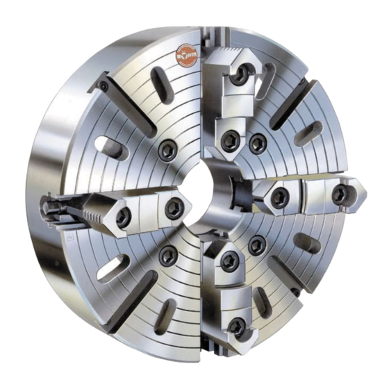
Planscheiben, UGE/UGU Gußkörper, USE/USU Stahlkörper
ZG cast iron body, ZS steel body with jaws stepped inward and outward -- ZGU cast iron body, ZSU steel body with hardened base and hardened or soft top jaws
ZGF cast iron body, 2-jaw chucks with hardened base and soft top jaws -- ZGD cast iron body, 3-jaw chuck with double jaw guide
Lathe and grinding chucks ZG Hi-Tru, cast iron bodies with jaws stepped inward and outward -- EG cast iron body, ES steel body, 3-jaw and 4-jaw chucks
Independent chucks, UGE/UGU cast iron body, USE/USU steel body
ZG corps en fonte, ZS corps en acier, avec mors étagés vers l'intérieur et vers l'extérieur --
ZGU corps en fonte, ZSU corps en acier, avec mors sur semelles trempés et mors rapportés trempés ou doux
ZGF corps en fonte, mandrin à deux mors avec mors à semelles trempés et mors rapportés doux
Mandrin de tour et de rectifieuse ZG Hi-Tru, corps en fonte, avec mors étagés vers l'intérieur et vers l'extérieur -- EG corps en fonte, ES corps en acier, mandrin à 3 et 4 mors
Plateaux circulaires, UGE/UGU corps en fonte, USE/USU corps en acier
Cuerpo de fundición ZG, cuerpo de acero ZS con garras escalonadas hacia adentro y hacia afuera --
Cuerpo de fundición ZGU, cuerpo de acero ZSU con garras base templadas y mordazas superpuestas templadas o blandas
Cuerpo de fundición ZGF, plato de dos garras con garras básicas templadas y mordazas superponibles blandas -- Cuerpo de fundición ZGD, plato de cuatro garras con doble guía de garras
Plato para torno y para rectificadora ZG Hi-Tru, cuerpo de fundición con garras escalonadas hacia dentro y hacia afuera -- Cuerpo de fundición EG, cuerpo de acero ES, platos de tres y cuatro garras
Platos de cuatro garras, cuerpo de fundición UGE/UGU, cuerpo de acero USE/USU
ZG corpo fuso, ZS corpo d'acciaio con griffe a gradini verso l'interno e verso l'esterno -- ZGU corpo fuso, ZSU corpo d'acciaio con griffe base temprate e griffe riportate temprate o dolci
ZGF corpo fuso, mandrino a due griffe con griffe base temprate e griffe riportate dolci -- ZGD corpo fuso, mandrino a tre griffe con doppia guida delle griffe
Mandrino da tornio e da rettifica ZG Hi-Tru corpo fuso, con griffe a gradini verso l'interno e verso l'esterno -- EG corpo fuso, ES corpo d'acciaio, mandrino a 3 e 4 griffe
Piattaforme, UGE/UGU corpo fuso, USE/USU corpo d'acciaio
F
Notice d'utilisation pour man-
drins de tour à commande man-
uelle, à serrage concentrique et
réglage individuel, et pour pla-
teaux circulaires
UGE/UGU
USE/USU
E
Instrucciones de empleo para
platos de torno de acciona-
miento manual, sujeción auto-
centrante y de regulación indi-
vidual, y para platos de cuatro
mordazas
ZG/ZS
EG/ES
I
Istruzioni d'uso per mandrini au-
tocentranti per tornio, con co-
rona, ad azionamento manuali,
serraggio concentrico, e per
piattaforme
ZGU/ZSU
ZG HiTru
RN-398

Publicité

loading

Sommaire des Matières pour Rohm UGE/UGU

  • Page 1 Plato para torno y para rectificadora ZG Hi-Tru, cuerpo de fundición con garras escalonadas hacia dentro y hacia afuera -- Cuerpo de fundición EG, cuerpo de acero ES, platos de tres y cuatro garras Platos de cuatro garras, cuerpo de fundición UGE/UGU, cuerpo de acero USE/USU ZG corpo fuso, ZS corpo d’acciaio con griffe a gradini verso l’interno e verso l’esterno -- ZGU corpo fuso, ZSU corpo d’acciaio con griffe base temprate e griffe riportate temprate o dolci...
  • Page 2 1. Sicherheitshinweise und Richtlinien für den Einsatz von handbetätigten Spanneinrichtungen I. Qualifikation des Bedieners von asymmetrischen Werkstücken oder bei Verwendung unter- Personen, welche keine Erfahrungen im Umgang mit Spannein- schiedlicher Aufsatzbacken. richtungen aufweisen, sind durch unsachgemäßes Verhalten, vor Um daraus entstehende Schäden zu verhindern, ist das Futter allem während der Einrichtarbeiten durch die auftretenden Spann- mit Werkstück möglichst dynamisch entsprechend der DIN ISO bewegungen und --kräfte, besonderen Verletzungsgefahren aus-...
  • Page 3 Sicherheitshinweise und Richtlinien für den Einsatz von handbetätigten Spanneinrichtungen Sollen neue Spannsätze auf der Maschine in Betrieb genom- verzichtet werden können, so muß bei Spannwegen größer men werden, so istzuvor die Zulässigkeit zu prüfen. Hierun- als 4 mm ter fallen auch vom Anwender selbst gefertigte Spannsätze -- eine fest-- oder vorübergehend angebaute Werkstückhalte- bzw.
  • Page 4 Sicherheitshinweise und Richtlinien für den Einsatz von handbetätigten Spanneinrichtungen Durch äußere Einflüsse, wie z.B. Vibrationen, können sich unter Falsch Richtig Umständen selbst fest angezogene Schrauben lösen. Um dies zu verhindern, müssen alle sicherheitsrelevanten Schrauben (Spann- mittelbefestigungsschrauben, Spannsatzbefestigungsschrauben u. Zu kurze Einspannlänge, Zusätzliche Abstützung ä.) in regelmäßigen Zeitabständen kontrolliert und ggf.
  • Page 5 Drehfutter ZG-ZS, ZGU-ZSU, ZGF und ZGD Drehfutter ZG-ZS, ZGU-ZSU, ZGF und ZGD mit zylindrischer Zentrieraufnahme mit Kurzkegel-Aufnahme Drehfutter ZG Hi-Tru Drehfutter EG-ES Planscheibe UGE-UGU, USE-USU mit zylindrischer Zentrieraufnahme Körper Stiftschraube Deckel--Befestigungsschraube Grundbacke Deckel Bohrbacke Flansch Umkehrbacken Spiralring Drehbacke Flanschbefestigungsschraube Umkehr-Aufsatzbacken Trieb Befestigungsschraube Verstellspindel...
  • Page 6 Max. zulässige Drehzahl für Spannkraft bei 3-Backen-Dreh- Drehfutter ZG-ZS, ZGU-ZSU futtern ZG-ZS, ZGU-ZSU und Größe 3-und 4-Backen Größe Drehmo- Gesamt- und ZG Hi-Tru nach DIN 6350 ZG Hi-Tru nach DIN 6350 ment am spann- Guß- Stahl- sowie EG/ES nach DIN 6351 Schlüssel kraft körper...
  • Page 7 bez. auf die Bezugsflächen für die Futteraufnahme (gültig für alle Futtertypen, jedoch nicht für ZGF und EG/ES) Rundlauftoleranz T Prüfung Klasse I Klasse II dünn mittel dick (74) nach Vereinbarung 0,05 0,04 (85) 0,04 0,02 (110) (140) 0,075 0,04 0,04 0,03 (230) 0,06...
  • Page 8 3. Montage des Drehfutters auf den Maschinen-Spindelkopf (gültig für alle Futtertypen und Planscheiben) 3.1 Aufsetzen des Drehfutters auf Drehspindel mit Kurzkegel 3.1.4 Befestigungselemente gleichmäßig über Kreuz fest an- ziehen (Tabelle 1) Kurzkegel und Plananlage des Futters müssen nach Montage an der Spindelnase gleichmäßig tragen! 3.1.1 Kegelaufnahme und Plananlage des Futters sowie Ma- 3.1.5 Bei der Montage des Futters auf Drehspindeln mit Cam- schinenspindel sorgfältig reinigen.
  • Page 9 Planscheiben (Unabhängige Vierbackenfutter) UGE/USE mit einteiligen Umkehrbacken -- UGU/USU mit Umkehr-Aufsatzbacken Zur Grobzentrierung dienen die eingearbeiteten kon- Backen an der Planscheibe herausgedreht und die zentrischen Ringe, die Feinzentrierung muß mit der Spannung mit Spannpratzen und Schrauben direkt in Meßuhr erfolgen. Dabei beachten, daß die Zustellung der Planscheibe erfolgen.
  • Page 10 1. Safety requirements and rules and regulations for the use of manually operated chucks I. Qualification of the operating staff Persons, who have no experience in handling clamping equip- ment, run the risk of being injured by the clamping motions and In order to prevent the occurrence of any damage, the chuck forces occurring as a result of incorrect behaviour, especially du- and the work piece should be balanced dynamically in accor-...
  • Page 11 Safety requirements and rules and regulations for the use of manually operated chucks If new clamping sets are to be taken into operation on the For this reason, the drive equipment provided for the chuck machine, the admissibility must be previously checked. This actuation shall have to be switched off explicitly for all mounting also includes clamping sets or clamping set components and setting work as a matter of principle.
  • Page 12 Safety requirements and rules and regulations for the use of manually operated chucks for refitting work), have to be covered with an anti--seize agent Wrong Right (grease paste) in the thread area and the head contact area in intervals of six months. Under certain circumstances environmental influences, i.
  • Page 13 Operating instructions Lathe chuck ZG-ZS, ZGU-ZSU, ZGF and ZGD Lathe chuck ZG-ZS, ZGU-ZSU, ZGF and ZGD with cylindrical centring rim with short taper mounting Lathe chuck ZG Hi-Tru Lathe chuck EG-ES Face plate UGE-UGU, USE-USU Chuck body Stud bolt Backplate mounting screw Base jaw Backplate Drilling jaw...
  • Page 14 Max. permissible speed for la- Gripping force for 3-jaw lathe the chucks ZG-ZS, ZGU-ZSU chucks ZG-ZS, ZGU-ZSU and Size 3 and 4-jaw chucks Size Torque Total and ZG Hi-Tru in accordance ZG Hi-Tru in accordance with at the gripping with DIN 6350 Cast iron Steel DIN 6350 and EG/ES in accor-...
  • Page 15 Concentricity tolerance T relative to the reference surfaces for chuck fitting (valid for all chuck types, but not for ZGF and EG/ES) Test Class I Class II Thin Medium Thick (74) as agreed 0,05 0,04 (85) 0,04 0,02 (110) (140) 0,075 0,04 0,04...
  • Page 16 3. Mounting the chuck on the machine spindle head (valid for all chuck types and face plates) 3.1 Mounting the chuck lathe on lathe spindles with short taper 3.1.4 Firmly tighten the fastening elements to an even torque in diagonally opposite pairs. (table 1) 3.1.1 Carefully clean the taper seat and contact surface of the Both the short taper and the face of the chuck must...
  • Page 17 Face plates (four-jaw independent chucks) UGE/USE with single-piece reversible jaws -- UGU/USU with reversible top jaws The jaws cen be centered approximately by adjusting be backed out and removed from the faceplate and re- them to the concentric grooves around the face of the placed by clamps and bolts which hold the workpiece di- chuck body.
  • Page 18 1. Indications concernant la sécurité et directives pour l’emploi des mandrins de tours à commande manuelle I.Qualification de l’utilisateur portés différents. Afin d’éviter des dégradations, le mandrin doit, si Toute personne ne possédant pas d’expérience dans la manipulation possible, être équilibré de façon dynamique avec la pièce con- de dispositifs de serrage est mise en garde contre toute formément à...
  • Page 19 Indications concernant la sécurité et directives pour l’emploi des mandrins de tours à commande manuelle Si de nouveaux inserts de serrage doivent être mis en route sur Toutefois, si un mouvement de serrage s’avère nécessaire dans le la machine, il convient tout d’abord de vérifier la fiabilité. Dans ce cas d’un réglage, il faut, pour des courses de serrage supérieures cas de figure, on considère également les inserts ou pièces de à...
  • Page 20 Indications concernant la sécurité et directives pour l’emploi des mandrins de tours à commande manuelle Mauvais 13. Travaux d’entretien La fiabilité du dispositif de serrage ne peut être garantie que si Longeur de serrage trop Appui supplémentaire par les consignes d’entretien mentionnées dans les instructions de courte, longeur de saillie la pointe ou la lunette service sont scrupuleusement suivies.
  • Page 21 Notice d’utilisation Mandrin de tour ZG-ZS, ZGU-ZSU, ZGF et ZGD Mandrin de tour ZG-ZS, ZGU-ZSU, ZGF et ZGD avec fixation par centrage cylindrique avec fixation sur cône court Mandrin de tour ZG Hi-Tru Mandrin de tour EG-ES Plateau circulaire UGE-UGU, USE-USU avec fixation par centrage cylindrique Corps Goujon...
  • Page 22: Mise En Place Des Éléments De Fixation Du Mandrin

    Vitesse de rotation max. admis- Force de serrage dans le cas de sible pour mandrins de tour mandrins de tour à 3 mors ZG- Taille 3 et 4 mors Taille La couple Force de ZG-ZS, ZGU-ZSU et ZG Hi-Tru ZS, ZGU-ZSU et ZG Hi-Tru, se- de serrage serrage à...
  • Page 23 Tolérance de concentricité T par rapport aux surfaces de référence pour le montage du mandrin (valable pour tous les types de mandrins, mais pas pour ZGF ni EG/ES) Contrôle Catégorie I Catégorie II Faible Moyen Fort (74) Suivant accord 0,05 0,04 (85) 0,04...
  • Page 24 3. Montage du mandrin de tour sur la tête porte-broche de la machine (valable pour tous les types de mandrins et plateaux circulaires) 3.1 Mise en place du mandrin de tour sur broche de tour sur bro- 3.1.4 Serrer à fond et régulièrement, en croix, les éléments de fixation.
  • Page 25 Plateaux circulaires (mandrins à quatre mors indipendants) UGE/USE avec mors réversible en une partie -- UGU/USU avec mors rapporté réversible Pour le centrage sommaire, on utilise les anneaux con- serrage être effectué à l’aide de pattes de serrage et de centriques noyés, tandis que le centrage précis doit être vis, directement dans le plateau circulaire.
  • Page 26 1. Istrucciones de seguridad y directrices para el empleo de platos de torno accionados manualmente I. Competencia del operador El empleo de otros/adicionales juegos de sujeción/piezas Personas que no tienen experiencias con el manejo de dispositivos de a trabajar sujeción están expuestas de manera especial a peligros de lesiones a Para el empleo de insertos de sujeción resp.
  • Page 27 Istrucciones de seguridad y directrices para el empleo de platos de torno accionados manualmente 4. La sujeción de otras / adicionales piezas a trabajar ¡La forma de este dispositivo de ajuste auxiliar por principio Si para este dispositivo de sujeción se han previsto juegos depende de la máquina de mecanización empleada, y en caso de sujeción especiales (mordazas, insertos de sujeción, dado deberá...
  • Page 28 Istrucciones de seguridad y directrices para el empleo de platos de torno accionados manualmente Incorrecto Correcto presión de introducción. Por lo que, en caso dado, se habrá de utilizar una engrasadora de alta presión). Longitud de sujeción muy Apoyo adicional medi- -- Para la distribución de grasa favorable en la lubricación corta, valadizo muy largo ante contrapunto o luneta...
  • Page 29: Instrucciones De Empleo

    Instrucciones de empleo Plato de torno ZG-ZS, ZGU-ZSU, ZGF y ZGD Plato de torno ZG-ZS, ZGU-ZSU, ZGF y ZGD con sujeción autocentrante cilíndrica de cono corto Plato de torno de fundición ZG Hi-Tru Plato de torno EG-ES Plato de cuatro garras independientes UGE-UGU, USE-USU con fijación auto- centrante Cuerpo...
  • Page 30 Velocidad máxima de giro ad- Fuerza de sujeción en platos de misible para platos de torno de torno de 3 mordazas de ZG-ZS, Tamaño 3 y 4 garras Tamaño Par en Fuerza ZG-ZS, ZGU-ZSU y ZG Hi-Tru ZGU-ZSU y ZG Hi-Tru según llave en total según DIN 6350...
  • Page 31 Tolerancia de concentricidad T referida a las superficies de referencia para la fijación del plato de torno (válido para todos los tipos de plato de torno, pero no para ZGF y EG/ES) Verificación Categoría I Categoría II Fino Medio Grueso (74) A determinar por mutuo acuerdo 0,05...
  • Page 32 3. Montaje del plato en el cabezal del husillo de la máquina (válido para todos los tipos de platos) 3.1 Colocación del plato de torno sobre el husillo giratorio con 3.1.4 Apretar firmemente los elementos de sujeción uniforme- mente en cruz cono corto (Tabla 1) ¡( El cono corto y el apoyo plano del plato deben so-...
  • Page 33 Platos de cuatro (garras independientes) UGE/USE con garras reversibles en una sola pieza -- UGU/USU con garras reversibles postizas Para el centraje basto se emplean los aros concentricos tor- pendiente y puede realizarse la sujeción con bridas de suje- neados, debiendo realizarse el centraje de precisión con el ción y tornillos directamente en el plato de 4 mordazas.
  • Page 34 1. Avvertenze riguardanti la sicurezza operativa di attrezzature di serraggio ad azionamento manuale I. Qualifica dell’operatore compensazione della rotazione, vedere § 6.2 N e) della norma Le persone che non dispongono di esperienza nell’impiego delle EN 1550. Questo vale in particolar modo per gli elevati regimi di attrezzature di serraggio sono esposte, in seguito a comportamenti rotazione, per la lavorazione di pezzi asimmetrici o per l’impiego di inadeguati, a particolari pericoli di lesioni, soprattutto durante i lavori...
  • Page 35 Avvertenze riguardanti la sicurezza operativa di attrezzature di serraggio ad azionamento manuale 3. Pericolo dovuto ad eventuali espulsioni 10. Montaggio e messa a punto Per proteggere l’operatore dai pezzi espulsi, deve essere pre- I movimenti di serraggio, eventuali movimenti di messa a punto ecc., sente sulla macchina utensile una barriera di protezione con- rappresentano brevi corse eseguite in tempi brevi sotto l’azione di forme alle norme DIN EN 12415, la cui capacità...
  • Page 36 Avvertenze riguardanti la sicurezza operativa di attrezzature di serraggio ad azionamento manuale Sostituendo le viti originali, in caso di dubbio deve essere utilizzata la Errato Corretto classe di vite 12.9. Nel caso di viti di fissaggio per elementi di bloccag- gio, ganasce di applicazione, impianti fissi, coperchio cilindrico ed elementi Serraggio troppo corto Supporto addizionale utiliz-...
  • Page 37 Istruzioni d’uso Mandrini per tornio ZG-ZS, ZGU-ZSU, ZGF e ZGD Mandrini per tornio ZG-ZS, ZGU-ZSU, ZGF e ZGD con attacco di centraggio cilindrico con attacco a cono corto Mandrini per tornio ZG Hi-Tru Mandrini per tornio EG-ES Piattaforme UGE-UGU, USE-USU con attacco di centraggio cilindrico corpo vite prigioniera...
  • Page 38 Max. numero di giri ammesso Forza di serraggio per mandrini per mandrini per tornio ZG-ZS, per tornio a tre griffe ZG-ZS, Grandezza 3 e 4 griffe Grandezza coppia forza di ZGU-ZSU e ZG Hi-Tru a norme ZGU-ZSU e ZG Hi-Tru a norme sulla serraggio DIN 6350...
  • Page 39 Tolleranza di oscillazione radiale T in rapporto alle superfici di riferimento per l’attacco del mandrino (valido per tutti i tipi di mandrino, però non per ZGF e EG/ES) Controllo Classe I Classe II sottile medio spesso (74) secondo accordi 0,05 0,04 (85) 0,04...
  • Page 40 3. Montaggio del mandrino per tornio sulla testa portamandrino della macchina (valido per tutti i tipi di mandrino e per tutte le piattaforme) 3.1 Applicazione del mandrino sull’albero con cono corto (Tabella 1) 3.1.4 Serrare saldamente a croce in modo uniforme gli ele- 3.1.1 Pulire con cura l’attacco conico e il piano di appoggio del menti di serraggio.
  • Page 41 Piattaforme (mandrini indipendenti a quattro griffe) (UGE/USE con griffe reversibili in un sol pezzo -- UGU/USU griffe riportate a inversione) Per il centraggio approssimativo servono gli anelli in- sono venire svitate e il serraggio può avvenire con staffe cisi sul lato frontale, il centraggio fine deve avvenire col e viti direttamente nella piattaforma.
  • Page 42 Mögliche Störungen und deren Behebung (gültig für alle Futtertypen) Störung mögliche Ursache Beseitigung Rund- und Planlauffehler über den max. Fehlerhafte oder falsche Aufnahme Punkt 3 und 4 in Betriebsanleitung zulässigen Wert nach Tabelle 3. auf Maschinenspindel beachten. Schwergängigkeit der Backen. Späne oder Schmutz im Futterinneren Teil- oder Ganzreinigung vornehmen Spannkraft zu gering...
  • Page 43 Notizen:...
  • Page 44 Röhm GmbH, Postfach 11 61, D-89565 Sontheim/Brenz, Tel. 0 73 25/16-0, Fax 0 73 25/16-4 92 Homepage: http://www.roehm-spannzeuge.com e-mail: info@roehm-spannzeuge.com...

Ce manuel est également adapté pour:

Use/usuZg/zsZgu/zsuZg hitruEg/es