Publicité

Les langues disponibles

Les langues disponibles

Liens rapides

www.ikarus.net
Deutsch:
English:
Français:
Bauanleitung
Assembly instructions
Notice de montage
ECO Piccolo V2
# 6041001
6049001-0410

Publicité

Table des Matières
loading

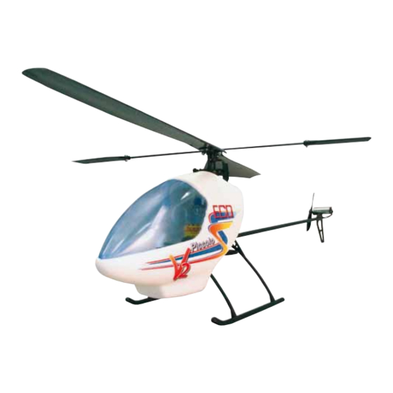
Sommaire des Matières pour iKarus ECOPiccoloV2

  • Page 1 ECO Piccolo V2 www.ikarus.net # 6041001 Deutsch: Bauanleitung English: Assembly instructions Français: Notice de montage 6049001-0410...
  • Page 2: Technische Daten

    11,1 V 800 mAh können Sie den fertig gebauten Piccolo mit dem für ca. 15 Min. Flugzeiten 8013006 Ladegerät für LiPo-Akku Bausatzkoffer leicht transportieren. IKARUS WÜNSCHT IHNEN VIEL SPASS BEIM Technische Daten: FLIEGEN DES PICCOLO Hauptrotor-Durchmesser: 500 mm Rumpflänge: 500 mm Fluggewicht: ca.
  • Page 3: Montage Chassis

    Montage Chassis Kleben Sie mit einem Tropfen CA-Kleber die 68245 Kabinenhalterung # 67380 mittig auf das Chassis # 67380 68245. Jetzt wird das Kufenlandegestell zusammen geclipst. Clipsen Sie nun die Kufen # 67465 in den vorderen und hinteren Kufenbügel # 67464 gemäß Zeichnung.
  • Page 4 Bevor Sie mit der Montage des Motors beginnen, sollten Sie den Motor einlaufen lassen. Dadurch können Sie die Lebensdauer und die Leistung deut- lich verbessern. Sofern Sie nicht das Original-Ikarus- Piccoboard verwenden, kann ein nicht eingelaufener Motor u.U., bedingt durch eine starke Funkenbil- dung, Störungen auf den Empfänger übertragen.
  • Page 5: Montage Rotorkopf

    Montage Rotorkopf Scharfkantig Die Kugelclips sind die wichtigsten Verbindungsele- mente für die Steuerung des Hubschraubers. Sie sol- len sich spielfrei, aber leichtgängig bewegen lassen. Gerundet Aufgrund von Fertigungstoleranzen kann dies werkseitig nicht zufriedenstellend voreingestellt wer- 67462 den. Deshalb sind die Clipse von uns so ausgelegt, dass sie eher etwas zu schwergängig sind.
  • Page 6 Montage Rotorkopf 67474 Stecken Sie die Paddelstange # 67474 durch den Rotorkopf, schieben dann die Anlenkhebel # 67368 67561 auf und fixieren sie mit den Schrauben M2x6/# 67561 so, dass die Stabistange mittig sitzt und die 67368 beiden Anlenkhebel in einer Ebene liegen. Achten Sie bitte darauf, dass sich die Stabistange leicht dre- 67582 hen lässt, aber ein kleinstmögliches Längsspiel hat.
  • Page 7: Montage Heckrotor

    Montage Heckrotor 67471 Pressen Sie jetzt den Heckpropeller # 67471 auf die Welle des Heckmotors # 67472. Achtung: der kegelförmige Ansatz der Propellernabe muß zum Motor zeigen, dabei ist zu beachten, dass zwischen Lagerschild vom Motor und dem Propeller Luft ist. Jetzt können Sie den Motor mit dem Propeller in das 68252 67472...
  • Page 8 RC- Einbau Schneiden Sie zunächst mit einem scharfen Messer oder einem Seitenschneider an beiden Servos die Befestigungslaschen ab. Montieren Sie die Gestän- 67387 67365 ge, indem Sie den Stahldraht zunächst mit dem L- förmigen Ende in den Clip # 67365 stecken und ihn dann um 90°...
  • Page 9 Endmontage Als nächstes verlegen Sie dann die Empfangsanten- ne, indem Sie diese zu einer Kufe führen und dort mit Klebeband so fixieren, dass noch ca 10 cm der Antenne frei hängen können. Jetzt wird noch der Flugakku mit einem Gummiring unter dem Vorbau befestigt.
  • Page 10 Das Fliegen Der ECO Piccolo V2 ist fertig aufgebaut, die Akkus mehr Gas nach rechts dreht (auch hier ist immer (auch vom Sender!) sind geladen und nun soll der die Nase gemeint), was sich mit der Trimmung Hubschrauber zeigen, was in ihm steckt. Dazu nicht ausgleichen lässt.
  • Page 11 Absturzrisiko minimiert, aber viele auch ganz allein. Eine echte Hilfe für Anfänger und Fortge- schrittene stellt ein sogenannter Flugsimulator wie der Aerofly Professional von IKARUS dar. Hier kann man die Feinmotorik der Steuerung lernen, ohne Sorge um sein Modell haben zu müssen. Ein...
  • Page 12: Mögliche Ursache

    Problem mögliche Ursache Folge Fehlerbehebung Piccoboard arbeitet Der Empfängerquarz am Piccoboard Der Empfänger kann die Signale vom Der Emfängerquarz, welcher nicht richtig, oder gar ist nicht eingesteckt. Sender nicht empfangen. normalerweise dem Sender nicht. beiliegt, muß wie abgebildet am Picccoboard eingesteckt werden.
  • Page 13 Explosions Zeichnung Piccolo V2 67561 68305 68240 67468 67474 67582 67471 67475 67396 67370 67472 67375 67561 68252 67375 67368 67473 67582 67561 67475 67367 67467 67400 67369 67477 67365 67392 68240 68215 67387 67366 67462 67385 67571 67476 68245 160556 67381 67380...
  • Page 14: Technical Data

    The finished Piccolo can be carried easily in the For assembly you will also need component case. A sharp knife IKARUS WISHES YOU LOTS OF FUN FLYING A small pair of fine-nosed pliers THE PICCOLO Symbols... We have used symbols to draw your attention to certain processes;...
  • Page 15: Chassis Assembly

    Chassis Assembly Now use one drop of CA glue to stick the canopy 68245 mount # 67380 to the middle of the main frame # 67380 68245. Now the skid landing gear is clipped toge- ther. Now clip the skids # 67465 into the front and rear skid brackets # 67464 as shown in the drawing.
  • Page 16 Before fitting the motor you should run the motor in. That will improve its life and power considerably. If you do not use the original Ikarus Piccoboard a motor that has not been run in could possibly cause interference with the receiver from large sparks.
  • Page 17 Rotorhead assembly sharp edged Smooth ball joint operation is vital. They should move easily and with no stiffness. rounded This cannot be set satisfactorily in the factory becau- se of production tolerances For that reason we de- 67462 sign the clips to err on the stiff side. As you will see, that can be adjusted quickly and easily.
  • Page 18 Rotorhead Assembly 67474 Push the flybar # 67474 through the rotorhead, then push on flybar control arm # 67368 and fix it with 67561 the M2x6 screws # 67561 so that the stabiliser rod sits in the centre and the two control arms are level. 67368 Ensure that the stabiliser rod can be turned easily but has as little longitudinal play as possible.
  • Page 19 Tail rotor fitting 67471 Now press the Tail rotor propellor # 67471 with the conical side inboard onto the shaft of the tail motor # 67472. Take care that there is a gap between the motor bearing shield and the propeller. Now attach the motor with the rotor into the tail housing # 67467.
  • Page 20 stallatio RC in First cut off the fixing lugs off both servos with a 67387 67365 sharp knife or an edge cutter. Fit the rod by first put- ting the L-shaped end of the steel wire in the ball link # 67365 and swivel it through 90°...
  • Page 21: Final Assembly

    Final assembly Now lay the receiver aerial by leading it to one of the skids and affix it so that about 10 cm of the aerial are hanging freely. Now the flight battery is fixed under the front end with a rubber band. Hang the ring sideways on the crossbar.
  • Page 22 Flying The ECO Piccolo V2 is completely built, the batteries the turning motion. In the situation just described (including the transmitter!) are charged and now the the tail mixture of the man rotor to the tail rotor is too helicopter has to show what it can do. For this we strong.
  • Page 23 Aerofly Profes- sional from IKARUS. Here you can learn the finer points of control without having to fear for your model. A modern flight simulator can simulate your model‘s flying properties and helps not only in the...
  • Page 24 Problem possible cause Consequence Remedy Piccoboard does not The receiver quartz on the Piccoboard The receiver cannot receive the The receiver quartz which is work properly or not is not plugged in. signals from the transmitter. normally with the transmitter at all.
  • Page 25 Exploded drawing of Piccolo V2 67561 68305 68240 67468 67474 67582 67471 67475 67396 67370 67472 67375 67561 68252 67375 67368 67473 67582 67561 67475 67367 67467 67400 67369 67477 67365 67392 68240 68215 67387 67366 67462 67385 67571 67476 68245 160556 67381...
  • Page 26: Données Techniques

    Pour le montage, vous aurez besoin en plus : monté dans le coffret prévu à cet effet. d’un couteau aiguisé d’une petite pince plate IKARUS vous souhaite de profiter pleinement de votre Piccolo. Symbole… Pour attirer votre attention sur certaines étapes, nous avons utilisé...
  • Page 27: Montage

    Montage 68245 Collez maintenant avec une goutte de colle CA 67380 le support de la cabine # 67380 sur le châssis # 68245. Puis clippez le train d‘atterrissage. Clippez ensuite les patins # 67465 dans les pattes de train avant et arrière # 67464 selon le schéma. Pressez ensuite le train d‘atterrissage dans l‘emplacement du châssis et clippez-le.
  • Page 28: Montage Du Bâti

    Dans la mesure où vous n’utilisez pas un Piccoboard origi- nal Ikarus, un moteur non utilisé peut entraîner, du fait d‘une forte formation d’étincelles, des interfé- rences sur le récepteur. La conséquence serait alors un tremblement provisoire des servos.
  • Page 29: Montage De La Tête Du Rotor

    Montage de la tête du rotor Non arrondi Les clips à boule sont les éléments de liaison les plus importants pour le pilotage de l‘hélicoptère. Ils ne doivent pas avoir de jeu mais bouger facilement. Arrondi En raison des tolérances de finition, ceci ne peut pas 67462 être préinstallé...
  • Page 30: Montage Tête Du Rotor

    Montage tête du rotor 67474 Enfoncez l‘axe des pales # 67474 à travers la tête du rotor, glissez alors le levier de direction # 67368 67561 et fixez-le à l‘aide des vis M2x6 / # 67561 de façon que l‘axe soit bien au milieu et que les deux leviers 67368 de direction soient au même niveau.
  • Page 31: Montage Rotor Arrière

    Montage Rotor arrière 67471 Pressez maintenant l‘hélice arrière # 67471 avec le côté rond sur l‘axe du moteur arrière # 67472. Veil- lez à ce qu‘il y ait assez d‘espace entre l‘étiquette du moteur et l‘hélice. Vous pouvez à présent visser le moteur et l‘hélice dans le boîtier # 67467 de 68252 l‘hélicoptère.
  • Page 32: Montage Radio

    Montage radio Coupez en premier lieu à l‘aide d‘un couteau aiguisé ou d‘une pince coupante les pattes de fixation des deux servos. Montez les tiges en insérant tout 67387 67365 d‘abord le fil en acier en forme de L au bout dans le clip # 67365 et tournez le à...
  • Page 33: Montage Final

    Montage final L‘étape suivante consiste à poser l‘antenne de récep- tion en la plaçant sur un patin et en la fixant avec du scotch afin qu‘env. 10 cm de l‘antenne soient suspen- dus librement. A présent, l‘accu de vol peut être fixé avec une rondelle en caoutchouc sous le prémonta- ge.
  • Page 34 Flying L’ECO Piccolo V2 est monté, les accus (de vous ne pourrez pas résoudre cela avec la com- l’émetteur également !) sont chargés – l’hélicoptère pensation. Cela signifie que le réglage arrière du doit à présent vous montrer ce qu’il a dans le ventre. Piccoboard n’est pas bon.
  • Page 35 Aussi bien pour les débutants que pour les pilotes confirmés, un simulateur de vol (comme l’Aerofly Professional d’IKARUS) apporte une aide précieu- se ; on y apprend la manipulation des moteurs de précision sans se soucier d’endommager son mo- dèle.
  • Page 36: Cause Possible

    Problème Cause possible Conséquence Réparation Le Piccoboard ne fonc- Le quartz du récepteur n’est pas bien Le récepteur ne peut pas recevoir les Le quartz du récepteur, qui tionne pas correcte- enfoncé dans le Piccoboard. signaux de l’émetteur. est normalement livré avec ment ou pas du tout.
  • Page 37 Schéma éclaté Piccolo V2 67561 68305 68240 67468 67474 67582 67471 67475 67396 67370 67472 67375 67561 68252 67375 67368 67473 67582 67561 67475 67367 67467 67400 67369 67477 67365 67392 68240 68215 67387 67366 67462 67385 67571 67476 68245 160556 67381 67380...
  • Page 38 Notizen: Notes: Notice:...
  • Page 39: Warranty Terms

    Conditions de garantie Nous offrons une garantie de 24 mois pour le produit IKARUS. La date du ticket de caisse est la date du début de la garantie. D’éventuelles réparations ne prolongent pas cette durée. Si pendant cette période, des défauts matériels ou de fabrication ainsi que des ratés au niveau fonctionnel surviennent, nous les réparerons.

Table des Matières