Publicité
Les langues disponibles
Les langues disponibles
Liens rapides
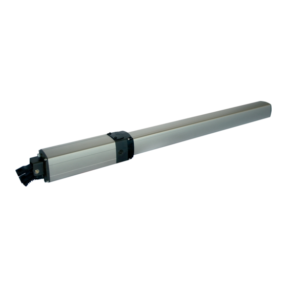
IDRO C 27
Scarica questo manuale sul tuo cellulare
Téléchargez ce manuel sur votre mobile
Download this manual on your mobile
Laden Sie dieses Handbuch auf Ihr Handy herunter
Descarga este manual en tu móvil
Operatore
Operateur
Operator
Torantrieb
IDRO C 27/R
IDRO C 27/1B
IDRO C 27/2B
KIT IDRO C 27/1B
Die korrekte Bedienung des Bedieners ist nur gewährleistet, wenn er von einem RIB-Bedienpanel verwaltet wird
con / avec / with / mit
Alimentazione
Alimentation
Power Supply
Stromspannung
230V 50Hz
Il corretto funzionamento dell'operatore è garantito solo se viene gestito da un quadro di comando RIB
Le bon fonctionnement de l'opérateur n'est garanti que s'il est géré par un panneau de contrôle RIB
The correct operation of the operator is guaranteed only if it is managed by a RIB control panel
El funcionamiento correcto del operador solo está garantizado si está gestionado por un panel de control RIB
ITALIANO pag. 04 / FRANÇAIS pag. 17 / ENGLISH page 30 / DEUTSCH pag. 43
Lunghezza max. anta
Peso max cancello
Longueur maxi du battant
Poids maxi portail
Max gate weight
Max. leaf length
Max Torgewicht
Max. Torflügelweite
250 kg
B2-CRX
Manuali online interattivi
Manuels interactifs en ligne
Interactive online manuals
Interaktive Online-Handbücher
Manuales interactivos en línea.
Vedere pagina 18
Voir page 33
See page 48
Siehe Seite 63
Ver página 78
Codice
Code
Code
Kode
AA10882
AA10884
2 m
AA10883
AD00756
Publicité

Manuels Connexes pour RIB IDRO C 27


Sommaire des Matières pour RIB IDRO C 27
- Page 1 Le bon fonctionnement de l’opérateur n’est garanti que s’il est géré par un panneau de contrôle RIB The correct operation of the operator is guaranteed only if it is managed by a RIB control panel Die korrekte Bedienung des Bedieners ist nur gewährleistet, wenn er von einem RIB-Bedienpanel verwaltet wird El funcionamiento correcto del operador solo está...
- Page 2 2° - En ce qui concerne la section et le type des câbles, RIB conseille d’utiliser un câble de 2° - Per la sezione ed il tipo dei cavi la RIB consiglia di utilizzare un cavo di tipo H05RN-F con type H05RN-F ayant une section minumum de 1,5 mm 2 et de toute façon, s’en tenir à...
- Page 3 Kontaktöffnung von 3 mm), der ein von den internationalen Normen 2° - For the section and the type of the cables RIB advices to use a cable of H05RN-F type anerkanntes Konformitätszeichen besitzt. Solch ein Geraet muss vor Vandalismus with 1,5 sqmm minimum section and, however, to keep to the IEC 364 and installation geschuetzt werden (z.B.mit einen Schluesselkatsten in einem Panzergehaeuse).
- Page 4 D: Coste e/o altri dispositivi supplementari per ridurre la probabilità di contatto con la porta. E: Dispositivi installati in modo tale che una persona non possa essere toccata dalla porta. CARATTERISTICHE IDRO C 27/1B Tensione di alimentazione monofase 230 V±10% 50/60 Hz...
- Page 5 ALLACCIAMENTO ELETTRICO DEL SISTEMA - Per eseguire gli allacciamenti elettrici attenersi scrupolosamente alle istruzioni allegate ai Attenzione singoli componenti seguendo lo schema riportato in B1. • Ogni attuatore è fornito con condensatore di spunto compreso nell’imballo. Al momento dell’installazione, collegare il condensatore all’interno dell’apparecchiatura elettrica in base Attenzione allo schema di collegamento della stessa.
- Page 6 (C4) . Le dimensioni della piastra di rinforzo vanno proporzionate alle dimensioni della colonna. Attenzione • Qualora le dimensioni della colonna lo consentano, utilizzare la piastra standard RIB in dotazione. 3.1.3 Attuatore fissato su pilastri in muratura Se i pilastri di sostegno delle ante del cancello sono in muratura, occorre predisporre su ciascuno una piastra metallica dotata di ancoraggi sulla quale saldare l’attacco posteriore...
- Page 7 Cautela • Le dimensioni delle piastre, escluso quelle standard RIB, vanno proporzionate alle dimensioni delle colonne. • Se si utilizza la piastra di tipo A e si rendesse necessario posizionarla in asse con l’attuatore, occorre modificare le zanche nel modo indicato in fig. C7.
- Page 8 FISSAGGIO ATTACCO POSTERIORE DELL’ATTUATORE Posizionare l’attacco posteriore in base alle quote stabilite precedentemente e fissarlo alla piastra di ancoraggio con due punti di saldatura (C11). Controllare con una livella l’allineamento longitudinale e trasversale (C12) dell’attacco. Completare la saldatura e rimuovere le scorie con una spazzola metallica. Attenzione •...
- Page 9 C16b POSIZIONAMENTO ATTACCO ANTERIORE Spalmare di grasso il gambo filettato dello snodo sferico (C16 pos.1), inserire nell’asta dell’attuattore lo snodo sferico corredato di dado (C16 pos.2) e, avvitandolo per circa metà filetto, inserire nello snodo sferico il perno (C16 pos.4) dell’attacco anteriore senza bloccarlo con il relativo seeger.
- Page 10 3.5.2 Controlli sulla movimentazione Attenzione • A montaggio effettuato movimentare manualmente le ante, dopo avere neutralizzato (se presente negli attuatori) il blocco idraulico tramite l’apposita chiave ruotando la stessa di 180° in senso antiorario, per controllare la loro scorrevolezza; eseguire l’operazione molto lentamente per evitare che gli attuatori aspirino aria e di conseguenza si renda necessario lo spurgo degli stessi.
- Page 11 Inserire se necessario, nel cavo di alimentazione (E5 pos. 5) una guaina di protezione. Cautela É normale la fuoriuscita di una goccia di olio idraulico dal condotto aperto dalla eliminazione della vite (E5 pos. 4). Informazioni Al termine dell’installazione è necessario corredare il cancello con l’apposito cartello di segnalazione.
- Page 12 Durante il movimento l'attuatore Insufficiente quantità di olio all'interno del Verificare la presenza di eventuali perdite di olio e, funziona a scatti se presenti, contattare il Centro riparazioni RIB. cilindro. Gli attacchi anteriori e posteriori dell'attuatore Ripristinare o rinforzare gli attacchi.
- Page 13 COLLEGAMENTI ELETTRICI cod. AC08074 700 W MAX COMUNE FINECORSA APERTURA M1 FINECORSA CHIUSURA M1 FINECORSA APERTURA M2 FINECORSA CHIUSURA M2 COMUNE STOP FOTOCELLULA 1 FOTOCELLULA 2 COSTA 1 COSTA 2 COMUNE OROLOGIO PEDONALE ANTENNA 433 MHz COMANDO SINGOLO CHIUDE SCHERMATURA APRE CAVO D’ANTENNA...
- Page 14 A- CONNESSIONI Alimentazione 230 Vac 50/60 Hz N -L (120V/60Hz a richiesta) COLLEGAMENTO COMUNE MOTORE 1 COLLEGAMENTO INVERTITORI E CONDENSATORE V1 - W1 MOTORE 1 COLLEGAMENTO COMUNE MOTORE 2 COLLEGAMENTO INVERTITORI E CONDENSATORE V2 - W2 MOTORE 2 Lampeggiatore (max 40 W ) Antenna radio 433 MHz Connettore per radio ricevitore ad innesto con RADIO...
- Page 15 IDRO C 2/27B AA10882 o per eventuali controlli successivi. IDRO C 27/R AA10883 1 - Posizionare il cancello a metà corsa utilizzando lo sblocco manuale. 2 - Mettere il DIP 1 su ON => il led rosso DL1 inizia a lampeggiare.
- Page 16 R-AUX funziona normalmente come luce di cortesia per 3 minuti. DIP 13 su ON (di fabbrica): si possono memorizzare telecomandi a codice fisso SUN: Tramite App RIB GATE è possibile configurare il funzionamento di questo relé a piacere. SUN 2CH bicanale - tasti blu e led bianco cod.
- Page 17 PULSANTE DI COMANDO PASSO-PASSO (COM A+/START) del moto inverso dopo un secondo anche se le stesse restano impegnate). DIP 6 ON => Esegue un comando ciclico dei comandi apre-stop-chiude-stop-apre ecc. ATTENZIONE: Se il led del ricevitore rimane acceso è possibile che siano presenti dei disturbi DIP 6 OFF =>...
- Page 18 Ha il compito di segnalare l’intervento delle sicurezze, lo stato degli allarmi e lo stato di Durante il funzionamento a uomo presente, con DIP1 in ON, verificare che durante l’apertura di memorizzazione e cancellazione codici radio. M1 e M2 si accendano i led verdi DL2 e DL4 e che durante la chiusura di M1 e M2 si accendano i led rossi DL3 e DL5.
- Page 19 Costa con resistenza 8,2 KΩ. Togliere la resistenza o configurare l’ingresso EDGE tramite App Il buzzer emette 2 toni prolungati e il cancello non si muove RIB GATE Il telecomando non funziona. Led DL12 acceso rosso fisso Mancanza modulo radio nel connettore J5 o modulo radio guasto.
- Page 20 OPTIONAL - Per i collegamenti ed i dati tecnici degli accessori attenersi ai relativi libretti di istruzione. MODULO RADIO 433MHz TELECOMANDO SUN cod. ACG8069 SUN 2CH cod. ACG6052 SUN 4CH cod. ACG6054 SUN CLONE 2CH cod. ACG6056 SUN CLONE 4CH cod.
- Page 21 Annex A D: Coste e/o altri dispositivi supplementari per ridurre la probabilità di contatto con la porta. E: Dispositivi installati in modo tale che una persona non possa essere toccata dalla porta. IDRO C 27/1B CARACTÉRISTIQUES Tension d’alimentation monophasée 230 V ±10% 50/60 Hz...
- Page 22 BRANCHEMENT ELECTRIQUE DU SYSTEME - Pour effectuer les branchements électriques, respecter rigoureusement les instructions Attention fournies avec les composants en suivant le schéma indiqué en B1. • Chaque automatisme est fourni complet avec condensateur de courant. Lors de l’installation, relier le condensateur à l’intérieur de l’équipement électrique en suivant le schéma fourni. Attention - Une fois les branchements électriques effectués, vérifier la force de poussée à...
- Page 23 Les dimensions de la plaque de renforcement doivent être proportionnées aux dimensions du pilier. Attention • Si les dimensions du pilier sont adaptées, utiliser la plaque standard RIB fournie. 3.1.2 Automatisme fixé sur des piliers en bois Si les piliers soutenant les vantaux du portail sont en bois, il faut appliquer une plaque de renforcement d’un coin à...
- Page 24 Prudence • Les dimensions des plaques, à l’exception de celles standard RIB, doivent être proportionnées aux dimensions des piliers. • Lorsque l’on utilise la plaque du type A et qu’elle doit être alignée à l’automatisme, il est nécessaire de modifier les agrafes comme indiqué à la fig.
- Page 25 FIXATION DE LA PATTE ARRIERE DE L’AUTOMATISME Placer la patte arrière aux cotes définies avant et la fixer à la plaque d’ancrage avec deux points de soudure (C11). A l’aide d’un niveau à bulle d’air, vérifier l’alignement longitudinal et transversal (C12) de la patte de fixation.
- Page 26 MISE EN PLACE DE LA FIXATION AVANT C16b Etalez de la graisse sur la tige filetée de la rotule (C16 pos. 1), introduisez dans la tige de l’opérateur la rotule avec l’écrou (C16 pos. 2) et vissez-le jusqu’à la moitié du filet. Introduisez dans la rotule le pivot (C16 pos.
- Page 27 3.5.2 Contrôle du déplacement Attention • Une fois le montage effectué, déplacer manuellement les vantaux pour en vérifier le glissement, après avoir désactivé (si présent) le blocage hydraulique en tournant la clé spéciale de 180° dans le sens anti-horaire. Effectuer cette opération très lentement afin d’éviter que les automatismes aspirent de l’air, ce qui rendrait nécessaire leur purge.
- Page 28 Si nécessaire, protéger le câble d’alimentation (E5 pos. 5) avec une gaine de protection. Prudence Il est normal qu’une goutte d’huile hydraulique sorte de l’ouverture créée par l’élimination de la vis (E5 pos. 4). Informations A la fin de l’installation, appliquer sur le portail la pancarte de signalisation prévue. 3.5.5 Purge de l’air Attention...
- Page 29 Vérifiez s'il y a des pertes d'huile; dans ce cas, fonctionne à-coup. Quantité d'huile insuffisante dans le piston. contactez le Centre de Réparation RIB. Les fixations avant et arrière de l'opérateur ne Réparez ou renforcez les fixations. sont pas fixés d'une façon correcte.
- Page 30 BRANCHEMENTS ÉLECTRIQUES cod. AC08074 700 W MAX COMMUN FIN OUVERTURE M1 FIN FERMETURE M1 FIN OUVERTURE M2 FIN FERMETURE M2 COMMUN STOP PHOTOCELLULES 1 PHOTOCELLULES 2 CORDON 1 CORDON 2 COMMUN HORLOGE PIETON ANTENNE 433 MHz COMMANDE UNIQUE FERMETURE ENVELOPPE ANTENNE OUVERTURE COMMUN...
- Page 31 CONNEXION COMMUN MOTEUR 2 CONNEXION INVERSEURS ET CONDENSATEUR MOTEUR V2 - W2 Connexion clignotant 230V (max 40 W ) Antenne radio 433 MHz Connecteur pour radio récepteur RIB à RADIO enclenchement avec alimentation à 24Vdc RADIO Connecteur pour module radio ACG8069 réservé...
- Page 32 IDRO C 2/27B AA10882 OPEN Commande ouverture (vert) IDRO C 27/R AA10883 C - CONTRÔLE DU SENS DE ROTATION DES MOTEURS TRIMMER TORQUE - RÉGULATEUR ÉLECTRONIQUE DE LA FORCE Ce contrôle a la tâche d’aider l’installateur durant la mise en œuvre de l’installation ou pour les La régulation de la force est effectuée en faisant tourner le Trimmer TORQUE qui sert à...
- Page 33 DIP 13 ON (par usine): Vous pouvez mémoriser les télécommandes avec le code fixe SUN: Grâce à l’application RIB GATE, il est possible de configurer le fonctionnement de ce relais à SUN 2CH deux canaux - touches bleues et LED blanche cod.
- Page 34 nouveaux codes comme dans la procédure décrite ci-dessus. le déblocage manuel. 4 - Repositionner DIP 1, 2, 3 sur OFF. COUP D’ENCLENCHEMENT DE LA SERRURE ELECTRIQUE SIGNALISATION MEMOIRE SATUREE CODES RADIO RESERVES A L’OUVERTURE PIETONNE Mettre le DIP 11 sur ON pour activer le coup d’enclenchement de la serrure électrique en phase La signalisation ne s’obtient que lorsque le portail est stationnaire.
- Page 35 A la restauration du contact de sécurité, l’opération est restaurée après une seconde, et donc aussi la télécommande et la fermeture automatique sont de travail. - Toutes les entrées doivent être utilisées comme des contacts propres parce que l’alimentation Note 1: Au cours de cette opération dans le cas de panne de les barres palpeuses (ou est générée internement (tension sécuritaire) à...
- Page 36 Barre palpeuse avec résistance 8,2 KΩ. Retirez la résistance ou configurez l'entrée EDGE avec Le buzzer émet 2 longs sons et le portail ne fonctionne pas l'application RIB GATE La télécommande ne fonctionne pas. Led DL12 allumé en rouge Absence de module radio dans le connecteur J5 ou module radio défectueux.
- Page 37 OPTIONS Pour les branchements et les données techniques des accessoires, se conformer aux livrets d’instruction correspondants. EMETTEUR RADIO SUN MODULE RADIO 433MHz SUN 2CH cod. ACG6052 SUN 4CH cod. ACG6054 cod. ACG8069 SUN CLONE 2CH cod. ACG6056 SUN CLONE 4CH cod.
- Page 38 D: Safety strips and/or other additional devices to reduce the probability of contact with the door. E: Devices installed in such a way that a person can not be touched by the door. CARACTERISTIQUES IDRO C 27/1B Single-phase system voltage 230 V±10% 50/60Hz Motor capacity with load...
- Page 39 SYSTEM ELECTRICAL CONNECTION - When making the electrical connections,carefully follow the instructions for each of Warning the components, referring to the wiring diagram B1. • Every operator comes complete with a pickup capacitor. During installation, connect the capacitor to the electrical equipment according to the wiring diagram supplied. Warning - After making the electrical connections, check the thrust force at the end of the gate leaf;...
- Page 40 The size of the reinforcing plate must be in proportion to the size of the column. Warning • If the size of the column allows for it, use the RIB standard plate provided. 3.1.2 Operator fixed on wooden posts If the gate supporting posts are made of wood, it is necessary to fit a reinforcing plate on the column, covering it from edge to edge, in the rear mounting welding zone.
- Page 41 Caution • The size of the plates, apart from standard RIB plates, must be proportioned to the size of the columns. • If the A-type plate is used and has to be positioned in line with the operator axis, the hook fittings must be modified as shown in fig.
- Page 42 FIXING THE REAR OPERATOR MOUNTING Position the rear mounting at the height previously measured and weld it on the anchorage plate with two weld points (C11). Check the lengthwise and crosswise alignment of the mounting (C12) with a water level. Complete the welding and clean away the residues with a wire brush.
- Page 43 POSITIONING THE FRONT MOUNTING C16b Spread grease on the threaded stem of the ball joint (C16 pos. 1), fit the ball joint, along with its nut (C16 pos. 2) and to the operator arm, screwing on to about halfway along the thread. Insert the pin (C16 pos.
- Page 44 3.5.2 Checking the motion Warning • When the mounting is completed, neutralize the hydraulic lock (if present in the operators) by turning the correct key through 180° counter-clockwise, and move the gate-leaves manually to check on the smoothness of the movement; this should be done very slowly, otherwise the operators will take in air and, consequently, will have to be bled.
- Page 45 Fit the protective sheath to the power supply cable (E5 pos. 5) if necessary. Caution One drop of hydraulic oil coming out of the duct created by the screw elimination (E5 pos. 4) is normal. Information After installation, an appropriate warning sign must be attached to the gate 3.5.5 Bleeding Warning...
- Page 46 During the motion, the operator jerks. Check for oil leaks; if any, address to an Oil in the cylinder not enough. RIB Repair Centre. The front and rear operator mountings Repair or strengthen the mountings. move or have been fitted incorrectly.
- Page 47 cod. AC08074 ELECTRIC CONNECTIONS 700 W MAX COMMON LIMIT SWITCH OPEN M1 LIMIT SWITCH CLOSE M1 LIMIT SWITCH OPEN M2 LIMIT SWITCH CLOSE M2 COMMON STOP PHOTOCELL 1 PHOTOCELL 2 EDGE 1 EDGE 2 COMMON TIMER PEDESTRIAN ANTENNA 433 MHz SINGLE COMMAND CLOSE ANTENNA...
- Page 48 V2 - W2 MOTOR 2 PHASES AND CAPACITOR CONNECTIONS Flashing light (max 40 W ) Radio Antenna 433MHz RADIO Connector for radio receiver RIB, 24 Vdc supply RADIO Connector for radio module ACG8069 reserved SERIAL COM/SYNC Connector for serial connection...
- Page 49 3 - Press the PROG button and hold it - When GREEN LEDS DL2 and DL4 are on, the gate leaves are IDRO C 2/27B AA10882 opening (with a phase shift of 2 s). Check the leaves swinging and the opening mechanical IDRO C 27/R AA10883 stopper position (movement is now performed in “man present” mode, open-close-open- etc.).
- Page 50 R-AUX normally works as a courtesy light for 3 minutes. 5 - Press the pedestrian pushbutton (COM A+/PED.), M1 closes. Through the RIB GATE app it is possible to configure the operation of this relay as desired. 6 - Turn DIP 1 to OFF position.
- Page 51 activated when gate is open, the gate closes. If activated while closing, the gate EDGE ALARM reopens. Flasher and buzzer are activated with 2 tones every 5 s for one minute. PEDESTRIAN OPEN BUTTON (COM A+/PED.) STOP BUTTON (COM A+/STOP) Partial opening and closing control.
- Page 52 TECHNICAL SPECIFICATIONS - Temperature range -10 ÷ + 55°C - Humidity < 95% without condensation - Power supply voltage 230 V o 120 V~ ±10% - Frequency 50/60 Hz - Maximum absorption 45 mA - Power supply microinterruptions 100 ms - Maximum power SIGNAL output 24 Vdc 3W - Maximum load of blinker output...
- Page 53 The electric lock does not work. Check the cable. Safety edge with 8,2 KΩ resistor. Remove the resistor or configure the EDGE input via the RIB The buzzer emits 2 long tones and the gate does not move GATE app The remote control does not work.
- Page 54 ACCESSORIES For the connections and the technical data of the optional equipments follow the relevant handbooks. RADIO MODULE 433MHz RADIO TRANSMITTER SUN SUN 2CH cod. ACG6052 SUN 4CH cod. ACG6054 code ACG8069 SUN CLONE 2CH cod. ACG6056 SUN CLONE 4CH cod.
- Page 55 D: Kontaktleiste und /oder andere zusätzliche Geräte, um die Wahrscheinlichkeit eines Kontakts mit der Tür zu verringern E: Geräte, die so installiert sind, dass eine Person nicht von der Tür berührt werden kann. MERKMALE IDRO C 27/1B Einphasen-Netzstrom 230 V±10% 50/60 Hz Motorleistung...
- Page 56 ELEKTROANSCHLUSS DES SYSTEMS - Bei Durchführen der Kabelanschlüsse sind die mitgelieferten Anleitungen zu den einzelnen Achtung Komponenten und das Schaltschema unter D1 sorgfältig zu befolgen. • Alle Antriebe werden zusammen mit Anlasskondensator geliefert. Während der Installation den Kondensator gemäß dem mitgelieferten Anschlußplan im Inneren des Elektrokastens Achtung anschließen.
- Page 57 Pfostens für die Anschweißung des hinteren Drehpunkts des Antriebs angebracht werden. Die Platte muss mit Befestigungsschrauben (C4) am Pfosten festgemacht werden. Die Verstärkungsplatte soll größenmäßig proportionell zum Pfosten ausgelegt sein. Achtung • Wenn es die Abmessungen des Pfostens zulassen, die mitgelieferte Standardplatte von RIB verwenden. 3.1.3 An gemauerten Pfeilern befestigter Antrieb Wenn die Trägerpfeiler der Torflügel gemauert sind, muss auf jedem eine Metallplatte mit Verankerung...
- Page 58 Vorsicht • Die Abmessungen der Platten (ausgenommen standardmäßige RIB-Platten) müssen proportionell zur Säulengröße ausgelegt sein. • Verwendet man eine Platte vom Typ A und sofern diese mit dem Antrieb fluchten soll, so sind die Krampen gemäß Abbildung C7 abzuändern. Die Fläche von eventuellen Zement- oder Sandrückständen reinigen.
- Page 59 BEFESTIGUNG DES HINTEREN DREHPUNKTS DES ANTRIEBS Hinteren Drehpunkt nach den vorher festgelegten Maßen positionieren. Drehpunkt an Ankerplatte mit 2 Schweißnähten (C11) festmachen. Mit einer Libelle Längs- und Querfluchtung (C12) des Drehpunkts überprüfen. Den Schweißvorgang beenden und Schlacken mit einer Metallbürsten gründlich entfernen. Achtung •...
- Page 60 POSITIONIERUNG DES VORDEREN DREHPUNKTS C16b Gewindeschaft des Kugelgelenks (C16 Pos. 1) mit Fett abschmieren. Das mit der Mutter (C16 Pos. 2) bestückte Kugelgelenk in die Antriebsstange einführen. Kugelgelenk um etwa eine halbe Gewindedrehung zuschrauben. Bolzen (C16 Pos. 4) des vorderen Drehpunkts ins Kugelgelenk einsetzen, ohne ihn jedoch mit dem entsprechenden Seegerring zu verriegeln.
- Page 61 3.5.2 Kontrolle der Bewegung Achtung • Nach Beenden der Montage die Flügel von Hand bewegen, nachdem die hydraulische Sperrung (falls die Antriebe damit ausgerüstet sind) mit dem zugehörigen Schlüssel abgeschaltet wurde. Den Schlüssel um 180° gegen den Uhrzeigersinn drehen, um die Gleitfähigkeit der Flügel zu testen.
- Page 62 Soweit erforderlich, Stromkabel (E5 Pos. 5) mit Schutzmantel versehen. Vorsicht Der Austritt eines Tropfens Hydrauliköls aus der Öffnung nach der Abnahme der Schraube ist normal (E5 Pos. 4). Informationen Nach Beenden der Installation muß das Tor mit dem entsprechenden Warnzeichen versehen werden.
- Page 63 Ein paarmal öffnen und schlie en. Dann den vorderen Drehpunkt wieder anschließen. Der Antrieb führt ruckweise Auf Ölverluste kontrollieren; falls vorhanden, sich Bewegungen aus. Ölmenge im Zylinder ungenügend. an den RIB-Kundendienst wenden. Vorderer und hinterer Drehpunkt geben nach Drehpunkt reparieren oder verstärken. oder sind ungenügend befestigt.
- Page 64 cod. AC08074 ELEKTROANSCHLÜSSE 700 W MAX GEMEINSAMER ERDUNGSKONTAKT ENSCHALTER ÖFFNEN M1 ENSCHALTER SCHLIESSEN M1 ENSCHALTER ÖFFNEN M2 ENSCHALTER SCHLIESSEN M2 GEMEINSAMER ERDUNGSKONTAKT STOP FOTOZELLEN 1 FOTOZELLEN 2 KONTAKTLEISTE 1 KONTAKTLEISTE 2 GEMEINSAMER ERDUNGSKONTAKT ZEITGESTUERTE ÖFFNUNG FUSSGÄNGER ANTENNE 433 MHz EINZELIMPULS SCHLIEßEN ANTENNE ZOPFFLECHTEN...
- Page 65 ANSCHLUSS WENDEGETRIEBE UND KONDENSATOR MOTOR 1 GEMEINSCHAFTSANSCHLUSS MOTOR 2 V2 - W2 ANSCHLUSS WENDEGETRIEBE UND KONDENSATOR MOTOR 2 Blinker (max. 40 W) Radioantenne 433 MHz Verbinder für Radioempfänger RIB Steckverbindung mit RADIO Speisung zu 24Vdc RADIO Verbinder für Radio-Modul ACG8069 reserviert SERIAL COM/SYNC Anschluss für serielle Verbindung...
- Page 66 OPEN Befehl Öffnung (NO) (Grün) IDRO C 2/27B AA10882 C - KONTROLLE DER MOTORENDREHRICHTUNG IDRO C 27/R AA10883 Diese Kontrolle soll den Installateur während der Inbetriebsetzung der Anlage oder bei den eventuellen anschließenden Kontrollen unterstützen. TRIMMER TORQUE - ELEKTRONISCHER KRAFTREGLER 1 - Das Tor mit der manuellen Entblockungsvorrichtung auf Halblaufsposition einstellen.
- Page 67 SUN-PRO 4CH 4-Kanal - rote Tasten und weiße LED Kode ACG6214 Über die RIB GATE-App kann der Betrieb dieses Relais wie gewünscht konfiguriert werden. Die Programmierung kann nur bei stehendem Tor erfolgen. DIP 13 ON (Voreinstellung) : Sie können Sender mit festem Code SUN speichern: 1 - Stellen Sie DIP 1 auf ON, DIP 2 auf ON und DIP 3 auf ON.
- Page 68 DIP 4 OFF => Kommt bei geschlossenem Tor ein Hindernis in den Wirkkreis der Fotozelle, so STEUERTASTE FÜR SCHRITTWEISEN BETRIEB (COM A+/START) öffnet sich das Tor nicht. Während der Funktion des Tors wirken die Fotozellen DIP 6 ON => führt einen Befehl der Steuerreihe Öffnen-Stopp-Schließen-Stopp-Öffnen usw. sowohl bei der Öffnung (mit Wiederherstellung der Öffnungsbewegung nach aus.
- Page 69 und mit der Visuell-Sicherheit der Autmatismum-Bewegung gemacht wird sein. So bald ausgeführt werden, damit die doppelte oder verstärkte Isolierung gegenüber den Teilen mit wie möglich, muss der Fehler Schutz, für den ordnungsgemäßen Betrieb, wiederhergestellt gefährlicher Spannung garantiert werden kann. werden sein. - Alle Eingänge werden von einem programmierten integrierten Schaltkreis, der bei jedem Start eines Laufes eine Selbstkontrolle vornimmt, verwaltet.
- Page 70 Kontaktleiste mit 8,2 KΩ Widerstand. Entfernen Sie den Widerstand oder konfigurieren Sie den Der Summer gibt 2 lange Töne ab und das Tor bewegt sich nicht. EDGE-Eingang über die RIB GATE-App Die Fernbedienung funktioniert nicht. LED DL12 leuchtet rot Fehlendes.
- Page 71 OPTIONEN Für die Anschlüsse und die technischen Daten der Zubehöre verweisen wir auf die entsprechenden Betriebsanleitungen. FERNSENDER SUN RADIO-MODUL 433MHz SUN 2CH Kode ACG6052 SUN 4CH Kode ACG6054 Kode ACG8069 SUN CLONE 2CH Kode ACG6056 SUN CLONE 4CH Kode ACG6058 SUN-PRO 2CH Kode ACG6210 SUN-PRO 4CH...
- Page 72 COLLEGAMENTI FOTOCELLULE - CONNEXIONS PHOTOCELLULE - PHOTOCELLS CONNECTIONS FOTOZELLEN VERBINDUNGEN 4 fotocellule FIT SLIM / FIT SYNCRO con autotest e sincronizzatore del segnale infrarosso 2 fotocellule FIT SLIM, FIT SYNCRO con autotest 4 photocellules FIT SLIM / FIT SYNCRO avec autotest et synchroniseur de signal infrarouge 2 photocellules FIT SLIM, FIT SYNCRO avec autotest 4 FIT SLIM / FIT SYNCRO photocells with self-test and infrared signal synchronizer 2 photocells FIT SLIM, FIT SYNCRO with self-test...
- Page 73 COLLEGAMENTI FOTOCELLULE - CONNEXIONS PHOTOCELLULE - PHOTOCELLS CONNECTIONS FOTOZELLEN VERBINDUNGEN 4 fotocellule NOVA sincronizzate con autotest 4 photocellules NOVA synchronisées avec autotest 4 NOVA photocells synchronized with self-test 4 NOVA Photozellen synchronisiert mit Selbstkontrolle COM/PHOT A+ TEST ATTENZIONE: Se si attiva la funzione AUTOTEST e si collega una sola fotocellula, si WARNING: If the AUTOTEST feature is enabled and only one photocell is connected, deve fare un ponticello tra i morsetti PHOT 1 e PHOT 2.
- Page 75 IDRO C 27/1B Cod. Descrizione n° IDA1028 DISTRIBUTORE IDA1023 PROFILO COPRI-MOTORE IDA1012 CONF. ATTACCO POSTERIORE IDA1013/1 CONF. ATTACCO ANTERIORE IDA1022 PROFILO COPRI-STELO CEL1385 CONDENSATORE 6 µF IDA1029 FLANGIA ANTERIORE IDA1011 TAPPO FRONTALE IDA1024 TIRANTE FLANGIA ANTERIORE IDA1034 GUARN. TENUTA CANNA...
- Page 76 R.I.B. S.r.l. - Via Matteotti, 162 - 25014 Castenedolo - Brescia - Italy Tel. ++39.030.2135811 - www.ribind.it - ribind@ribind.it Apparecchio modello : Oggetto della dichiarazione : IDRO C 27 Modèle d'appareil : Objet de la déclaration : Apparatus model :...