Télécharger Imprimer la page

Publicité

Les langues disponibles

Les langues disponibles

Liens rapides

Einbau- und Bedienungsanleitung
Installation & Operating Instructions
All manuals and user guides at all-guides.com
MONO, 2- AND 4-CHANNEL
POWER AMPLIFIERS

Publicité

loading

Sommaire des Matières pour AXTON C109

  • Page 1 All manuals and user guides at all-guides.com MONO, 2- AND 4-CHANNEL POWER AMPLIFIERS Einbau- und Bedienungsanleitung Installation & Operating Instructions...
  • Page 2 Allgemeine Merkmale ......4 Anschlüße & Bedienungselemente C109 ..5/6 Anschlüße &...
  • Page 3 General Features ......24 Connections & Controls C109 ....25/26 Connections et réglages C109.
  • Page 4 Einleitung ALLGEMEINE MERKMALE AXTON C109/C209/C409/C509 Vielen Dank für das Vertrauen, das Sie uns mit dem Kauf dieses AXTON- Qualitätsprodukts entgegengebracht haben. Ob im Auto, Wohnmobil oder auf einem Boot, die AXTON Car Audio ∑ PWM MOSFET Schaltnetzteile mit hohem Wirkungsgrad Verstärker wurden speziell für den Einsatz in mobilen Sound systemen...
  • Page 5 All manuals and user guides at all-guides.com Anschlüße & Bedienungselemente Frontseite AXTON C109 Anschlüße & Bedienungselemente Rückseite AXTON C109...
  • Page 6 All manuals and user guides at all-guides.com ANSCHLÜSSE & BEDIENUNGSELEMENTE C109 INPUT L+R REMOTE/REM Cinch-Eingangsbuchsen links und rechts zum Anschluß an die NF / Anschluß-Klemme für die automatische Ein-bzw. Ausschaltung des Pre-Out Signal-Ausgänge des Steuergerätes. Verstärkers über den 'Amp'- oder 'Antenna-Remote' Anschluß Ihres Steuergerätes.
  • Page 7 All manuals and user guides at all-guides.com Anschlüße & Bedienungselemente Frontseite AXTON C209 und C409 Anschlüße & Bedienungselemente Rückseite AXTON C C209 und C409...
  • Page 8 All manuals and user guides at all-guides.com ANSCHLÜSSE & BEDIENUNGSELEMENTE C209/C409 INPUT L+R +12 V Cinch-Eingangsbuchsen links und rechts zum Anschluß an Anschluß-Klemme für die direkte Verbindung zum positiven die NF / Pre-Out Signal-Ausgänge des Steuergerätes. Batterie-Pol des Kfz. INPUT GAIN REMOTE / REM Eingangsempfindlichkeitsregler zur Anpassung des Anschluß-Klemme für die automatische Ein-bzw.
  • Page 9 All manuals and user guides at all-guides.com Anschlüße & Bedienungselemente Frontseite AXTON C509 Anschlüße & Bedienungselemente Rückseite AXTON C509...
  • Page 10 All manuals and user guides at all-guides.com HIGHPASS FREQ. (3CH/4CH) Regler zum Einstellen der ANSCHLÜSSE & BEDIENUNGSELEMENTE C509 gewünschten Highpass (HPF) Übergangs- bzw. Trennfrequenz für die Kanäle 3+4 an der integrierten elektronischen Frequenzweiche zwischen INPUT L+R (1CH/ 2CH) Cinch-Eingangsbuchsen links und 40 Hz und 240 Hz.
  • Page 11 Luft ungehindert an den Kühlrippen vorbeiziehen kann. angeschlossenen Komponenten. Die folgenden allgemeinen Einbau- hinweise sind dazu gedacht, Ihnen zu einer einfachen, korrekten und Die beste Kühlung erreichen Sie bei einem AXTON Verstärker, problemlosen Installation Ihres Verstärkers zu verhelfen. Einzelheiten wenn Sie ihn hochkant, d.h. stehend montieren.
  • Page 12 All manuals and user guides at all-guides.com Verwenden Sie die empfohlenen Stromkabelquerschnitte (siehe E). Zu geringe Querschnitte verringern die Ausgangsleistung, bewirken Verzerrungen und evtl. zu frühes Ansprechen der Übertem- peratur-Sicherung. Sichern Sie die +12V-Hauptleitung von der Batterie zum Verstärker ca. 20-30 cm nach der Batterie mit einer Haupt- sicherung ab und verwenden Sie unbedingt Stromkabel mit leistungs- bezogenem Querschnitt (Einzelheiten dazu finden Sie unter Abschnitt F: Anschluss und Einstellungen).
  • Page 13 (bei ca. 5 m +12V Kabel) sowie entsprechende Hauptsicherungs- unterschritten werden. Werte Modell Kabel-Querschnitt Hauptsicherung Masse-Verbindung zum Chassis oder direkt an den -12V Batterie- C109 20 mm² 60 A Pol. Wenn möglich, Masse-Kabel sehr kurz halten und sicherstellen, C209 8-20 mm² 30-40 A daß...
  • Page 14 ANSCHLUSS-VARIANTE 1+2 C209/C409 C209/C409 HINWEIS! ● Die AXTON Verstärker C209 und C409 können wahlweise im FULLRANGE-, HOCHPASS- oder TIEFPASS-Betrieb eingesetzt werden. ● Bei Stereo Betrieb sind Lautsprecher-Impedanzen von 2-4 Ohm erlaubt. ● Bei Mono-Brücken-Betrieb darf die Impedanz von 4 Ohm nicht unterschritten werden.
  • Page 15 All manuals and user guides at all-guides.com 2 Pre-Out 4-Kanal-Betrieb ANSCHLUSS-VARIANTE 3 C509 HINWEIS! • Min. Lautsprecher-Impedanz für alle Kanäle 2 Ohm! • Eine Hauptsicherung mit ent- sprechendem Wert (nicht im Lieferumfang enthalten) muß innerhalb 30 cm von der C509 Batterie eingesetzt werden!
  • Page 16 All manuals and user guides at all-guides.com 1 Pre-Out 3-Kanal-Betrieb ANSCHLUSS-VARIANTE 4 C509 HINWEIS! • Min. Lautsprecher-Impedanz für alle Kanäle 2 Ohm! • Eine Hauptsicherung mit ent- sprechendem Wert (nicht im Lieferumfang enthalten) muß innerhalb 30 cm von der C509 Batterie eingesetzt werden! HINWEIS! ●...
  • Page 17 All manuals and user guides at all-guides.com Multi-Amp Mehrkanal-Betrieb ANSCHLUSS-VARIANTE 5 C509 + C109 100 A C509 HINWEIS! ● Min. Lautsprecher-Impedanz für C209/C409/C509 in Stereo Mode ist C109 2-4 Ohm! ● Auch bei Mono-Brücken-Betrieb müßen beide Eingänge (L&R) belegt sein (gegebenenfalls Y-Adapter verwenden)! ●...
  • Page 18 Aktive Hochpass- und Tiefpass-Filterung Balance in ihre Neutral- bzw. Mittelstellung. Auch die Loudness- Mit den vier AXTON Verstärker-Modellen C109, C209, C409 und C509 Funktion sollte während den Einstellungen ausgeschaltet sein. haben Sie nicht nur die Möglichkeit der traditionellen Vollbereichs- oder...
  • Page 19 All manuals and user guides at all-guides.com Mit der Einstellung des HIGHPASS/Hochpass-Filters (HPF) der Satelliten- Satelliten-Grundregel 1 Das klanglich hochwertigere Lautsprecher an den entsprechenden (FILTER) FREQ. Reglern soll eine Satelliten-System sollte immer elektrische und mechanische Entlastung der eingesetzten Koax- oder vorne eingebaut werden.
  • Page 20 All manuals and user guides at all-guides.com ™ SUB/ 3- oder 5 -Kanal- Betrieb (2x) Stereo+Mono Sub: Nun dre- EMPFINDLICHKEITS-ANPASSUNG UND SYSTEM-ABGLEICH LEVEL hen Sie den GAIN Regler des LOWPASS-Verstärkerteils langsam im Uhrzeigersinn auf, bis deutliche Verzerrungen im Bassbereich zu hören sind. Drehen Sie den Regler gerade soweit zurück, bis die Die richtige Eingangsempfindlichkeits-Einstellung ist wichtig für die Verzerrungen wieder verschwunden sind.
  • Page 21 All manuals and user guides at all-guides.com STÖRUNGSBEHEBUNG Problem Ursache ● Kein Musiksignal auf den Lautsprechern + 12 V oder GROUND (Masse) oder “Remote“-Kabel nicht (richtig) und Status-LED leuchtet nicht angeschlossen ● Sicherung des Verstärkers durchgebrannt ● Hauptsicherung an der Batterie durchgebrannt ●...
  • Page 22 Abmessungen (L x H x B in mm) 311 x 53 x 256 210 x 53 x 256 311 x 53 x 256 311 x 53 x 256 Technische Änderungen vorbehalten. AXTON ist eine eingetragene Handelsmarke der ACR AG, Bohrturmweg 1, CH-5330 Zurzach, Switzerland.
  • Page 23 All manuals and user guides at all-guides.com...
  • Page 24 AXTON C109/C209/C409/C509 Thank you for purchasing this AXTON quality audio component. The AXTON automotive amplifier series has been developed for the ∑ PWM MOSFET high efficiency switching power supply use with mobile sound systems using 12 Volts negative chassis ground power supply.
  • Page 25 All manuals and user guides at all-guides.com Connections & Controls FRONT-PANEL AXTON C109 Connections & Controls REAR-PANEL AXTON C109...
  • Page 26 All manuals and user guides at all-guides.com CONNECTIONS AND CONTROLS AXTON C109 INPUT L+R GROUND/GND Low-level RCA signal input for connection to head-unit pre-out. Power connection terminal to chassis ground or negative terminal of car battery (-12 V) INPUT GAIN Input gain/sensitivity control allowing the matching of the amplifier input section to the head-unit (pre-out) output voltage.
  • Page 27 All manuals and user guides at all-guides.com Connections & Controls FRONT-PANEL AXTON C209 and C409 Connections & Controls REAR-PANEL AXTON C209 and C409...
  • Page 28 All manuals and user guides at all-guides.com CONNECTIONS AND CONTROLS AXTON C209/C409 INPUT L+R FUSE Low-level RCA signal input for connection to head-unit pre-out. Fuses for protection of the amplifier-internal electronics against overload or faulty operation / wrong manipulation. INPUT GAIN...
  • Page 29 All manuals and user guides at all-guides.com Connections & Controls FRONT-PANEL AXTON C509 Connections & Controls REAR-PANEL AXTON C509...
  • Page 30 All manuals and user guides at all-guides.com CONNECTIONS AND CONTROLS AXTON C509 INPUT L+R (1CH/2 CH) AMPLIFICATION MODE SWITCH (3CH/ 4CH) Low-level RCA signal input for connection to head-unit (Front) printout Depending on the selected switch setting the amplifier for channels 3+4 for a speaker pair that will be either driven in Fullrange or Highpass operates in Fullrange or llighpass mode.
  • Page 31 (for details see section B, E, F and G of this manual). With the AXTON amplifier series the most efficient ventilation is For audio signal connections you should always use double or achieved when the units are installed standing up! triple shielded quality RCA cables.
  • Page 32 All manuals and user guides at all-guides.com Make sure you are using a main fuse protection for the +12V- power input of the amplifier within max. 30 cm of the car battery and power cables with an amperage adequate cross-section and main fuse (for details see section E: „Connecting“).
  • Page 33 All manuals and user guides at all-guides.com Remote lead connection from head-unit to amplifier. CONNECTING C109/C209/C409/C509 Speaker cables to respective speakers or passive crossovers. Make sure to maintain polarity! " " to " " and " " to " ".
  • Page 34 CONNECTING DIAGRAM 1+2 C209 / C409 C209/C409 Please note! ● The AXTON C209 and C409 amplifier models may be used in FULLRANGE, HIGHPASS or LOWPASS mode. ● In stereo operation speaker impedance may be 2-4 Ohms. ● In bridged mono operation minimum speaker impedance is 4 Ohms.
  • Page 35 All manuals and user guides at all-guides.com 2 Pre-Out 4-Channel Operation CONNECTING DIAGRAM 3 C509 Please note! ● Min. speaker impedance all channels 2 Ohms! ● A main fuse (not included) of appropriate amperage must be installed within 30 cm of the car battery! C509...
  • Page 36 All manuals and user guides at all-guides.com 1 Pre-Out 3-Channel Operation CONNECTING DIAGRAM 4 C509 C509 Please note! ● Min. speaker impedance all channels min. 2 Ohms! ● For mono operation/bridged output both inputs (L&R) must still be used (if necessary use Y-adaptors)! ●...
  • Page 37 All manuals and user guides at all-guides.com Multi-Amp Multi-Channel Operation CONNECTING DIAGRAM 6 C509 + C109 100 A C509 C109 Please note! ● C509 any operating mode: min. impedance 2 Ohms! ● A main fuse (not included) of appropriate amperage must be installed...
  • Page 38 FULL! The AXTON models C109, C209, C409 and C509 do not only offer con- ventional fullrange amplification: You also have the choice of high-pass or...
  • Page 39 All manuals and user guides at all-guides.com The "Loudness" function should also be deactivated. Satellite rule 1 The better sounding satellite system should The HIGHPASS filtering setting (HPF) - on the respective (FILTER) FREQ. always be installed in the front of the vehicle. control - of the satellite channels will also take away unnecessary mecha- nical and electrical 'strain' from coaxial speakers or component speaker Satellite rule 2...
  • Page 40 All manuals and user guides at all-guides.com ™ SUB/ 3- or 5-channel operation (2x) stereo + mono sub, only: Sensitivity Adjustments and Slowly turn up the GAIN control until you can hear distorted bass Gain Matching sounds. Slowly decrease the GAIN level control to the point where the distortions will have disappeared.
  • Page 41 All manuals and user guides at all-guides.com TROUBLESHOOTING Problem Cause ● + 12 V and/or GROUND (GND/ -12V) and/or “Remote” line not (properly) No music signal on loudspeakers and STATUS-LED on amp is off connected ● Fuse on amplifier or distributor blown ●...
  • Page 42 Dimensions (W x H x L in mm) 311 x 53 x 210 256 x 53 x 210 256 x 53 x 311 256 x 53 x 311 Specifications subject to change without notice. AXTON is a registred trademark of ACR AG, Bohrturmweg 1, CH-5330 Zurzach, Switzerland.
  • Page 43 ∑ Fréquences de coupure des filtres indépendantes entre les canaux Installés correctement, les appareils AXTON vous procureront un avant, arrière et subwoofer (40-240 Hz). niveau de reproduction sonore exceptionnelle.
  • Page 44 All manuals and user guides at all-guides.com Connections et réglages Face avant AXTON C109 Connections et réglages Face avant AXTON C109...
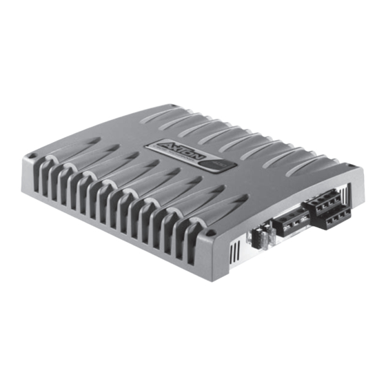
  • Page 45 All manuals and user guides at all-guides.com CONNECTIONS ET RÉGLAGES C109 ENTRÉES L+R: SORTIES: entrées RCA bas niveau à connecter à la source. bornier haut parleur. Impédance mini: 2 ohms. GAIN D’ENTRÉE: INDICATEUR DE MISE EN MARCHE: Permet d’ajuster au mieux les différents niveaux d’entrée.
  • Page 46 All manuals and user guides at all-guides.com Connections et réglages Face avant AXTON C209 et C409 Connections et réglages Face avant AXTON C209 et C409...
  • Page 47 All manuals and user guides at all-guides.com CONNECTIONS ET RÉGLAGES C209/C409 ENTRÉES L+R: +12 V: entrées RCA bas niveau à connecter à la source. à connecter à la borne positive de la batterie. REMOTE: GAIN D’ENTRÉE: signal de mise en marche de l’amplificateur, à connecter à une sor- Permet d’ajuster au mieux les différents niveaux d’entrée.
  • Page 48 All manuals and user guides at all-guides.com Connections et réglages Face avant AXTON C509 Connections et réglages Face avant AXTON C509...
  • Page 49 All manuals and user guides at all-guides.com CONNECTIONS ET RÉGLAGES C509 ENTRÉES L+R CH 1/2: INDICATEUR DE MISE EN MARCHE: entrées RCA avant bas niveau à connecter à la source. ce voyant (vert) indique le bon fonctionnement de l’amplificateur. ENTRÉES L+R CH 3/4: INDICATEUR DE MISE EN PROTECTION: entrées RCA arrière bas niveau à...
  • Page 50 Pour obtenir les meilleurs résultats possibles respectez les conseils donnés ci-dessous : Pour les amplificateurs AXTON, la meilleur position pour la ven- tilation est: amplificateur installé debout. Pour obtenir un signal audio de qualité, utilisez des câbles doubles ou triples blindages haute qualité.
  • Page 51 Il est impératif de placer un fusible principal au maximum à 30 CONNECTER LES cm de la batterie. L’ampérage de ce fusible est déterminé par la C109/C209/C409/C509 consommation de l’installation globale. (voir chapitre E) Le câble de masse (GND) doit être de même section que le câble IMPORTANT: LE CÂBLE D’ALIMENTATION 12 V NE SERA CON-...
  • Page 52 CONTRÔLES ET RÉGLAGES connectez les câbles des haut-parleurs en respectant bien les Selon l’amplificateur AXTON dont vous disposez ( 2 ou 4 canaux) les polarités. Les haut-parleurs doivent avoir une impédance mini modes d’amplifications et de connections seront différents.
  • Page 53 All manuals and user guides at all-guides.com Règle 1: Les haut-parleurs de meilleur qualité sont RÉGLAGE DES FILTRES installés à l’avant du véhicule INTÉGRÉS Règle 2: en se basant sur des haut-parleurs de diamètres et de qualité identiques, la La première opération à effectuer avant même de régler les gains fréquence de coupure des hps avant sera est de sélectionner les bonnes solutions de filtrage.
  • Page 54 All manuals and user guides at all-guides.com ™ 3 – 5 canaux : Augmentez doucement le gain du caisson jusqu'à RÉGLAGES DE LA SENSIBILITÉ DU obtenir de la distorsion, diminuez alors légèrement le gain jusqu'à SYSTÈME ce que la distorsion disparaisse. Réglez ensuite de la même façon les voies avant.
  • Page 55 All manuals and user guides at all-guides.com DÉFAUTS / SOLUTIONS Problème Cause ● +12v, gnd, remote mal connecté Pas de musique, ● fusible principal défectueux Voyant sur l’amplificateur ● fusible sur l’amplificateur défectueux éteint. ● court-circuit sur les sorties Hps ●...
  • Page 56 All manuals and user guides at all-guides.com SPÉCIFICATIONS AXTON AMPLIFICATEUR C109 C209 C409 C509 Puissance de sortie @ 13.8V Stéréo @ 4 ohms W rms 1 x 300 2 x 60 2 x 120 4 x 60 Puissance de sortie @ 13.8V Stéréo @ 2 ohms W rms...
  • Page 57 All manuals and user guides at all-guides.com...
  • Page 58 All manuals and user guides at all-guides.com...
  • Page 59 Dear customer, dirt or dust. Accidents or abuse, unauthorized thank you for buying this AXTON product. It is recom- repair attempts and modifications mended to keep the original packing material for any not explicitly authorized by the future transporting of the product.
  • Page 60 Kundin, oder Stoss; Schäden durch nicht autorisierte Reparaturversuche oder nicht durch den Her- vielen Dank, daß Sie sich zum Kauf eines AXTON-Ge- steller ausdrücklich autorisierte Modifikationen. rätes entschlossen haben. Wir möchten Sie bitten, die Originalverpackung für den Fall einer Garantieleistung...

Ce manuel est également adapté pour:

C209C409C509