TCS 3000 Manuel D'installation
Registre électronique

Sommaire des Matières pour TCS 3000
- Page 1 TCS 3000 L’Installation TCS 3000 Catalog Title ELECTRONIC REGISTER REGISTRE ÉLECTRONIQUE Catalog Subtitle Installation Manual Manuel d’Installation Total Control Systems www.tcsmeters.com...
- Page 2 TCS 3000 L’Installation TCS 3000 Installation Table of Contents Installation du Modem Radio Table des Matières Installation du modem cellulaire Sierra Réception et Inspection Installation du modem cellulaire Maestro Table of Contents Radio Modem Installation Avis Installation de l’affichage à distance Sierra Cellular Modem Installation Receipt &...
-
Page 3: Réception Et Inspection
TCS makes no warranties, express or implied, including the implied warranties of merchantability and fitness for a particular purpose with respect to this manual and, in no event, shall TCS be liable for special or consequential Total Control Systems (TCS) ne peut être tenu responsable d’erreurs techniques ou éditoriales dans ce damages including, but not limited to, loss of production, loss of profits, etc. -
Page 4: Spécifications Du Système
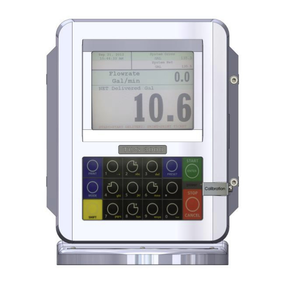
The TCS 3000 register is a fully integrated custody transfer flow computer that will control all vehicle delivery opera- Le registre TCS 3000 est un ordinateur de flux de transfert de propriété entièrement intégré qui contrôlera toutes les opérations tions. The Open Software Architecture provides the option of a simple “Pump & Print” delivery or a custom measure- de livraison de véhicules. - Page 5 TCS 3000 L’Installation TCS 3000 Installation Les ports USB0 et USB1 sont réservés à la maintenance. Pour accéder à ces connecteurs, l’alimentation de The USB0 and USB1 ports are for maintenance only. To access these connectors, power to the unit must be l’unité...
-
Page 6: Procédure D'installation - Compteur Série Tcs 682
4. Faites pivoter le registre TCS 3000 jusqu’à ce que l’écran soit orienté dans la direction souhaitée et vérifiez 4. Rotate the TCS 3000 register until the display is facing in the desired direction and check to see that the meter que les trous du compteur sont alignés sur les trous situés à... -
Page 7: Procédure D'installation - Compteur Série Tcs 700
4. Faites glisser l’accouplement d’entraînement sur l’arbre d’entraînement du compteur. 5. Rotate the TCS 3000 register until the display is facing in the desired direction and check to see that the meter 5. Faites pivoter le registre TCS 3000 jusqu’à ce que l’écran soit orienté dans la direction souhaitée et vérifiez holes align with the holes at the base of the TCS 3000 register. -
Page 8: Procédure D'installation - Montage À Distance 3000
Disposez les pièces comme elles seraient installées. Cela Before beginning the installation of the TCS 3000 register, unpack the entire contents of the packaging in a safe loca- garantira que vous avez toutes les pièces correctes pour l’installation. Le fait de vérifier à l’avance que toutes tion where you will not misplace any of the parts. -
Page 9: Dimensions De La Tcs 3000 À Distance
TCS 3000 L’Installation TCS 3000 Installation TCS 3000 Remote Dimensions Dimensions de la TCS 3000 à Distance 5/16-24 MOUNTING HOLES TROUS DE MONTAGE Total Control Systems www.tcsmeters.com... - Page 10 Coriolis. 2. Place the register on the mounting bracket and rotate the TCS 3000 register until the display is facing in the desired 2. Placez le registre sur le support de montage et faites pivoter le registre TCS 3000 jusqu’à ce que l’écran soit orienté...
- Page 11 Cravates Zip Ties 1/4” Hardware 1/4” Écrous et boulons TCS 300597, Grounding Strap Kit TCS 300597, KIT DE COURROIE DE MISE À LA TERRE Procédure d’Installation: Installation Procedure: MISE À LA TERRE D’UN SIÈGE DE CAMION:: GROUNDING A TRUCK SEAT:...
-
Page 12: Procédure D'installation - Relais De Chronométrage
Relais de Synchronisation à la Mise sous Tension When installing the TCS 3000 register on delivery tank trucks, it is recommended to use a timing relay for safe startup of the TCS Lors de l’installation du registre TCS 3000 sur des camions-citernes de livraison, il est recommandé d’utiliser 3000 registration. - Page 13 TCS 3000 L’Installation TCS 3000 Installation Installation Procedure — Direct Mount Pulser Procédure d’Installation - Pulseur à Montage Direct www.tcsmeters.com Total Control Systems...
-
Page 14: Procédures D'installation - Test Pulser
/ sorties fonctionnent correctement. Le Test Pulser simulera la livraison du produit réel Prior to putting the liquid handling system into service, the distributor can utilize the TCS 3000 register TEST PULSER to verify that sans avoir à... -
Page 15: Procédures D'installation - Pompe Et Régulateur De Pression
2. Vissez le presse-étoupe à l’arrière de l’enregistreur TCS 3000 et fixez-le 2. Screw the cable gland into the back of the TCS 3000 register and au boîtier. tighten into the housing. 3. Passez le contrôle de pompe à l’ordinateur de bord ou au contrôleur 3. -
Page 16: Procédure D'installation - Pompe D'injection D'additif
TCS 3000 L’Installation TCS 3000 Installation Procédure d’Installation - Pompe d’Injection d’Additif Installation Procedure — Additive Injection Pump Il existe deux choix pour gérer les pompes d’injection d’additif; Externe et Piston. There are two selections for managing Additive Injection Pumps; External and Piston. - Page 17 TCS 3000 L’Installation TCS 3000 Installation Installation Procedure — Additive Injection Pump Procédure d’Installation - Pompe d’Injection d’Additif PRESSION: La fonction de pression pour l’injection d’additif PRESSURE: The Pressure function for Additive Injection is to pro- consiste à fournir un signal de sortie positif pendant tout le vide a positive output signal during the entire delivery process to processus de distribution afin de piloter une pompe d’injection...
- Page 18 1. Locate the air eliminator float wiring on the metering system. système de mesure. 2. Installez le presse-étoupe à l’arrière de l’enregistreur TCS 2. Install the cable gland into the back of the TCS 3000 register 3000 et fixez-le au boîtier. and tighten into the housing.
- Page 19 1. Conecte Independente + 24VCC ao Bloco de Terminais L1 no Sensor Vibronic 2. Connect Terminal Block 7 to “GND” and Terminal Block 8 to “Air Elim.” under Air Eliminator Section of the TCS 3000 register. 2. Conecte o Bloco de Terminais 7 a “GND” e o Bloco de Terminais 8 a “Air Elim.”...
-
Page 20: Procédure D'installation - Vanne De Sécurité À 1 Étage Gpl
18 minimum à l’arrière du registre TCS 3000. La vanne 3 voies sera câblée dans le into the back of the TCS 3000 register. The 3 Way valve will be wired into Solenoid 2 on the terminal board. -
Page 21: Procédure D'installation - Vanne De Sécurité À 2 Étage Gpl
4. Une fois que l’électrovanne est câblée, faites passer le fil correspondant, comme indiqué sur la photo, à into the back of the TCS 3000 register. The 3-Way Valve will be wired into Solenoid 1 (S1) on the terminal board l’aide d’un câble blindé... -
Page 22: Procédures D'installation: Soupape De Sécurité À 1 Étage
3. Une fois que l’électrovanne est connectée, faites passer le tured using a minimum of 18 gauge shielded cable into the back câble correspondant comme indiqué sur l’image à l’aide d’un of the TCS 3000 register. câble blindé d’au moins 18 jauge situé à l’arrière du registre TCS 3000. -
Page 23: Procédures D'installation: Vanne Préréglée À 2 Étages
TCS 3000 register. comme indiqué sur l’image en utilisant un câble blindé de calibre 18 minimum à l’arrière du registre TCS 3000. 4. Insert the solenoid wiring into the cable gland. Wire the solenoid into the correct solenoid location on the terminal board. Leave a 4. -
Page 24: Procédures D'installation - Sonde De Température
7. Comprimez le passe-câble sur le registre TCS3000 jusqu’à ce qu’il soit bien ajusté sur le fil de la sonde de 8. Run the temperature probe wiring to the back of the TCS 3000 register. Insert the wiring into the third cable gland température. -
Page 25: Procédures D'installation - Kit De Sonde De Température
TCS 3000 L’Installation TCS 3000 Installation Installation Procedure — Temperature Probe Kit Procédures d’Installation - Kit de Sonde de Température RTD TCS 3000 / Kit Sonde Thermométrique en Aluminium TCS 3000 RTD Probe/Aluminum Thermowell Kit Item TCS 300811 Descrição Qté... -
Page 26: Procédures D'installation - Communication En Guirlande
TCS 3000 L’Installation TCS 3000 Installation Installation Procedure — Daisy Chain Communication Procédures d’Installation - Communication en Guirlande Daisy Chain: Chaîne de communication numérique pour partager des informations et des accessoires Daisy Chain: Daisy Chain est utilisé pour relier plusieurs registres afin d’utiliser une seule imprimante ou un seul modem Daisy Chain is used for linking multiple registers together to use one printer or modem to link multiple registers to the pour lier plusieurs registres à... -
Page 27: Procédures D'installation - Imprimante
TCS 3000 L’Installation TCS 3000 Installation Installation Procedure — Printer Procédures d’Installation - Imprimante BLANC BLEU NOIR PIN 3: TX TRANSMISSION PIN 2: RX PIN 7: MASSE ÉLECTRIQUE ACCUEIL Installation Procedure: Procédures d’Installation: 1. Find a suitable location for the printer appropriate to your application. - Page 28 TCS 3000 L’Installation TCS 3000 Installation TCS 3000 Trousse pour Imprimante à Feuilles Mobiles 12 V CC TCS 3000 Epson Slip 12 VDC Kit Article Qté TCS 300851 TCS 300951 Item TCS 300851 TCS 300951 Metric Métrique Cable Gland TCS 300244 TCS 300254 Presse-étoupe...
- Page 29 TCS 3000 L’Installation TCS 3000 Installation TCS 3000 Trousse pour Type d’Imprimante en Rouleau 12 V CC TCS 3000 Epson Roll 12 VDC Kit Item TCS 300850 TCS 300950 Article Qté TCS 300850 TCS 300950 Metric Métrique Cable Gland TCS 300244 TCS 300254 Presse-étoupe...
- Page 30 * Le modem Bluetooth ne sera pas couplé avec d’autres périphériques, sauf si TCS programme le périphérique en usine * *Bluetooth Modem will not pair with other devices, unless TCS Programs the device at the Factory* www.tcsmeters.com Total Control Systems...
-
Page 31: Procédures D'installation - Relais Temporisé Mise Hors Tension
éteindre le modem et de When installing the TCS 3000 registration on delivery tank trucks with Cellular Modems, it is recommended to provide a timing re- s’enregistrer pour transmettre intégralement tous les enregistrements de livraison. Installez le relais de temps lay for the power off of the modem and register to completely transmit all delivery records. - Page 32 TCS 3000 register terminal board. 1. Câblez le câble de communication à broches 9DB au port 2. Radio modems can be powered within the TCS 3000 register, via the Computer (COMP.) Du bornier du registre TCS 3000. Power Input.
-
Page 33: Procédures D'installation - Modem Cellular Sierra
TCS 3000 register terminal board. BLACK NOIR Computer (COMP.) Du bornier du registre TCS 3000. 2. Cellular modems come with their own Power Cable & Plug. The Red & 2. Les modems cellulaires sont livrés avec leur propre câble White wire must be wired to the External Power Source (accessory switch) d’alimentation et fiche. - Page 34 1. Câblez le câble de communication à broche 15DB au port the TCS 3000 register terminal board. Computer (COMP.) Du bornier du registre TCS 3000. 2. Cellular modems come with a Power Cable & Plug. The Green wire must 2. Les modems cellulaires sont livrés avec un câble be wired to the External Power Source (accessory switch) together.
- Page 35 See Red Lion, Omega or Tekinno serial slave display manuals for RS-485 programming and wiring Instructions. de câblage RS-485. WARNING: The external remote display requires an External Power Source, do not pull power from the TCS 3000 AVERTISSEMENT: L’affichage externe à distance nécessite une source d’alimentation externe, ne tirez pas register.
- Page 36 TCS 3000 L’Installation TCS 3000 Installation Installation Procedure — 1 Channel Communication Installation Procédure d’Installation - Installation d’Une Communication à 1 Canal CARTE DE COMMUNICATION COMMUNICATION BOARD BOULONS BOULONS D’ESPACEMENT D’ESPACEMENT M4 x 14 M4 X 11 STANDOFF M4 X 14 STANDOFF...
- Page 37 TCS 3000 L’Installation TCS 3000 Installation Installation Procedure — Density Sensor Procédure d’Installation - Capteur de Densité Noir Bleu Rouge Instructions de Câblage: Wiring Instructions: 1. Installez la carte de communication monocanal comme décrit à la page 34. 1) Install the single channel communication board as described on page 34.
- Page 38 TCS 3000 L’Installation TCS 3000 Installation Installation Procedure — Differential Pressure (Voltage) Procédures d’Installation - Pression Différentielle (Tension) NOIR BLEU ROUGE GTP 7534 Manomètre Différentiel à Piston à Pression avec Codeur Rotatif GTP 7534 Differential Pressure Piston Gauge with Rotary Encoder Instructions de Câblage:...
- Page 39 TCS 3000 L’Installation TCS 3000 Installation Installation Procedure — Differential Pressure (Current) Procédures d’Installation - Pression Différentielle (Courant) Analog Differential Pressure Sensor Capteur de Pression Différentielle Analogique 1-Canal Dwyer RX (Noir et Bleu) et Com +USUP (Rouge) Wiring Instructions: Instructions de Câblage: 1) Install the single channel communication board as described on page 34.
- Page 40 TCS 3000 L’Installation TCS 3000 Installation Installation Procedure — 1 Tank Level Monitor Procédures d’Installation - Moniteur de Niveau de 1 Réservoir À: Entrée 4-20mA TO: 4-20mA Input du moniteur de réservoir from Tank Monitor Noir Vert Rouge Instructions de Câblage: Wiring Instructions: 1.
-
Page 41: Instructions De Câblage
5) The FAUDI eurofast® connector should be wired with the BROWN wire to +I and BLUE to –I on the IS barrier. 6. Alimentez la barrière IS séparément du registre TCS 3000. 6) Power the IS barrier separately from the TCS 3000 register. 7. Connectez la connexion eurofast au capteur d’eau FAUDI AFGUARD... - Page 42 TCS 3000 L’Installation TCS 3000 Installation Installation Procedure — Water Defense Sensor—Parker Procédures d’Installation - Capteur de Défense Anti-Eau - Parker TO: 4-20mA Input from Water Sensor A: 4-20 mA par Intérieur du Capteur d’Eau - Noir et Retour 4-20mA (Bleu) - 4-20 mA Extérieur (Blanc)
-
Page 43: Procédure D'installation - Installation De Communication À 3 Canaux
TCS 3000 L’Installation TCS 3000 Installation Installation Procedure — 3 Channel Communication Installation Procédure d’Installation - Installation de Communication à 3 Canaux Carte 3 Canaux COMMUNICATION BOARD 3 CH Séparateurs M4 x 14 M4 X 11 STANDOFF M4 X 14 STANDOFF Séparateurs M4 x 11... - Page 44 1. Câblez l’alimentation et la terre pour la carte 3 canaux avec l’alimentation principale et la terre TCS 3000 pour le TCS 3000 2) Wire RS485 Input from 3 Channel Communication board to Periph 485 on Terminal Board 2. Câblez l’entrée RS485 de la carte de communication à 3 canaux à la périphérie 485 du bornier comme montré...
- Page 45 TCS 3000 L’Installation TCS 3000 Installation Installation Procedure — Density Sensor Procédure d’Installation - Capteur de Densité = Terre - Noir - Bleu VS1 (2) (3) - Rouge Instructions de Câblage: Wiring Instructions: 1) Installez la carte de communication à trois canaux comme décrit à la page 41.
- Page 46 TCS 3000 L’Installation TCS 3000 Installation Installation Procedure — Differential Pressure (Voltage) Procédure d’Installation - Pression Différentielle (Tension) - Noir - Bleu VS1 (2) (3) - Rouge **REMARQUE** **NOTE** Lorsque vous utilisez la jauge Gammon When using the Gammon Gauge You MUST Flip...
- Page 47 TCS 3000 L’Installation TCS 3000 Installation Installation Procedure — Differential Pressure (Current) Procédure d’Installation - Pression Différentielle (Courant) 3 Canaux Dwyer - Vo et Com VS1 (2) (3) V dans Les fils de Dwyer Vo et Com sont liés et câblé dans RX sur une carte à 3 canaux Instructions de Câblage:...
-
Page 48: Terre Physique - Noir
TCS 3000 L’Installation TCS 3000 Installation Installation Procedure — 1 Tank Level Monitor Procédure d’Installation - Moniteur de Niveau de 1 Réservoir GND = Terre physique RX = Transmission VS1 = Source de Tension - Noir = Terre physique - Vert... - Page 49 6) Alimentez la barrière IS séparément du registre TCS 3000. 7) Connectez la connexion eurofast au capteur d’eau FUADI AFGUARD ® 6) Power the IS barrier separately from the TCS 3000 register. 7) Connect the eruofast® connection to the FUADI AFGUARD™ water sensor. www.tcsmeters.com Total Control Systems...
- Page 50 TCS 3000 L’Installation TCS 3000 Installation Installation Procedure — Water Defense Sensor—Parker Procédures d’Installation - Capteur de Défense Anti-Eau — Parker Vers: 4-20 mA Out TO: 4-20mA Input du Capteur d’Eau from Water Sensor GND - GND (Noir) et retour 4-20mA (Bleu)
- Page 51 TCS 3000 L’Installation TCS 3000 Installation Installation Procedure — 8 Channel Communication Procédures d’Installation - Communication sur 8 Canaux www.tcsmeters.com Total Control Systems...
- Page 52 TCS 3000 L’Installation TCS 3000 Installation Installation Procedure — 8 Channel Communication—Densitometer Procédures d’Installation - Communication à 8 Canaux - Densitomètre Noir Bleu Rouge www.tcsmeters.com Total Control Systems...
- Page 53 TCS 3000 L’Installation TCS 3000 Installation Procédures d’Installation - Communication sur 8 Canaux - DP - Gammon Installation Procedure — 8 Channel Communication—DP—Gammon Noir Bleu Rouge Total Control Systems www.tcsmeters.com...
- Page 54 TCS 3000 L’Installation TCS 3000 Installation Procédures d’Installation - Communication sur 8 Canaux — DP — Dwyer Installation Procedure — 8 Channel Communication—DP—Dwyer Canaux Dwyer Vo et Com www.tcsmeters.com Total Control Systems...
-
Page 55: Tcs 3000 L'installation
TCS 3000 L’Installation Procédures d’Installation - Communication sur 8 Canaux - Niveaux de Réservoir Noir Vert Rouge... - Page 56 TCS 3000 L’Installation TCS 3000 Installation Installation Procedure — 8 Channel Communication—Water - Faudi Procédures d’Installation - Communication 8 Canaux - Eau - Faudi Marron BROWN = + I Bleu BLUE = - I www.tcsmeters.com Total Control Systems...
- Page 57 TCS 3000 L’Installation TCS 3000 Installation Installation Procedure — 8 Channel Communication—Water - Parker Procédures d’Installation - Communication 8 Canaux - Eau - Parker GND (Noir) et Retour 4-20mA (Bleu) 4-20mA En dehors (Blanc) + VDC (Marron) www.tcsmeters.com Total Control Systems...
-
Page 58: Procédures D'installation De Génération 1 - Mise À Jour De Logiciel
REMARQUE: La nouvelle mise à niveau du logiciel doit être le SEUL fichier sur le lecteur. 2. Open the TCS 3000 register. On the front cover of the register, there are 2 mini-USB connections. Using a factory 2. Ouvrez le registre TCS 3000. Sur la couverture de la caisse enregistreuse, il existe 2 connexions mini- supplied USB cable, attach the thumb drive to the USB port closest to the inside of the register. -
Page 59: Procédure D'installation De Génération 2 - Mise À Jour De Logiciel
USB fournie en usine, connectez la clé USB au port USB situé à l’intérieur du registre. Voir la figure 2. 2. Open the TCS 3000 register. On the front cover of the register, is a USB connection. Using a factory supplied USB, 3. -
Page 60: Image De Génération
TCS 3000 L’Installation TCS 3000 Installation Différences entre les Borniers de Génération 1 et les Borniers de Génération 2 Generation 1 Terminal Board vs. Generation 2 Terminal Board Differences Image de Génération 1 Image de Génération 2 Generation 1 Image Generation 2 Image Compatibilité... -
Page 61: Indicateurs Led
TCS 3000 L’Installation TCS 3000 Installation Indicateurs LED LED I/O Indicators Dedans et Dehors Indicator Lights Advise When There is Power to the Terminal Strip Voyants Indiquent Quand il y a du Pouvoir au Bornier Capacidade de Capacité à Ability to Power... - Page 62 TCS 3000 L’Installation TCS 3000 Installation Interchangeabilité des Générations 1 et 2 Generation 1 & 2 Interchangeability Figure A Figure B Figure B Figure A INCOMPATIBLE COMPATIBLE INCOMPATIBLE COMPATIBLE Relevez le Flip switch up to use Genera- commutateur pour tion 2 Board with Generation utiliser la carte 1 Backing.
-
Page 63: Procédures D'installation - Couverture Avant Du Registre De Remplacement
TCS 3000 L’Installation TCS 3000 Installation Procédures d’Installation - Couverture avant du Registre de Remplacement Installation Procedure — Replacement Register Front Cover HINGE PIN ALLEN SCREW FRONT COVER REPLACEMENT CHARNIÈRE BROCHE ALLEN VIS REMPLACEMENT DU COUVERCLE AVANT SET SCREW SET VIS... - Page 64 CLIP DE RETENUE CONNECTEUR X2 JOINT DE CLAVIER BORNIER AVEC CONNECTEUR CLIP DE RETENUE CONNECTEUR X1 ASSEMBLAGE DE CLAVIER, TCS 3000 ANGLAIS FIL DE TERRE DE 6 ”AVEC COSSE À ANNEAU RADIATEUR RÉSISTANCE AVEC TUBE RÉTRACTABLE VIS À TÊTE CYLINDRIQUE PHILLIPS M4X6 EN ACIER ZINC BATTERIE REMPLAÇABLE...
- Page 65 TCS 3000 L’Installation Total Control Systems www.tcsmeters.com...
-
Page 66: Garantie
TCS; à condition que la ou les pièces soient renvoyées aux frais de transport du TCS en port payé, et que l’examen de TCS révèle que les pièces ou la fabrication étaient défectueuses lors de la livraison à l’acheteur. - Page 67 TCS 3000 L’Installation NOTES Total Control Systems www.tcsmeters.com...
- Page 68 TCS 3000 L’Installation TCS900041 REV. 9 2515 Charleston Place Fort Wayne, IN 46808 Toll Free: (800) 348-4753 Phone: (260) 484-0382 Fax: (260) 484-9230 Email: sales@tcsmeters.com Website: www.tcsmeters.com Total Control Systems www.tcsmeters.com...