JVC VS-DT2000 Manuel D'instructions
Table des Matières
Les langues disponibles
Les langues disponibles
Liens rapides
COMPACT COMPONENT SYSTEM
SYSTEME DE COMPOSANTS COMPACT
VS-DT2000
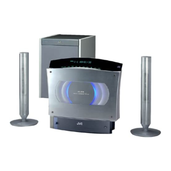
Consists of CA-VSDT2000, SP-VSDT2000 and SP-PW2000
Se compose de CA-VSDT2000, SP-VSDT2000 et SP-PW2000
STANDBY/ON
1
2
3
PLAY MODE
4
5
6
REPEAT
7
8
9
FM MODE
10
+
10
BASS
TREBLE
SET
MD/AUX
CANCEL
FM/AM
DISPLAY
DIMMER
SLEEP
CLOCK
OPEN/
COLOR
/TIMER
CLOSE
VOLUME
SP-VSDT2000
COMPACT COMPONENT SYSTEM
CA-VSDT2000
INSTRUCTIONS
MANUEL D'INSTRUCTIONS
SP-VSDT2000
For Customer Use:
Enter below the Model No. and Serial No.
which are located either on the rear, bot-
tom or side of the cabinet. Retain this
information for future reference.
Model No.
Serial No.
SP-PW2000
LVT0854-002B
[C]
Chapitres
Table des Matières

Manuels Connexes pour JVC VS-DT2000


Sommaire des Matières pour JVC VS-DT2000
-
Page 32: Avertissements Importants
• Grâce à la fonction COMPU PLAY de JVC, vous pouvez mettre la chaîne sous tension et démarrer automatiquement la radio ou le lecteur CD en activant une seule touche. - Page 33 Table des matières Introduction ......................1 Caractéristiques .......................... 1 Structure du mode d’emploi ....................... 1 AVERTISSEMENTS......................... 1 AVERTISSEMENTS IMPORTANTS ..................1 Pour commencer....................3 Accessoires..........................3 Comment installer les piles dans la télécommande..............3 Raccordement de l’antenne FM ....................4 Raccordement de l’antenne AM....................
-
Page 34: Pour Commencer
Pour commencer Accessoires Vérifiez si tous les éléments suivants, fournis avec la chaîne, sont inclus. Cordon d’alimentation (1) Antenne cadre AM (1) Télécommande (1) Piles (2) Fil d’antenne FM (1) Cordon des signaux (1) Entretoises (4) (pour le SP-PW2000) Support (1) (pour appareil central) Pieds (2) (pour support) Vis (1) (pour support) Pattes (2) (pour SP-VSDT2000) -
Page 35: Raccordement De L'antenne Fm
Pour commencer ATTENTION : • Effectuez tous les raccordements avant de brancher la chaîne dans une prise secteur. (Seulement si vous installez l’appareil central verticalement) • Pour placer l’appareil central verticalement, le support et les pieds doivent être montés. (Voir page 8.) Pour effectuer les raccordements, faites passer les cordons dans les orifices du support comme indiqué... -
Page 36: Raccordement De L'antenne Am
Pour commencer Raccordement de l’antenne AM Face arrière de l’appareil central (CA-VSDT2000) SPEAKERS ANTENNA (75 ) COAXIAL DISP.SET CD DIGITAL LOOP SPEAKER IMPEDANCE 4 MD/AUX WOOFER AC IN Antenne cadre AM (fournie) ANTENNA (75 ) COAXIAL LOOP Câble unifilaire extérieur recou- vert de vinyle (en option) Fixez le cadre de l’antenne AM à... -
Page 37: Raccordement Des Haut-Parleurs (Sp-Vsdt2000)
Pour commencer ATTENTION : • Effectuez tous les raccordements avant de brancher la chaîne dans une prise secteur. • Manipulation des haut-parleurs Les haut-parleurs étant des instruments de précision, maniez-les avec précaution de façon à les protéger contre les chocs. Raccordement des haut-parleurs (SP-VSDT2000) Ces enceintes sont conçues exclusivement pour la chaîne. -
Page 38: Fixation Des Entretoises
Pour commencer Fixation des entretoises Fixer les entretoises fournies sur le fond du caisson de grave actif (SP-PW2000) pour protéger le coffret, éviter qu’il ne glisse, et absorber les vibrations du coffret. Décoller le papier protecteur des entretoises et fixer les entretoises. Entretoise (fournie) Fond du caisson de grave actif Raccordement du caisson de grave actif (SP-PW2000) -
Page 39: Raccordement D'un Enregistreur Md (Sortie Numérique)
AC IN ATTENTION : • N’UTILISEZ PAS D’AUTRE CORDON D’ALIMENTATION QUE LE CORDON JVC FOURNI AVEC LE PRESENT APPAREIL POUR EVITER TOUT MAUVAIS FONCTIONNEMENT OU DES DEGATS MATERIELS. • DEBRANCHEZ TOUJOURS LE CORDON D’ALIMENTATION DE LA PRISE SECTEUR LORSQUE VOUS PARTEZ OU QUE VOUS NE Cordon d’alimentation... -
Page 40: Installation De L'équipement Sur Le Mur
Pour commencer Installation de l’équipement sur le mur Il est possible de monter l’appareil central central et les haut-parleurs sur un mur. ATTENTION : Montage sur un mur • Cet appareil central pèse environ 4,3 kg. Lorsque vous utilisez ses touches, une force supplémentaire lui est appliquée dans le sens descendant. -
Page 41: Exemple De Montage (Haut-Parleurs)
Pour commencer Exemple de montage (haut-parleurs) Il est possible de monter les haut-parleurs sur un mur. Montez la patte (fournie) au mur à l’aide de deux vis (en option) et placez le haut-parleur sur la patte. Puis utilisez le boulon à oreilles (fourni) pour fixer fermement le haut-parleur à... -
Page 42: Utilisation De La Télécommande
• Vérifiez que le commutateur “DISP.SET” à l’arrière de l’appareil est réglé correctement. COMPU Play La fonction COMPU PLAY de JVC permet de commander les fonctions les plus utilisées de la chaîne à l’aide d’une seule touche. Les opérations à une seule touche permettent d’écouter un CD, d’allumer la radio, ou d’écouter des appareils externes en ap- puyant simplement sur la touche de lecture correspondant à... -
Page 43: Fonctions De Base
Fonctions de base Témoins de fonctionnement Panneau STANDBY/ON PLAY MODE REPEAT FM MODE SOURCE PRESET Témoin % BASS TREBLE TREBLE BASS MD/AUX CANCEL VOL +/– DISPLAY DIMMER FM/AM DISPLAY DIMMER SLEEP VOLUME +/– CLOCK OPEN/ COLOR /TIMER CLOSE COLOR VOLUME Eclairage COMPACT COMPONENT SYSTEM Témoin de CD introduit... -
Page 44: Changement De La Couleur (Color)
Fonctions de base Changement de la couleur (COLOR) Contrôle de la tonalité (BASS/TREBLE) (Utilisation de la télécommande) Vous pouvez changer la couleur de l’éclairage sur l’appareil. (Utilisation de la télécommande) Appuyer sur la touche % pour mettre la Vous pouvez contrôler la tonalité en modifiant les graves et les aigus. -
Page 45: Utilisation Du Caisson De Grave Actif
Utilisation du caisson de grave actif Témoin STANDBY/ON VOLUME PHASE INPUT (LOW-LEVEL) INPUT (HIGH-LEVEL) POWER Pour ajouter de la richesse au grave (PHASE) Fonctionnement du caisson de Si l’on souhaite ajouter de la richesse au grave, appuyer sur grave actif la touche PHASE pour la régler sur la position “... -
Page 46: Si L'on N'utilise Pas L'appareil Central Ca-Vsdt2000 (Utilisation D'un Autre Appareil)
Utilisation du caisson de grave actif Bornes INPUT (entrée) Le caisson de grave possède les bornes d’entrée (INPUT) suivantes. INPUT (LOW-LEVEL) : Normalement, la borne LEFT/MONO se raccorde à la borne SUBWOOFER de l’élément central à l’aide du cordon de signal fourni. -
Page 47: Utilisation Du Tuner
Utilisation du tuner PRESET+ STANDBY/ON Touches PLAY MODE numériques REPEAT FM MODE FM MODE SOURCE PRESET BASS TREBLE MD/AUX CANCEL SOURCE Gamme d’ondes, fréquences, canal présélectionné FM/AM DISPLAY DIMMER SLEEP FM/AM CLOCK OPEN/ COLOR /TIMER CLOSE VOLUME STEREO MONO Témoins du mode FM * Lors de l’utilisation de la chaîne, d’autres fonctions sont aussi affichées. -
Page 48: Présélection Des Émetteurs
Utilisation du tuner ATTENTION : Présélection des émetteurs • Si l’appareil est débranché ou en cas de panne de courant, les émetteurs présélec- (Utilisation de la télécommande) Vous pouvez ainsi présélectionner jusqu’à 30 émetteurs FM tionnés restent mémorisés pendant environ et jusqu’à... -
Page 49: Utilisation Du Lecteur Cd
Utilisation du lecteur CD Panneau STANDBY/ON Touches PLAY MODE PLAY MODE numériques REPEAT REPEAT SOURCE PRESET FM MODE BASS TREBLE MD/AUX CANCEL Numéro de plage, temps d’écoute, numéro de présélection FM/AM DISPLAY DIMMER SLEEP CLOCK OPEN/ COLOR /TIMER CLOSE OPEN/ VOLUME CLOSE PROGRAM RANDOM... -
Page 50: Retrait D'un Cd
Utilisation du lecteur CD Sélection d’une plage ou d’un passage de ATTENTION : celle-ci • NE PAS essayer d’ouvrir ou de fermer le En mode d’arrêt ou pendant la lecture, appuyez sur la tou- panneau à la main car vous l’endommage- che numérique de la télécommande pour sélectionner la pla- riez. -
Page 51: Lecture En Ordre Quelconque (Aléatoire)
Utilisation du lecteur CD Appuyez sur la touche numérique pour Lecture en ordre quelconque sélectionner la plage à programmer. (aléatoire) Chaque fois que vous appuyez sur la touche numérique, la plage sélectionnée est ajoutée au programme. (Utilisation de la télécommande) •... -
Page 52: Utilisation D'appareils Externes
Utilisation d’appareils externes STANDBY/ON PLAY MODE REPEAT FM MODE BASS TREBLE MD/AUX CANCEL MD/AUX SOURCE PRESET FM/AM DISPLAY DIMMER SLEEP SOURCE CLOCK OPEN/ COLOR /TIMER CLOSE VOLUME Ecoute d’appareils externes Enregistrement de la source du système sur un appareil externe Vous pouvez écouter des appareils externes comme un lec- teur de MD, un platine à... -
Page 53: Utilisation Des Minuteries
Utilisation des minuteries STANDBY/ON PLAY MODE REPEAT FM MODE Heure d’enclenchement ON, heure d’extinction OFF, Source, Volume BASS TREBLE MD/AUX CANCEL Témoin de la minuterie SLEEP FM/AM DISPLAY DIMMER SLEEP SLEEP Témoin SLEEP CLOCK OPEN/ COLOR /TIMER CLOSE CLOCK VOLUME /TIMER * Lorsque l’appareil est en pleine lecture, d’autres fonctions sont aussi affichées. -
Page 54: Réglage De La Minuterie Bonjour
Utilisation des minuteries Programmation de l’heure de désactiva- Réglage de la minuterie Bonjour tion OFF (Exemple: PM 1:30). (Utilisation de la télécommande) 1. Appuyez sur la touche SET. Lorsque vous avez programmé la minuterie Bonjour, celle- Le chiffre de l’heure de désactivation “OFF” program- ci s’enclenche tous les jours à... -
Page 55: Réglage De La Minuterie Bonsoir
Utilisation des minuteries Avant d’éteindre l’appareil, préparez la Réglage de la minuterie Bonsoir source de musique sélectionnée au point 3. (Utilisation de la télécommande) Utilisez la minuterie Bonsoir (SLEEP) pour éteindre l’appa- TUNER: Recherchez l’émetteur souhaité. reil après un certain nombre de minutes. Cette minuterie Insérez un CD. -
Page 56: Entretien - Divers
Entretien - Divers Divers Prenez soin de vos CD afin d’assurer leur bon et long fonc- tionnement. De manière générale, vous obtiendrez toujours les meilleurs Disques compacts résultats en gardant vos CD et les appareils en parfait état de propreté. •... -
Page 57: Dépistage Des Défaillances
Dépistage des défaillances • Si votre chaîne présente certaines défaillances, vérifiez la • Si vous ne parvenez pas à résoudre le problème avec ces liste ci-dessous pour y trouver un remède possible avant indications, ou si l’appareil a été endommagée, deman- de faire appel au service technique. -
Page 58: Caractéristiques
Caractéristiques CA-VSDT2000 Spécifications des enceintes (chaque unité) Amplificateur SP-VSDT2000 38 W (19 W + 19 W) à 4 Ω (Max.) Puissance Haut-parleurs 9,5 cm × 1 cm dôme de type piste 4 Ω Sensibilité/Impédance d’entrée (1 kHz) Impédance MD/AUX IN 500 mV/47 kΩ... - Page 59 Caractéristiques Dimensions pour l’installation (CA-VSDT2000) Position verticale 325 mm (Avec pieds) (Sur le mur) PHONES PHONES 301.5 mm COMPACT COMPONENT SYSTEM 140 mm 105.5 mm Position horizontale 86 mm C O M P A C T C O M P O N E N T S Y S T E M 325 mm 237 mm...
- Page 60 VICTOR COMPANY OF JAPAN, LIMITED EN, FR 0302MNMIDEJEM...