Télécharger Imprimer la page

Publicité

Les langues disponibles
  • FR

Les langues disponibles

  • FRANÇAIS, page 39

Liens rapides

Motor controller
SFC−LAC
Kurzübersicht
Brief overview
SFC−LAC−...−IO
SFC−LAC−...−PB
SFC−LAC−...−CO
SFC−LAC−...−DN
Deutsch
English
Español
Français
Italiano
Svenska
721 137
0707a

Publicité

loading

Sommaire des Matières pour Festo SFC-LAC Serie

  • Page 1 Motor controller SFC−LAC Kurzübersicht Brief overview SFC−LAC−...−IO SFC−LAC−...−PB SFC−LAC−...−CO SFC−LAC−...−DN Deutsch English Español Français Italiano Svenska 721 137 0707a...
  • Page 2 ......... . . Edition: 0707a Original: de © Festo AG & Co. KG, D 73726 Esslingen, Germany, 2007 Internet: http://www.festo.com E−Mail: service_international@festo.com...
  • Page 3 CD−ROM enthalten ist. S Beachten Sie unbedingt die Informationen und Sicherheitshinweise in der vollständigen Beschreibung des Motorcontrollers. S Bitte wenden Sie sich bei technischen Problemen an Ihren lokalen Festo−Service oder an folgende E−Mail− Adresse: service_international@festo.com Festo P.BE−K−SFC−LAC 0707a Deutsch...
  • Page 4 Typ SFC−LAC−...−DN Englisch 555887 Installation und Inbetriebnahme Spanisch 555888 Steuerungsschnittstelle Französisch 555889 DeviceNet Italienisch 555890 usw. Schwedisch 555891 1) Je nach Versionsstand. 2) Dateiname = <Teilenummer> + <Sprachkennung>. Unter dieser Teile− nummer auch als Papierversion erhältlich. Festo P.BE−K−SFC−LAC 0707a Deutsch...
  • Page 5 Weitere Informationen finden Sie im Hilfesystem der Konfi gurationssoftware FCT und in den Bedienungsanleitungen des Zubehörs. Übergeordnete Steuerung Software−Ebene: Festo Configuration Tool (FCT) Controller−Ebene: SFC−LAC Antriebsebene: Festo P.BE−K−SFC−LAC 0707a Deutsch...
  • Page 6 Funktion Statusanzeige > Hauptmenü MENU Menu Eingabe verwerfen oder Menüebene zurück EMERG.STOP Aktuellen Positioniervorgang abbrechen Bestätigt Auswahl bzw. Eingabe Enter SAVE Speichert Parametereinstellungen dauerhaft START/STOP Startet/stoppt Demo−Modus Vorheriger/nächster Menübefehl oder manuell verfahren (Teachen) EDIT Vergrößert/verkleinert Parameterwert Festo P.BE−K−SFC−LAC 0707a Deutsch...
  • Page 7 Steuerung Sub−D, 15−polig E/A−Schnittstelle (SPS/IPC) Stecker Sub−D, 9−polig PROFIBUS−DP−Schnittstelle Buchse Sub−D, 9−polig CANopen−Schnittstelle Stecker Sub−D, 9−polig DeviceNet−Schnittstelle Stecker Spannungs Sub−D, 7W2 Spannungsversorgungs versorgung Stecker anschluss Erdung Stehbolzen M4 Funktionserde (FE) Sub−D, 24W7 Schnittstelle zur HME−... Buchse Festo P.BE−K−SFC−LAC 0707a Deutsch...
  • Page 8 Die LED I/F ist abhängig vom Typ des SFC−LAC: LED I/F SFC−LAC−...−IO Positionier leuchtet grün Betriebsbereit, Freigabe liegt vor status status leuchtet rot Nicht betriebsbereit, Freigabe fehlt (Zweifarb− LED) LED) grün/rot Betriebsbereit, Freigabe fehlt Positionierbetrieb oder Störung Festo P.BE−K−SFC−LAC 0707a Deutsch...
  • Page 9 CAN Zustand stopped" (single flash) CAN Zustand pre−operational" (blinking) Rot: Verbindung fehlerfrei (off ) Verbindung Verbindung CAN Warning Limit reached (single flash) CAN Node Guarding error (double flash) Busparameter nicht parametriert oder externe CAN−Versorgung fehlt (on) Festo P.BE−K−SFC−LAC 0707a Deutsch...
  • Page 10 LED I/F SFC−LAC−...−DN Grün: Zustand Operational" Busstatus (on) "Network" "Network" Zustand Device Standby" (blinking) Rot: Keine Bus−Verbindung No Power/Bus− Busstatus Off (off ) "Module "Module " " Warnung Minor fault" (blinking) Fehler Unrecoverable fault" (on) Festo P.BE−K−SFC−LAC 0707a Deutsch...
  • Page 11 24 VDC ±10 % Leerlaufstrom / Spitzenstrom 0,05 A / 2,1 A (je Ausgang max. 0,5 A) Die Toleranzen für die Spannungsversorgungen müssen auch direkt an den Anschlüssen des SFC−LAC eingehalten werden. Massen verbinden für gleiches Bezugspotenzial ! Festo P.BE−K−SFC−LAC 0707a Deutsch...
  • Page 12 Versorgungskabel 10 m KPWR−MC−1−SUB−15HC− Programmierkabel 2,5 m KDI−MC−M8−SUB−9−... Motorkabel (HME) 10 m KMTR−LAC−S50HC−S50HC−... Steuerkabel 30 m KES−MC−1−SUB−15−... (nur SFC−LAC− −IO) Feldbusstecker/−adapter SFC−LAC−...−PB FBA−2−M12−5POL−RK FBS−SUB−9−GS−DP−B FBS−SUB−9−WS−PB−K FBS−SUB−9−BU−2x5POL−B SFC−LAC−...−CO FBA−2−M12−5POL FBA 2 M12 5POL FBS−SUB−9−WS−CO−K SFC−LAC−...−DN FBA−1−SL−5POL Festo P.BE−K−SFC−LAC 0707a Deutsch...
  • Page 13 Erstinbetriebnahme, nach Änderung der Referenzierungsmethode, nach Änderung des Achsennullpunktes, nach jedem Einschalten oder Ausfall der Logikspan nungsversorgung! Vollziehen Sie die Inbetriebnahme mit dem Festo Configuration Tool (siehe FCT−Hilfesystem) oder mit dem Bedienfeld (nur Typ SFC−LAC−...−H2). Festo P.BE−K−SFC−LAC 0707a Deutsch...
  • Page 14 Probefahrt durchführen. Fahrverhalten, Bezugspunkte und Arbeitsbereich überprüfen. Bei Bedarf Verfahrsätze, Bezugspunkte und Arbeitsbereich optimieren. Feldbus−Adresse des SFC−LAC paramterieren. Funktion der Steuerungsschnittstelle testen. Zum Abschluss der Inbetriebnahme die Hinweise für den Betrieb beachten (siehe Beschreibung zum SFC−LAC−...). Festo P.BE−K−SFC−LAC 0707a Deutsch...
  • Page 15 S You must unconditionally observe the information and the safety instructions in the complete manual of the motor controller. S Please consult your local Festo Service or write to the following e−mail address if you have any technical problems: service_international@festo.com...
  • Page 16 Installation and commissioning Spanish 555888 Control interface DeviceNet French 555889 etc. Italian 555890 Swedish 555891 1) According to version 2) File name = <Part number> + <language code> Also available in the paper version under this part number. Festo P.BE−K−SFC−LAC 0707a English...
  • Page 17 Additional information available in the help system of the FCT configuration software and in the operating instruc tions of the accessories. Master controller Software level: Festo Configuration Tool (FCT) Controller level: SFC−LAC Drive level: Festo P.BE−K−SFC−LAC 0707a English...
  • Page 18 Reject input or return to menu level EMERG.STOP Cancel current positioning procedure Confirms the selection or input Enter SAVE Saves parameter settings permanently START/STOP Starts/stops the Demo mode Previous/next menu command or manual travel (teaching) EDIT Increases/reduces parameter value Festo P.BE−K−SFC−LAC 0707a English...
  • Page 19 Sub−D, 9−pin PROFIBUS−DP interface Socket Sub−D, 9−pin CANopen interface Plug Sub−D, 9−pin DeviceNet interface Plug Power Sub−D, 7W2 Power supply connection supply Plug Earthing Stud bolt, M4 Functional earth (FE) Sub−D, 24W7 Interface to HME−... Socket Festo P.BE−K−SFC−LAC 0707a English...
  • Page 20 The LED I/F depends on the type of SFC−LAC: I/F LED SFC−LAC−...−IO Positioning Illuminated, Ready for operation, is enabled status green (two colour (two−colour Illuminated, Not ready for operation, is not enabled LED) Green/red Ready for operation, is not enabled Positioning mode or defect Festo P.BE−K−SFC−LAC 0707a English...
  • Page 21 CAN status "stopped" (single flash) CAN status "pre−operational" (blinking) Red: Connection error free (off ) connection CAN warning limit reached (single flash) CAN node guarding error (double flash) Bus parameter not parameterised or external CAN supply missing (on) Festo P.BE−K−SFC−LAC 0707a English...
  • Page 22 I/F LED SFC−LAC−...−DN Green: Operational" state Network" (on) bus status bus status Device Standby" status (blinking) Red: No bus connection No Power/Bus−Off" Network" (off ) bus status bus status Warning Minor fault" (blinking) Fault Unrecoverable fault" (on) Festo P.BE−K−SFC−LAC 0707a English...
  • Page 23 I/O supply (only SFC−LAC−...−IO) 24 VDC ±10 % Nominal current/peak current 0.05 A/2.1 A (max. 0.5 A per output) The tolerances for power supply must strictly comply with the SFC−LAC connections. Connect grounds for equal reference potential! Festo P.BE−K−SFC−LAC 0707a English...
  • Page 24 Programming cable 2.5 m KDI−MC−M8−SUB−9−... Motor cable (HME) 10 m KMTR−LAC−S50HC−S50HC−... Control cable 30 m KES−MC−1−SUB−15−... (only SFC−LAC− −IO) Fieldbus plug/adapter Type SFC−LAC−...−PB FBA−2−M12−5POL−RK FBS−SUB−9−GS−DP−B FBS−SUB−9−WS−PB−K FBS−SUB−9−BU−2x5POL−B SFC−LAC−...−CO FBA−2−M12−5POL FBA 2 M12 5POL FBS−SUB−9−WS−CO−K SFC−LAC−...−DN FBA−1−SL−5POL Festo P.BE−K−SFC−LAC 0707a English...
  • Page 25 After the axis zero point is modified Every time the logic voltage supply is connected or after every failure. Carry out commissioning with the Festo Configuration Tool (see FCT help system), or the control panel (only type SFC−LAC−...−H2). Festo P.BE−K−SFC−LAC 0707a English...
  • Page 26 Optimise positioning sets, points of reference and operat ing area as required. Configure field bus address of SFC−LAC. Test function of controller interface. To complete start−up, observe the notes for operation (see description of SFC−LAC−...). Festo P.BE−K−SFC−LAC 0707a English...
  • Page 27 S Es esencial que observe la información y las instrucciones de seguridad en el manual completo del controlador del motor. S Consulte con el servicio local de Festo o escriba a la siguiente dirección de correo electrónico si tiene difi cultades técnicas: service_international@festo.com...
  • Page 28 Francés 555889 etc. Italiano 555890 Sueco 555891 1) Según el estado de la versión. 2) Nombre del archivo = <nº de artículo> + <identificador de idioma>. También disponible en versión impresa con este número de artículo. Festo P.BE−K−SFC−LAC 0707a Español...
  • Page 29 Puede hallar más información en el sistema de ayuda del software de configuración FCT y en las instrucciones de utilización de los accesorios. Unidad de control de nivel superior Nivel de software: Festo Configuration Tool (FCT) Nivel de controla dor: SFC−LAC Nivel de acciona miento: Festo P.BE−K−SFC−LAC 0707a Español...
  • Page 30 Confirmar la selección o la entrada actual Enter SAVE Guardar permanentemente los ajustes de parámetros START/STOP Iniciar/detener el modo Demo Anterior/siguiente orden de menú o desplazar manualmente (programación tipo teach−in) EDIT Aumentar/reducir el valor del parámetro Festo P.BE−K−SFC−LAC 0707a Español...
  • Page 31 Sub−D, 9 pines Interface CANopen Clavija Sub−D, 9 pines Interface DeviceNet Clavija Alimenta Sub−D, 7W2 Conexión para la alimen ción Clavija tación Puesta a Espárrago M4 Tierra funcional (FE) tierra Sub−D, 24W7 Interface a HME−... Zócalo Festo P.BE−K−SFC−LAC 0707a Español...
  • Page 32 El LED I/F depende del tipo del SFC−LAC: LED I/F SFC−LAC−...−IO Estado del Encendido Operacional, está habilitado posiciona en verde miento miento Encendido No operacional, no está habilitado (LED en rojo bicolor) Verde/rojo Operacional, no está habilitado Apagado Modo de posicionamiento o fallo Festo P.BE−K−SFC−LAC 0707a Español...
  • Page 33 Estado del CAN stopped" (single flash) Estado del CAN pre−operational" (blinking) Rojo: Conexión perfecta (OFF) conexión conexión de bus CAN Warning Limit reached (single flash) CAN Node Guarding error (double flash) Bus sin parametrizar o falta alimentación CAN externa (ON) Festo P.BE−K−SFC−LAC 0707a Español...
  • Page 34 Estado Operational" estado (ON) del bus del bus Estado Device Standby" Network" (blinking) Rojo: No hay enlace por bus No Power/ Estado Bus−Off" (OFF) del bus del bus Advertencia Minor fault" Module" (blinking) Error Unrecoverable fault" (ON) Festo P.BE−K−SFC−LAC 0707a Español...
  • Page 35 Corriente sin carga/corriente de pico 0,05 A/2,1 A (por cada salida máx. 0,5 A) Las tolerancias de la alimentación también se deben cumplir en las conexiones de SFC−LAC. Conecte las masas para obtener un potencial de referencia igual. Festo P.BE−K−SFC−LAC 0707a Español...
  • Page 36 Cable del motor (HME) 10 m KMTR−LAC−S50HC−S50HC−... Cable de control 30 m KES−MC−1−SUB−15−... (sólo SFC−LAC− −IO) Clavija/adaptador de bus de Tipo campo SFC−LAC−...−PB FBA−2−M12−5POL−RK FBS−SUB−9−GS−DP−B FBS−SUB−9−WS−PB−K FBS−SUB−9−BU−2x5POL−B SFC−LAC−...−CO FBA−2−M12−5POL FBA 2 M12 5POL FBS−SUB−9−WS−CO−K SFC−LAC−...−DN FBA−1−SL−5POL Festo P.BE−K−SFC−LAC 0707a Español...
  • Page 37 Efectúe la puesta a punto con Festo Configuration Tool (véase la ayuda del sistema FCT) u, opcionalmente, con el panel de control (sólo con el tipo SFC−LAC−...−H2).
  • Page 38 Parametrice la dirección del bus de campo del SFC−LAC. Compruebe el funcionamiento del interface de control. Antes de finalizar la puesta a punto, observe las indicaciones sobre el funcionamiento (véase el manual de SFC−LAC...). Festo P.BE−K−SFC−LAC 0707a Español...
  • Page 39 S En cas de problème technique, veuillez vous adresser au service après−vente Festo le plus proche ou envoyer un courrier électronique à l’adresse suivante : service_international@festo.com Festo P.BE−K−SFC−LAC 0707a Français...
  • Page 40 Espagnol 555888 Interface de commande Français 555889 DeviceNet Italien 555890 etc. Suédois 555891 1) Selon la configuration. 2) Nom de fichier = <référence> + <code de langue>. Egalement disponi ble en version papier sous cette référence. Festo P.BE−K−SFC−LAC 0707a Français...
  • Page 41 Pour plus d’informations, reportez−vous au système d’aide du logiciel de configuration FCT et aux notices d’utilisation des accessoires. Commande de niveau supérieur Niveau logiciel : Festo Configuration Tool (FCT) Niveau contrôleur : SFC−LAC Niveau entraînement : Festo P.BE−K−SFC−LAC 0707a Français...
  • Page 42 Confirmation de la sélection ou de la saisie Enter SAVE Enregistrement permanent des réglages de paramètres START/STOP Lancement/arrêt du mode Démo Passage à la commande de menu précédente/ suivante ou procédure manuelle (Teachen− Apprentissage) EDIT Augmentation/réduction de la valeur du para mètre Festo P.BE−K−SFC−LAC 0707a Français...
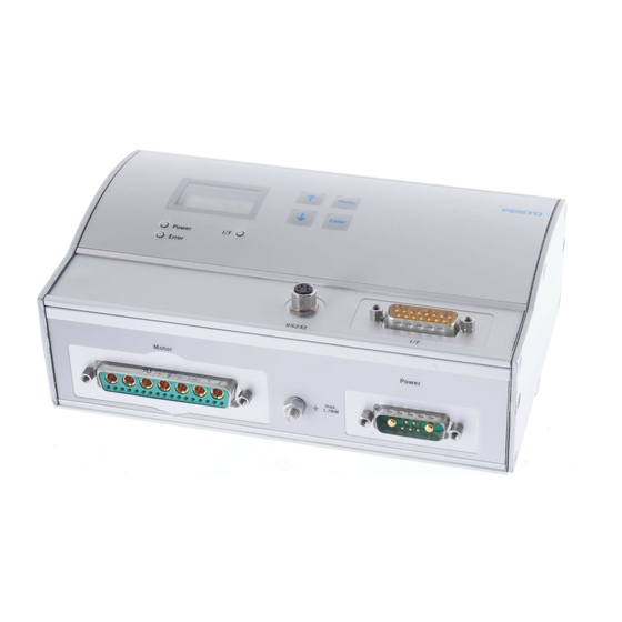
  • Page 43 Sub−D, à 9 pôles Interface DeviceNet Connecteur(s) mâle(s) Alimentation Sub−D, 7W2 Connexion de l’alimenta électrique Connecteur(s) tion électrique mâle(s) Mise à la Goujon M4 Terre du système (FE) terre Sub−D, 24W7 Interface du HME−... Connecteur femelle Festo P.BE−K−SFC−LAC 0707a Français...
  • Page 44 LED I/F SFC−LAC−...−IO Etat de est allumée en Opérationnel, validation disponible positionne vert ment (LED ment (LED est allumée en Non opérationnel, validation bicolore) rouge manquante vert/rouge Opérationnel, validation manquante éteinte Mode de positionnement ou panne Festo P.BE−K−SFC−LAC 0707a Français...
  • Page 45 Etat CAN « pre−operational » (blinking) Rouge : Connexion sans erreur (off) Connexion Connexion CAN Warning Limit reached (single flash) CAN Node Guarding error (double flash) Paramètre de bus non paramétré ou alimentation CAN externe absente (on) Festo P.BE−K−SFC−LAC 0707a Français...
  • Page 46 Etat « Device Standby » (blinking) Rouge : Aucune connexion du bus Etat Etat du bus « No Power/Bus−Off » (off ) « Module » « Module » Avertissement « Minor fault » (blinking) Erreur « Unrecoverable fault » (on) Festo P.BE−K−SFC−LAC 0707a Français...
  • Page 47 0,05 A/2,1 A (par sortie max. 0,5 A) Les tolérances pour les alimentations électriques doivent égale ment être respectées directement au niveau des connecteurs du SFC−LAC. Raccorder les masses pour un même potentiel de référence ! Festo P.BE−K−SFC−LAC 0707a Français...
  • Page 48 10 m KMTR−LAC−S50HC−S50HC−... Câble de commande 30 m KES−MC−1−SUB−15−... (uniquement SFC−LAC− −IO) Connecteur/Adaptateur de Type bus de terrain SFC−LAC−...−PB FBA−2−M12−5POL−RK FBS−SUB−9−GS−DP−B FBS−SUB−9−WS−PB−K FBS−SUB−9−BU−2x5 SFC−LAC−...−CO POLES−B FBA 2 M12 5 POLES FBA−2−M12 5 POLES SFC−LAC−...−DN FBS−SUB−9−WS−CO−K FBA−1−SL−5 POLES Festo P.BE−K−SFC−LAC 0707a Français...
  • Page 49 ! Effectuez la mise en service à l’aide du Festo Configuration Tool (voir le système d’aide FCT) ou du pupitre de commande (uniquement type SFC−LAC−...−H2).
  • Page 50 Paramétrez l’adresse de bus du SFC−LAC. Testez le fonctionnement de l’interface de commande. Pour terminer la mise en service, respectez les consignes d’utilisation (voir notice du SFC−LAC−...). Festo P.BE−K−SFC−LAC 0707a Français...
  • Page 51 S Leggere le informazioni e attenersi alle norme di sicurezza riportate nella descrizione completa del controllore motore. S Se dovessero sorgere problemi tecnici, rivolgersi al servizio assistenza locale Festo o al seguente indi rizzo e−mail: service_international@festo.com Festo P.BE−K−SFC−LAC 0707a Italiano...
  • Page 52 Interfaccia di controllo Francese 555889 DeviceNet Italiano 555890 ecc. Svedese 555891 1) A seconda della versione del sistema. 2) Nome file = <codice prodotto> + <identificazione della lingua>. Disponibile anche in versione cartacea con questo codice prodotto. Festo P.BE−K−SFC−LAC 0707a Italiano...
  • Page 53 Ulteriori informazioni sono riportate nel sistema ausiliario del software di configurazione FCT e nelle istruzioni d’uso degli accessori. Comando principale Livello software: Avviare il Festo Configuration Tool Livello controllore: SFC−LAC Livello di aziona mento: Festo P.BE−K−SFC−LAC 0707a Italiano...
  • Page 54 EMERG.STOP Interrompere processo di posizionamento attuale Conferma selezione o impostazione Enter SAVE Memorizza permanentemente le impostazioni dei parametri START/STOP Avvia/arresta modalità Demo Comando di menu precedente/successivo o traslazione manuale (teach) EDIT Aumenta/riduce valore di parametro Festo P.BE−K−SFC−LAC 0707a Italiano...
  • Page 55 Interfaccia CANopen Connettore SUB−D a 9 poli Interfaccia DeviceNet Connettore Alimenta Sub−D, 7W2 Attacco alimentazione di zione Connettore tensione elettrica Messa a Perni di fissaggio Messa a terra (FE) terra Sub−D, 24W7 Interfaccia per HME−... Connettore femmina Festo P.BE−K−SFC−LAC 0707a Italiano...
  • Page 56 Il LED I/F dipende dal tipo dell’SFC−LAC: LED I/F SFC−LAC−...−IO Stato di verde Pronto, abilitazione presente posiziona posiziona rosso Non pronto, abilitazione mancante mento (LED d (LED a due verde/rosso Pronto, abilitazione mancante colori) colori) Esercizio di posizionamento o guasto Festo P.BE−K−SFC−LAC 0707a Italiano...
  • Page 57 Stato CAN stopped" (single flash) Stato CAN pre−operational" (blinking) Rosso: Collegamento corretto (off ) Collega Collega mento bus CAN Warning Limit reached (single flash) CAN Node Guarding error (double flash) Parametro bus non parametrizzato oppure alimentazione CAN esterna assente (on) Festo P.BE−K−SFC−LAC 0707a Italiano...
  • Page 58 Stato Operational" Stato bus (on) Network" Network" Stato Device Standby" (blinking) Rosso: Collegamento bus assente No Power/ Stato bus Bus Off" (off ) Module Module " " Avvertenza Minor fault" (blinking) Errore Unrecoverable fault" (on) Festo P.BE−K−SFC−LAC 0707a Italiano...
  • Page 59 Corrente a vuoto / corrente di punta 0,05 A / 2,1 A (ogni uscita max. 0,5 A) Sui collegamenti dell’SFC−LAC si devono rispettare le tolleranze per le alimentazioni di tensione. Collegare le masse con lo stesso potenziale di riferimento! Festo P.BE−K−SFC−LAC 0707a Italiano...
  • Page 60 Cavo di programmazione 2,5 m KDI−MC−M8−SUB−9−... Cavo motore (HME) 10 m KMTR−LAC−S50HC−S50HC−... Cavo di comando 30 m KES−MC−1−SUB−15−... (solo SFC−LAC− −IO) Connettore/adattatore Tipo Fieldbus SFC−LAC−...−PB FBA−2−M12−5POL−RK FBS−SUB−9−GS−DP−B FBS−SUB−9−WS−PB−K FBS−SUB−9−BU−2x5POL−B SFC−LAC−...−CO FBA−2−M12−5POL FBA 2 M12 5POL FBS−SUB−9−WS−CO−K SFC−LAC−...−DN FBA−1−SL−5POL Festo P.BE−K−SFC−LAC 0707a Italiano...
  • Page 61 Eseguire la messa in servizio con il software Festo Configuration Tool (vedi guida dell’FCT) o con il pannello di comando (solo tipo SFC−LAC−...−H2). Festo P.BE−K−SFC−LAC 0707a Italiano...
  • Page 62 Ottimizzare, se necessario, record di posizionamento, punti base e range di lavoro. Inserire parametri indirizzo Fieldbus dell’SFC−LAC. Testare la funzione dell’interfaccia di controllo. Al termine della messa in servizio seguire le istruzioni per il funzionamento (vedi descrizione dell’SFC−LAC−...). Festo P.BE−K−SFC−LAC 0707a Italiano...
  • Page 63 S Läs och följ all information och alla säkerhets− anvisningar i den fullständiga beskrivningen till motordrivsteget. S Kontakta närmaste Festo−serviceavdelning eller skriv till följande e−postadress vid eventuella tekniska pro blem: service_international@festo.com Festo P.BE−K−SFC−LAC 0707a Svenska...
  • Page 64 SFC−LAC−...−DN Engelska 555887 Installation och idrifttagning Spanska 555888 Kontrollgränssnitt DeviceNet Franska 555889 osv. Italienska 555890 Svenska 555891 1) Beroende på version. 2) Filnamn = <Artikelnummer> + <Språkkod>. Finns även i pappersver sion med samma artikelnummer. Festo P.BE−K−SFC−LAC 0707a Svenska...
  • Page 65 Ytterligare information finns i hjälpsystemet för konfigura tionsprogrammet FCT och i bruksanvisningarna till tillbe hören. Överordnat styrsystem Programnivå: Festo Configuration Tool (FCT) Controllernivå: SFC−LAC Drivenhetsnivå: Festo P.BE−K−SFC−LAC 0707a Svenska...
  • Page 66 Statusindikering > Huvudmeny MENU Menu Ångra inmatning eller gå tillbaka en menynivå EMERG.STOP Avbryt aktuellt positioneringsförlopp Bekräfta val resp. inmatning Enter SAVE Spara parameterinställningar permanent START/STOP Starta/stoppa demoläge Föregående/nästa menykommando eller manuell körning (inlärning) EDIT Minska/öka parametervärdet Festo P.BE−K−SFC−LAC 0707a Svenska...
  • Page 67 Styrsystem D−sub, 15−polig I/O−gränssnitt (PLC/IPC) Hankontakt D−sub, 9−polig PROFIBUS−DP−gränssnitt Honkontakt D−sub, 9−polig CANopen−gränssnitt Hankontakt D−sub, 9−polig DeviceNet−gränssnitt Hankontakt Spännings D−sub, 7W2 Spänningsförsörjnings försörjning Hankontakt anslutning Jordning Stagbult M4 Funktionsjord (FE) D−sub, 24W7 Gränssnitt för HME−... Honkontakt Festo P.BE−K−SFC−LAC 0707a Svenska...
  • Page 68 LED I/F är beroende av typen av SFC−LAC: LED I/F SFC−LAC−...−IO Positioner Lyser grönt Driftklar, aktivering finns ingsstatus ingsstatus Lyser rött Inte driftklar, aktivering saknas (tvåfärgs− LED) LED) Grön/röd Driftklar, aktivering saknas Släckt Positioneringsläge eller störning Festo P.BE−K−SFC−LAC 0707a Svenska...
  • Page 69 CAN−läge "stopped" (single flash) CAN−läge "pre−operational" (blinking) Röd: Anslutning felfri (off ) Anslutning Anslutning buss CAN Warning Limit reached (single flash) CAN Node Guarding error (double flash) Bussparameter inte parametrerad eller extern CAN−försörjning saknas (on) Festo P.BE−K−SFC−LAC 0707a Svenska...
  • Page 70 LED I/F SFC−LAC−...−DN Grön: Läge "Operational" Busstatus (on) "Network" "Network" Läge "Device Standby" (blinking) Röd: Ingen bussanslutning "No Power/Bus− Busstatus Off" (off ) "Module" "Module" Varning "Minor fault" (blinking) Fel "Unrecoverable fault" (on) Festo P.BE−K−SFC−LAC 0707a Svenska...
  • Page 71 Intern säkring 2,5 A supersnabb I/O−försörjning (endast SFC−LAC−...−IO) 24 VDC ±10 % Tomgångsström/toppström 0,05 A/2,1 A (max. 0,5 A per utgång) Toleransena för spänningsförsörjningen måste också upprätthållas direkt vid anslutningarna på SFC−LAC. Anslut massor för samma referenspotential! Festo P.BE−K−SFC−LAC 0707a Svenska...
  • Page 72 Försörjningskabel 10 m KPWR−MC−1−SUB−15HC− Programmeringskabel 2,5 m KDI−MC−M8−SUB−9−... Motorkabel (HME) 10 m KMTR−LAC−S50HC−S50HC−... Styrkabel 30 m KES−MC−1−SUB−15−... (endast SFC−LAC− −IO) Fältbusskontakt/−adapter SFC−LAC−...−PB FBA−2−M12−5POL−RK FBS−SUB−9−GS−DP−B FBS−SUB−9−WS−PB−K FBS−SUB−9−BU−2x5POL−B SFC−LAC−...−CO FBA−2−M12−5POL FBA 2 M12 5POL FBS−SUB−9−WS−CO−K SFC−LAC−...−DN FBA−1−SL−5POL Festo P.BE−K−SFC−LAC 0707a Svenska...
  • Page 73 ändring av referenskörningsmetoden, efter ändring av axelnollpunkten, efter varje tillkoppling av eller avbrott i logikspän ningsförsörjningen! Slutför idrifttagningen med Festo Configuration Tool (se FCT−hjälpsystem) eller med manöverpanelen (endast typ SFC−LAC−...−H2). Festo P.BE−K−SFC−LAC 0707a Svenska...
  • Page 74 (vid ändring av AZ: förnyad referenskörning). Ange/lär in positionssatser. Genomför provkörning. Kontrollera köregenskaper, referenspunkter och arbetsområde. Optimera vid behov positionssatser, referenspunkter och arbetsområde. Parametrera fältbussadressen för SFC−LAC. Testa funktionen hos kontrollgränssnittet. Observera driftanvisningarna när idrifttagningen avslutas (se beskrivningen till SFC−LAC−...). Festo P.BE−K−SFC−LAC 0707a Svenska...