Table des Matières
Publicité
Les langues disponibles
Les langues disponibles
Liens rapides
Istruzioni ed avvertenze per l'installazione e l'uso
Instructions and warnings for installation and use
Instructions et avertissements pour l'installation et l'usage
Instrucciones y advertencias para su instalación y uso
Anleitungen und Hinweise zu Installation und Einsatz
Instrukcje i zalecenia dotyczące instalacji i użytkowania
Instruções e advertências para a instalação e utilização
VIPER
Motoriduttore sezionale per automazione garage
Opener for sectional and up and over garage door
Motoréducteur sectionnél pour automation garage
Motorreductor seccional para automatismo garaje
Moto-redutor seccional para amolação garagem
Przekrojowa przekładnia zwalniająca do automatyki garażowej
Sektionalantrieb für Garagentorautomation
Publicité
Chapitres
Table des Matières
Dépannage

Manuels Connexes pour Key Automation VIPER


Sommaire des Matières pour Key Automation VIPER
- Page 1 Anleitungen und Hinweise zu Installation und Einsatz Instrukcje i zalecenia dotyczące instalacji i użytkowania Instruções e advertências para a instalação e utilização VIPER Motoriduttore sezionale per automazione garage Opener for sectional and up and over garage door Motoréducteur sectionnél pour automation garage Motorreductor seccional para automatismo garaje Moto-redutor seccional para amolação garagem...
-
Page 2: Table Des Matières
INDICE Avvertenze per la sicurezza pag. 3 Introduzione al prodotto pag. 4 Descrizione del prodotto pag. 4 Composizione pag. 4 Modelli e caratteristiche tecniche pag. 5 Specifiche tecniche pag. 5 Elenco cavi necessari pag. 6 Verifiche preliminari pag. 6 Installazione del prodotto pag. -
Page 3: Avvertenze Per La Sicurezza
Se sostanze liquide penetrano all’interno delle parti dei componenti dell’automazione, scollegare immediatamente l’alimentazione elet- La progettazione e la fabbricazione dei dispositivi che trica e rivolgersi al Servizio Assistenza Key Automation. L’utilizzo compongono il prodotto e le informazioni contenute dell’automazione in tali condizioni può causare situazioni di pericolo;... -
Page 4: Introduzione Al Prodotto
14 m e sezionali fino a 16 m La guida e’ pre-assemblata a catena, in pezzo unico o in tre pezzi. Viper e’ dotato di encoder, centrale di comando e ricevitore a 1 canale integrati. 2.2 Composizione Il sistema di automazione per porte da garage è... -
Page 5: Modelli E Caratteristiche Tecniche
2.3 Modelli e caratteristiche tecniche CODICE DESCIZIONE POTENZA GUIDA per porte sezionali fino a 10 mq con motore 24 Vdc e a catena pre-assemblata 3320 mm in un SEZ7U 700Nm centrale con ricevitore integrato unico pezzo per porte sezionali fino a 10 mq con motore 24 Vdc e a catena 3320 mm in tre pezzi con innesto SEZ7 700Nm... -
Page 6: Elenco Cavi Necessari
2.5 Elenco cavi necessari Nell'impianto tipico i cavi necessari per i collegamenti dei vari dispo- I cavi utilizzati devono essere adatti al tipo di installazione; ad esem- sitivi sono indicati nella tabella elenco cavi. pio si consiglia un cavo tipo H03VV-F per posa in ambienti interni oppure H07RN-F se posato all'esterno. -
Page 7: Fissaggio Della Guida E Del Motore Sulla Porta
4.2 Collegamento del corpo motore alla guida Standard Testa ruotata di 90° 6x15 Vite autofilettante Guida Guida 6x15 Vite autofilettante Staffa di tipo ad U Staffa di tipo ad U Anello di scostamento laterale Anello di scostamento laterale 4.3 Fissaggio della guida e del motore sulla porta Posizionare guida facendo riferimento alla figura Muro MAX 40 cm... -
Page 8: Collegamenti Elettrici
4.5 Collegamenti elettrici ATTENZIONE - Prima di effettuare i collegamenti verificare che la centrale non sia alimentata Schema di cablaggio fotocellula, connessione sicurezza STOP e comando passo passo P/P Il Contatto di STOP emergenza dovrà essere connesso tra n° 2 e n° 3 (CONTATTO NORMALMENTE CHIUSO NC) Il Contatto di passo passo P/P dovrà... -
Page 9: Impostazione Finecorsa In Chiusura
4.9 Impostazione fine corsa in chiusura Premere “+” Premere “P”, “2” lampeggia Premere “-” Chiusura porta per visualizzare “2” Oppure premere “+” O apertura porta Quando la porta si chiude rag- giungendo la posizione ideale, Attenzione!! Al fine di non rilevare falsi ostacoli in chiusura durante premere il tasto “P”... -
Page 10: Impostazione Modalità Ricezione
4.12 Impostazione modalità ricezione La centrale di comando è predisposta per II comando radio di tutti i trasmettitori Key Automation. Premere il tasto “P” per Premere “+” Premere “P”, nel display “1” lam- Premere “+” o “-” per selezionare per visualizzare “5”... -
Page 11: Impostazione Comando Apertura
4.16 Impostazione comando Apertura È Possibile cambiare il funzionamento del comando apre\stop\chiude in solo apre Tramite l’abilitazione di questa funzione il comando P\P permette l’apertura accettando solo la riapertura durante la chiusura . Con funzione “7=1” chiusura automatica abilitata ad ogni comando viene aggiornato il Premere “+”... -
Page 12: Anomalie Di Funzionamento
4.19 Anomalie di funzionamento Oltre alla segnalazione su display, il lampeggiante (se collegato) In questo paragrafo vengono elencate alcune anomalie di funzio- segnala la situazione di errore tramite una sequenza di due lam- namento che si possono presentare. peggi brevi, pausa, due lampeggi brevi. Guasto Cause Soluzione... -
Page 13: Approfondimenti
Key Automation non è però il produttore della vostra nare più a lungo possibile ed in completa sicurezza. Concordate automazione, che è invece il risultato di un’opera di analisi, valu- con il vostro installatore un piano di manutenzione con frequenza tazione, scelta dei materiali, e realizzazione dell’impianto eseguita... - Page 14 INDEX Safety warnings p. 15 Product overview p. 16 Description of the product p. 16 Composition p. 16 Models and characteristics p. 17 Technical specifications p. 17 List of cables needed p. 18 Preliminary checks p. 18 Installing the product p.
-
Page 15: Safety Warnings
If liquid spills into any part of the automation components, immedi- Read the instructions carefully before you start the installation. ately disconnect the power supply and contact the Key Automation Customer Service. The use of the automation under these condi- The design and manufacture of the devices making tions can be dangerous. -
Page 16: Product Overview
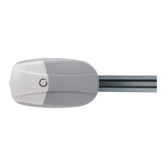
2 - PRODUCT OVERVIEW 2.1 Description of the product Viper has a built-in encoder, control unit and receiver. Viper is an electromechanical irreversible gear motor, suitable to The receiver has the possibility to select fix or rolling code. automate up and over doors up to 14 m and sectional doors up to The rail is chain driven, pre-assembled in one or three pieces. -
Page 17: Models And Characteristics
2.3 Models and characteristics CODE DESCRIPTION POWER GUIDE for sectional doors up to 10 mq with motor 24 Vdc and pre-assembled chain rail 3320 mm in SEZ7U 700Nm central with integrated receiver single piece for sectional doors up to 10 mq with motor 24 Vdc and chain rail 3320 mm into three pieces with SEZ7 700Nm... -
Page 18: List Of Cables Needed
2.5 List of cables needed Typical installation cables required for connection of various devices The cables used must be suitable for the installation; for example, we recommend a H03VV-F type cable for indoor installation and are shown in cables list table. H07RN-F for outdoor. -
Page 19: Connection Of The Motor Body To The Guide
4.2 Connection of the motor body to the guide Standard 90° rotated head 6x15 self tapping screw Guide Guide 6x15 self tapping screw U bracket U bracket lateral movement ring lateral movement ring 4.3 Installation of the guide and motor on the door Position the guide with reference to figure Wall MAX 40 cm... -
Page 20: Wiring Diagram
4.5 Wiring diagram WARNING - Before making connections verify that the installation is not powered Wiring diagram photocell, safety connection STOP and step/step command P/P The emergency STOP contact must be connected between no. 2 and no. 3 (contact normally closed NC) The step/step contact P/P must be connected between no. -
Page 21: Setting Of Closing Limit
4.9 Setting of closing limit Press”+” to display “2” Press “P”, “2” will flash Press”+” Door closing Or press “-” Or door opening When the door closes and reaches the ideal position, after Attention!! In order to avoid false obstacles detection in closing while 2 seconds press the key “P”... -
Page 22: Setting Reception Mode
4.12 Setting reception mode The control unit is set for the radio control of all Key Automation transmitters. Press”+” to display “5” Press “P”, on the display ‘1” Press “+” o “-” to select the Press the key “P” to show “5”, flashes, to indicate that the set desired type of decoding and save the settings. -
Page 23: Opening Command Setting
4.16 Opening command setting It is possible to change the functioning of the open/stop/close command to only open By enabling this function, the Step/Step command permits opening by accepting only re- opening during closing. With the function “7=1” auto- matic closure enabled at each command the automatic closing time is updated Press”+”... -
Page 24: Troubleshooting
4.19 Troubleshooting Together with the warn on the display, the flashing light (if con- In this paragraph it is highlighted some malfunctions that may nected) will warn with a sequence of two short flashes, pause, two happen. short flashes Problem Causes Solution The automation system does not work... -
Page 25: Insights
6 - INSIGHTS 6.1 Battery charger connection 900KBPK Connection sequence: Viper can also function in the absence of main power supply by in- • Disconnect the 230 VAC power supply stalling 900KBPK without making any modifications to the system. • Connect 900KBPK to terminals CH+ and CH- . - Page 26 SOMMAIRE Avertissements pour la sécurité p. 27 Introduction au produit p. 28 Description du produit p. 28 Composition p. 28 Modèles et caractéristiques p. 29 Spécifications techniques p. 29 Liste des câbles nécessaires p. 30 Contrôles préliminaires p. 30 Installation du produit p.
-
Page 27: Avertissements Pour La Sécurité
à l'installation ATTENTION - La société Key Automation Srl se réserve en tenant compte des avertissements suivants : le droit de modifier à tout moment et sans préavis les données et les informations indiquées dans ce manuel. -
Page 28: Introduction Au Produit
2 - INTRODUCTION AU PRODUIT 2.1 - Description du produit Viper est un moteur à engrenage électromécanique irréversible, Viper est doté d’un encodeur intégré, d’une unité de contrôle et d’un récepteur. conçu pour l’automatisation de portes basculantes jusqu’à 14 m ²... -
Page 29: Modèles Et Caractéristiques
2.3 Modèles et caractéristiques CODE DESCRIPTION PUISSANCE GUIDE Pour portes sectionnelles jusqu’a 10 m , moteur 24Vdc, chaîne pré-assemblée 3320 mm pièce SEZ7U 700Nm avec armoire de commande et recepteur unique Pour portes sectionnelles jusqu’a 10 m moteur 24 Vdc, chaîne 3320 mm en 3 pièces avec attache SEZ7 700Nm... -
Page 30: Liste Des Câbles Nécessaires
2.5 Liste des câbles nécessaires Dans le cadre d'une installation type, les câbles nécessaires pour le Les câbles utilisés doivent être adaptés au type d'installation. Par branchement des différents dispositifs sont indiqués dans le tableau de exemple, il est recommandé d'utiliser un câble de type H03VV-F pour la liste des câbles. -
Page 31: Connexion Du Corps Du Moteur Au Rail
4.2 Connexion du corps du moteur au rail Standard Tête pivotée à 90° 6x15 Vis auto-taraudeuse Rail Rail 6x15 Vis auto-taraudeuse Étrier du type en U U bracket Bague d’écartement latéral Bague d’écartement latéral Fixation du corps du moteur au rail positionner le rail en faisant référence à... -
Page 32: Plan De Câblage
4.5 Plan de câblage Attention : Avant d’effectuer les connexions, assurez-vous que l’installation n’est pas sous tension Plan de câblage de la cellule photoélectrique, connexion de sécurité STOP et commande point à point étape par étape L’interrupteur de sécurité STOP doit être connecté entre le n° 2 et le n° 3 (interrupteur normalement fermé NC) L’interrupteur point à... -
Page 33: Configuration Fin De Course En Fermeture
4.9 Configuration fin de course en fermeture Appuyer sur”+” Appuyer sur “P”, “2” clignote Appuyer sur “-” Fermeture porte pour afficher “2” Ou bien appuyer sur “+” Ou ouverture porte Quand la porte se ferme en atteignant la position Idéale, Attention!! A fin de ne pas détecter faux obstacles à... -
Page 34: Configuration Modalité Réception
4.12 Configuration modalité réception L’unité de contrôle est réglée pour le contrôle radio de tous les transmetteurs Key Automation. Appuyer sur”+” Appuyer sur “P”, sur l’écran “1” Appuyer sur ou “-” pour sélec- Appuyer sur la touche “P” pour afficher “5”... -
Page 35: Configuration Commande Ouverture
4.16 Configuration commande Ouverture Il est possible de changer le fonctionnement de la commande ouvrir/arrêt/fermeture uniquement en ouverture Avec l’activation de cette fonction, la commande P\P permet l’ouverture en accep- tant uniquement la réouverture en phase de fermeture. Avec la fonction “7=1” (ferme- ture automatique activée), le temps de fermeture automa- tique est mis à... -
Page 36: Dépannage
4.19 Dépannage En même temps que l’affichage d’alerte sur l’écran, la lumière cligno- Dans ce paragraphe sont soulignés quelques dysfonctionnements qui tante (si elle est connectée) vous avertira avec une séquence de deux peuvent survenir. clignotements rapides, une pause puis deux clignotements rapides Problem Causes Solution... -
Page 37: Approfondissements
Key Automation n'est cependant pas le concepteur toute sécurité. Définir un programme d'entretien à fréquence périodique de votre automation, étant en revanche le résultat d'un travail d'ana- avec l'installateur. - Page 38 ÍNDICE Advertencias de seguridad pág. 39 Introducción al producto pág. 40 Descripción del producto pág. 40 Composición pág. 40 Modelos y características técnicas pág. 41 Modelos y características técnicas pág. 41 Lista cables necesarios pág. 42 Comprobaciones preliminares pág. 42 Instalación del producto pág.
- Page 39 La proyectación y la fabricación de los dispositivos ción eléctrica y diríjase al Servicio de asistencia Key Automation. que componen el producto, así como la información El uso de la automatización en tales condiciones puede originar que contiene esta manual respetan las normativas vi- situaciones peligrosas;...
- Page 40 16 m La guía está pre-montada de cadena, de pieza única o de tres Viper está equipado con un encoder, central de transmisor y piezas. receptor a 1 canal integrados. Composición El sistema de automatización para puertas de garaje se entrega en dos cajas que incluyen el paquete del sistema de automatización y el del ensamblaje de la guia como se muestra a continuación.
- Page 41 2.3 Modelos y características técnicas CÓDIGO DESCRIPCIÓN POTENCIA GUIA Para puerta seccional hasta 10 mq con motor a cadena pre-ensambalda 3320 SEZ7U 700Nm 24 Vdc y central con receptor integrado mm en una pieza única Para puerta seccional hasta 10 mq con motor a cadena 3320 mm tres piezas con SEZ7 700Nm...
- Page 42 2.5 Lista cables necesarios En la instalación típica los cables necesarios para las conexiones Los cables utilizados deben adecuarse al tipo de instalación; por ejemplo se aconseja un cable tipo H03VV-F para instalaciones en de los varios dispositivos se indican de la tabla lista de cables. ambientes interiores o H07RN-F si la instalación es en el exterior.
- Page 43 4.2 Conexión del cuerpo del motor a la guía Estándar Cabeza girada de 90° 6x15 Tornillo autorroscante Guia Guia 6x15 Tornillo autorroscante Brida de tipo en U Brida de tipo en U Anillo de desviación lateral Anillo de desviación lateral 4.3 Fijación del cuerpo motor a la guía coloque la guía según se indica en la figura Pared...
- Page 44 4.5 Conexiones eléctricas ATENCIÓN - Antes de realizar las conexiones controlar que la central no esté alimentada Esquema de cableado fotocélula, conexión seguridad STOP y transmisor paso paso P/P El Contacto de STOP emergencia se deberá conectar entre núm. 2 e núm. 3 (CONTACTO NORMALMENTE CERRADO NC) El Contacto de paso paso P/P se deberá...
- Page 45 4.9 Configuración de fin de carrera en fase de cierre Pulse “+” para visualizar “2” Pulse “P”, “2” parpadea Pulse “+” Cierre puerta O bien pulse “-” O apertura puerta Cuando la puerta se cierre alcanzando la posición ideal, Atención! Con fin de non detectar falsos obstáculos en cierre durante al cabo de 2 segundos pulse el funcionamiento normar se aconseja de non forzar el cierre cuando la tecla “P”...
- Page 46 4.12 Configuración de la modalidad de recepción La central de transmisor está preparada para el control radio de todos los transmisores Key Automation. Pulse “+” para visualizar “5” Pulse “P”; en la pantalla, “1” parpadea, Pulse”+” o”-”, para seleccionar el Pulse la tecla “P”...
- Page 47 4.16 Programación comando apertura Es posible cambiar el funcionamiento del comando abrir/stop/cerrar solo durante la apertura Por medio de la habilitación de esta función, el comando P/P permite la apertura aceptando solo la reapertura durante el cierre. Con función «7=1» (cierre auto- mático habilitado), con cada comando se actualiza el tiempo Pulse “+”...
- Page 48 4.19 Resolución de averías Además de la señal en la pantalla, la luz intermitente (si conecta- En este párrafo se ennumeran algunas anomalías de funciona- da) señala la situación de error mediante una secuencia de dos miento que se pueden presentar. parpadeos breves-pausa-dos parpadeos breves.
- Page 49 útil larga y barreras para aparcamientos y carreteras. Key Automation no es el funcionar de manera segura. Establezca con su instalador un plano productor de su automatización, que es el resultado de una obra de de manutención con frecuencia periódica;...
- Page 50 ÍNDICE Advertências para a segurança pág. 51 Introdução ao produto pág. 52 Descrição do produto pág. 52 Composição pág. 52 Modelos e características técnicas pág. 53 Características técnicas pág. 53 Lista de cabos necessários pág. 54 Verificações preliminares pág. 54 Instalação do produto pág.
- Page 51 A concepção e a produção dos dispositivos que com- trica e dirija-se ao Serviço de Assistência Key Automation. põem o produto e as informações contidas no pre- A utilização da máquina nestas condições pode provocar situações sente manual respeitam as normas vigentes sobre a de perigo.
- Page 52 16 m A guia é pré-montada de corrente, de peça única ou em três Viper está equipado com codificador, central de comando e recetor peças. Composição O sistema de automação para portas de garagem está contido em duas caixas compostas pela embalagem do sistema de automação e a caixa da montagem da guia conforme ilustrado a seguir.
- Page 53 2.3 Modelos e características técnicas CÓDIGO DESCRIÇÃO POTÊNCIA GUIA para portas seccionadas de até 10 m2 com motor 24 de corrente pré-montada de 3320 mm numa SEZ7U 700Nm Vdc e unidade com recetor incorporado única peça para portas seccionadas de até 10 m2 com motor 24 de corrente de 3320 mm em três partes SEZ7 700Nm...
- Page 54 2.5 Lista cabos necessários No sistema típico, os cabos necessários para as ligações dos vários Os cabos utilizados devem ser adequados ao tipo de instalação; por dispositivos estão indicados na tabela da lista de cabos. exemplo, recomenda-se um cabo tipo H03VV-F para cablagem em ambientes internos ou H07RN-F para cablagem no exterior.
- Page 55 4.2 União do corpo do motor à guia Standard Cabeça rodada de 90° 6x15 Parafuso auto-roscante 6x15 Parafuso auto-roscante Guia Guia Suporte tipo sm U Suporte tipo sm U Anel de afastamento lateral Anel de afastamento lateral 4.3 Fixação do corpo do motor à guia posicione a guia usando como referência a figura Muro MAX 40 cm...
- Page 56 4.5 ligações eléctricas ATENÇÃO - Antes de efectuar as ligações, verifique se a central está alimentada Esquema de cablagem fotocélula e conexão segurança STOP e comando passo a passo P/P O Contacto de STOP emergência deverá ser conectado entre n” 2 e n” 3 (CONTACTO NORMALMENTE FECHADO NC) O Contacto da passo a passo P/P deverá...
- Page 57 4.9 Configuração fim de curso de fecho Carregue”+” Carregue “P”, “2” pisca Carregue “-” Fecho porta para visualizar “2” Ou carregue”+” Ou abertura porta Quando a porta abrir atingindo a posição ideal, apãs 2 segundos Atenção!! De forma a não detectar falsos obstáculos no fecho durante carregue a tecla “P”...
- Page 58 4.12 Configuração modalidade de recepção A central de comando está preparada para o comando rádio de todos os transmissores Key Automation. Carregue”+” Carregue em “P”, no ecrã “1” pisca, Carregue”+” oupara seleccio- Carregue a tecla “P” para para visualizar “5”...
- Page 59 4.16 Configuração do comando de Abertura É Possível alterar o funcionamento do comando abre\stop\fecha só na abertura Através da habilitação desta função o comando P\P permite a abertura aceitando só a rea- bertura durante o fecho. Com a função “7=1” (fecho automático habilitado) a cada comando é...
- Page 60 4.19 Resolução de avarias Além da sinalização no visor, o sinal intermitente (se ligado) sinali- Neste parágrafo, são listadas algumas anomalias de funcionamen- za a situação de erro através de uma sequência de duas intermi- to que se podem apresentar. tências breves, pausa, duas intermitências breves.
- Page 61 CH+ e CH-. 7 - INSTRUÇÕES E ADVERTÊNCIAS DESTINADAS AO UTILIZADOR FINAL Key Automation S.r.l. produz sistemas para a automação de por- Manutenção: como qualquer maquinaria, a sua máquina necessita tões, portas de garagem, portas automáticas, persianas, cancelas de uma manutenção periódica para que funcione durante o maior...
- Page 62 SPIS TREŚCI Zalecenia dotyczące bezpieczeństwa str. 63 Wprowadzenie do produktu str. 64 Descrizione del prodotto str. 64 Composizione str. 64 Modelli e caratteristiche tecniche str. 65 Modele i dane techniczne str. 65 Spis niezbędnych przewodów str. 66 Verifiche preliminari str. 66 Montaż...
- Page 63 Musi zostać wypełniona przez wyspecjalizo- obowiązującymi przepisami lokalnymi. wanego technika do spraw instalacji. UWAGA - Key Automation S.r.l. ma prawo do zmian Biorąc pod uwagę sytuacje ryzyka, które mogą zaist- danych i informacji wskazanych w tym podręczniku w nieć...
- Page 64 Prowadnica jest wstępnie zamontowana na łańcuchu, w jednej mentowych do 16 m części lub w trzech częściach. Viper jest wyposażony w enkoder, centralę sterowania i odbiornik o 1 kanale zintegrowanym. 2.2 Skład Automatyczny system do bramy garażowej składa się z dwóch pudełek. Jedno zawiera system automatyczny, podczas gdy drugie zawiera zestaw do montażu prowadnicy, zgodnie z rysunkiem poniżej.
- Page 65 2.3 Modele i dane techniczne OPIS PROWADNICA do bram garażowych o pow. do 10 m2 z silnikiem 24 łańcuchowa, wstępnie zmontowana, o dł. SEZ7U 700Nm VDC oraz z centralą z wbudowanym odbiornikiem 3320 mm, w jednym kawałku do bram garażowych o pow. do 10 m2 z silnikiem 24 łańcuchowa, o dł.
- Page 66 2.5 Spis niezbędnych przewodów W typowej instalacji, przewody konieczne do podłączeń poszcze- Używane przewody muszą być dostosowane do rodzaju instalacji; gólnych urządzeń są wskazane w tabeli spisu przewodów. na przykład zaleca się przewód typu H03VV-F przy montażu w śro- dowisku wewnętrznym lub H07RN-F jeśli umieszczony na zewnątrz TABELA SPIS PRZEWODÓW Połączenie od 1 do 10m...
- Page 67 4.2 Podłączenie silnika do prowadnicy Standard Głowica obrotowa o ok. 90° 6x15 Wkręt samogwintujący 6x15 Wkręt samogwintujący Prowadnica Prowadnica Wspornik U Wspornik U Pierścień ruchu bocznego Pierścień ruchu bocznego 4.3 Przytwierdzanie struktury sillnika do prowadnicy umiejscowić prowadnicę, zgodnie z rysunkiem Ściana MAX 40 cm z łącznikami znajdującymi się...
- Page 68 4.5 Połączenia elektryczne UWAGA - Przed dokonaniem podłączeń należy sprawdzić, czy centrala nie jest zasilana Schemat okablowania fotokomórki, połączenie zabezpieczające STOP i sterowanie krok po kroku P/P Przełącznik polecenia awaryjnego Stop musi zostać podłączony pomiędzy numerem 2 i 3 (Przełącznik normalnie zamknięty NC) Przełącznik polecenia kork po kroku P/P musi zostac podłączony pomiędzy n.
- Page 69 4.9 Regulacja limitu zamykania Naciśnij ”+”, Naciśnij “P”, “2” zacznie Naciśnij “-” Zamykanie bramy aby wyświetlić “2” migać. lub “+” lub otwieranie bramy Po zamknięciu się bramy i osią- gnięciu przez nią idealnej pozycji, Uwaga!! Aby zapobiec wykrywaniu fałszywych przeszkód przy odczekaj 2 sekundy i naciśnij zamykaniu podczas normalnej pracy, zaleca się...
- Page 70 4.12 Regulacja trybu odbioru Centrala sterowania jest przygotowana do sterowania radiowego wszystkich nadajników Key Automation. Naciśnij ”+”, aby wyświetlić Naciśnij przycisk “P”, na ekranie Naciśnij “+” lub “-”, aby wybrać Naciśnij przycisk “P”, aby “5” zacznie migać 1”, aby wskazać, że rodzaj dekodowania wyświetlić...
- Page 71 4.16 Regulacja polecenia otwierania bramy Dokonywanie zmian polecenia otwierania/zatrzymania/zamknięcia bramy możliwe jest wyłącznie w trakcie otwierania bramy. Po aktywacji tej funkcji, polece- nie Krok po Kroku pozwoli na otwarcie bramy tylko w przy- padku ponownego otwierania w trakcie zamykania. Funkcja “7=1” (automatyczne zamykanie aktywne) pozwoli na aktualizację...
- Page 72 4.19 Rozwiązywanie problemów Poza sygnalizacją na wyświetlaczu, lampka ostrzegawcza (jeśli W tym paragrafie wskazano niektóre z błędów jakie mogą się poja- podłączona) sygnalizuje sytuację wystąpienia błędu poprzez se- wić przy funkcjonowaniu systemu. kwencję dwóch krótkich mignięć, przerwy i dwóch długich mignięć. Problem Przyczyny Rozwiązanie...
- Page 73 • Nowe baterie naładują się po około 10 godzinach. 7 - INSTRUKCJE I ZALECENIA DLA UŻYTKOWNIKA KOŃCOWEGO Key Automation S.r.l. produkuje systemy automatyki dla bram, drzwi Odblokowanie i ruch ręczny: przed wykonaniem tej czynności nale- garażowych, drzwi automatycznych, okiennic, szlabanów parkingo- ży zwrócić...
- Page 74 INHALTSVERZEICHNIS Sicherheitshinweise S. 3 Produkteinführung S. 4 Produktbeschreibung S. 4 Zusammensetzung S. 4 Modelle und technische Merkmale S. 5 Technische Merkmale S. 5 Liste der nötigen Kabel S. 6 Vorabkontrollen S. 6 Produktinstallation S. 6 Montage der 3-teiligen Laufschiene S. 6 Anschluss des Motors an der Laufschiene S.
-
Page 75: Sicherheitshinweise
Schild mit der Aufschrift “IN WARTUNG” anbringen. Bei Zweifel jeglicher Art die Installation abbrechen und ggf. Erläuterun- Das Steuergerät muss mit einer Stromleitung verbunden werden, die gen beim Kundendienst Key Automation anfragen. sicher geerdet ist. Für die europäische Gesetzgebung muss der Einbau Dieses Produkt kann nicht als ausreichendes System für den Ein-... -
Page 76: Produkteinführung
Automation von Schwingtoren bis 14 m und Sektionaltoren bis 16 m Die Laufschiene ist mit Kette in einem Stück oder in drei Teilen vor- Viper ist mit einem Encoder, einer Steuereinheit und einem Empfän- montiert. ger mit 1 integrierten Kanal ausgerüstet. -
Page 77: Modelle Und Technische Merkmale
2.3 Modelle und technische Merkmale CODE BESCHREIBUNG LEISTUNG FÜHRUNG für Sektionaltore bis 10 m2 mit Motor 24 VDC und SEZ7U 700Nm mit Kette vormontiert 3320 mm einteilig Steuerung mit eingebautem Empfänger für Sektionaltore bis 10 m2 mit Motor 24 VDC und mit Kette 3320 mm in drei Teilen mit SEZ7 700Nm... -
Page 78: Produktinstallation
2.5 Liste der erforderlichen Kabel Die erforderlichen Kabel einer typischen Anlage für die Verbindung der Die benutzten Kabel müssen dem Installationstyp entsprechen; z.B. einzelnen Vorrichtungen sind in der Tabelle Kabelliste aufgeführt. wird ein Kabel des Typs H03VV-F für Innenbereiche oder H07RN-F für Außenbereiche empfohlen. -
Page 79: Befestigung Der Laufschiene Und Des Motors Am Tor
4.2 Anschluss des Motorkörpers an die Laufschiene Standard Um 90° gedrehter Kopf 6x15 Gewindeschneidschraube Laufschiene Laufschiene 6x15 Gewindeschneidschraube U-förmiger Bügel U-förmiger Bügel Seitlicher Toleranzring Seitlicher Toleranzring Befestigung der Laufschiene und des Motors am Tor Die Laufschiene, wie in der Abbildung gezeigt, positionieren Mauer MAX 40 cm mit den beiliegenden Bügeln... -
Page 80: Anzeige Normalmodus
4.5 Stromanschlüsse ACHTUNG - Bevor die Verbindungen durchgeführt werden, sicherstellen, dass die Stromzufuhr abgeschaltet ist. Verkabelungsplan der Fotozelle, Sicherheitsanschluss STOP und Bedienung Schrittbetrieb P/P Der Not-Aus-Kontakt muss zwischen Nr. 2 und Nr. 3 angeschlossen werden (NORMALERWEISE GESCHLOSSENER KONTAKT NC) Der Schrittbetrieb-Kontakt P/P muss zwischen Nr. 2 und Nr. 1 angeschlossen werden (NORMALERWEISE GEÖFFNETER KONTAKT NA) Display Endschalter Kodierer... -
Page 81: Einstellung Kraftniveau
4.9 Endschalter-Einstellung der Schließung Um “2” anzuzeigen, “P” drücken, “2” blinkt “-” ODER “+” drücken Torschließung “+” drücken oder Toröffnung Wenn sich das Tor schließt und die ideale Stellung erreicht, zum Achtung!! Damit bei einer Schließung im Normalbetrieb keine falschen Speichern der Informationen die Hindernisse erfasst werden, sollte, wenn die Tür bereits den Boden Taste “P”... -
Page 82: Einstellung Empfangsmodus
4.12 Einstellung Empfangsmodus Die Steuereinheit ist für die Funkbedienung aller Key Automation-Sender vorgerüstet. Zur Anzeige von “5”, “P” drücken, auf dem Display blinkt Für die Wahl der gewünschten Zur Anzeige von “5” die Taste “+” drücken. “1” und zeigt damit an, dass die Funk- Dekodifizierung “+”... -
Page 83: Einstellung Öffnungsbedienung
4.16 Einstellung Öffnungsbedienung Man kann den Betrieb der Bedienung öffnen\Stop\schließen in nur öffnen abändern. Durch die Freigabe dieser Funk- tion, ermöglicht die Bedienung P\P die Öffnung und akzeptiert nur die Wiederöffnung während der Schließung. Mit der Funktion “7=1” wird die Zeit der freigegebenen auto- matischen Schließung bei jeder Zur Anzeige von “9”, “+”... -
Page 84: Betriebsstörungen
4.19 Betriebsstörungen Zusätzlich zur Displaymeldung weist das Blinklicht (falls angeschlos- In diesem Absatz werden einige Betriebsstörungen aufgelistet, die sen) mit der Sequenz von zwei kurzen Blinkzeichen, einer Pause und auftreten können. wieder zwei kurzen Blinkzeichen auf den vorliegenden Fehler hin. Beschädigung Ursachen Abhilfe... -
Page 85: Erläuterungen
Türen, Rollläden, sowie Schranken für Parkplätze bedarf Ihre Automation, wie jedes andere Gerät, einer regelmäßigen oder Straßensperren her. Key Automation ist jedoch nicht der Herstel- Wartung. Vereinbaren Sie mit Ihrem Installateur einen Wartungsplan ler Ihrer Automation. Sie ist das Ergebnis von Analysen, Auswertung, mit regelmäßigen Abständen. - Page 86 NOTE...
- Page 87 8 - DICHIARAZIONE DI CONFORMITÀ DICHIARAZIONE “CE” DI CONFORMITÀ DECLARATION OF CONFORMITY “CE” Key Automation S.r.l. Il costruttore: The manufacturer: Indirizzo: Via Alessandro Volta, 30 Noventa di Piave (Ve) Address: DICHIARA CHE IL SEGUENTE APPARATO DECLARES THAT THE FOLLOWING EQUIPMENT...
- Page 88 Key Automation S.r.l. Via A. Volta 30 - 30020 Noventa di Piave (VE) T. +39 0421.307.456 - F. +39 0421.656.98 Instruction version info@keyautomation.it - www.keyautomation.it 580ISSEZCAT rev09...