Key Automation CT202 24 Instructions Et Avertissements Pour L'installation Et L'usage

Key Automation CT202 24 Instructions Et Avertissements Pour L'installation Et L'usage

Logique de commande pour deux moteurs 24 vdc, pour portails battants
Table des Matières

Publicité

Les langues disponibles
  • FR

Les langues disponibles

  • FRANÇAIS, page 34

Liens rapides

Istruzioni ed avvertenze per l'installazione e l'uso
Instructions and warnings for installation and use
Instructions et avertissements pour l'installation et l'usage
Anleitungen und Hinweise zu Installation und Einsatz
Instrucciones y advertencias para su instalación y uso
Instruções e advertências para a instalação e utilização
Instrukcje i zalecenia dotyczące instalacji i użytkowania
CT202 24
Centrale per due motori 24 Vdc, per cancelli a battente
Control unit for two 24 Vdc motors, for swing gates
Logique de commande pour deux moteurs 24 Vdc, pour portails battants
Central para dos motores de 24 Vdc para puertas de batiente
Steuergerät für zwei Drehtor-Motoren 24 Vdc
Unidade para dois motores 24 Vdc, para portões de batente
Centrala dla dwóch silników 24 Vdc, do bram skrzydłowych

Publicité

Table des Matières
loading

Sommaire des Matières pour Key Automation CT202 24

  • Page 1 Instrucciones y advertencias para su instalación y uso Instruções e advertências para a instalação e utilização Instrukcje i zalecenia dotyczące instalacji i użytkowania CT202 24 Centrale per due motori 24 Vdc, per cancelli a battente Control unit for two 24 Vdc motors, for swing gates...
  • Page 2: Table Des Matières

    INDICE Avvertenze per la sicurezza pag. 3 Introduzione al prodotto pag. 5 Descrizione della centrale pag. 5 Descrizione dei collegamenti pag. 5 Modelli e caratteristiche tecniche pag. 5 Elenco cavi necessari pag. 6 Verifiche preliminari pag. 6 Installazione del prodotto pag.
  • Page 3: Avvertenze Per La Sicurezza

    In considerazione di ciò, il collegamento definitivo immediatamente l’alimentazione elettrica e rivolgersi dell’automatismo alla rete elettrica, il collaudo al Servizio Assistenza Key Automation. L’utilizzo dell’impianto, la sua messa in servizio e la dell’automazione in tali condizioni può causare manutenzione periodica devono essere eseguiti situazioni di pericolo;...
  • Page 4 Key Automation si riserva il diritto di modificare guidata che incorpora una porta pedonale; le presenti istruzioni qualora necessario, queste e/o versione superiore si possono trovare sul sito installare qualsiasi comando fisso a un’altezza minima...
  • Page 5: Introduzione Al Prodotto

    La centrale CT20224 è il più moderno ed efficiente sistema di dotata di un display che permette una facile programmazione ed il controllo per i motori Key Automation per l’apertura e la chiusura costante monitoraggio dello stato degli ingressi; inoltre la struttura elettrica di cancelli a battente.
  • Page 6: Caratteristiche Tecniche

    CARATTERISTICHE TECNICHE CT202 24 CT202 24E CT202 24L Alimentazione (L-N) 230Vac (+10%-15%) 50/60 Hz 115Vac (+10%-15%) 50/60 Hz Potenza nominale 210W massimo 280W massimo 210W massimo Uscita alimentazione fotocellule 24Vdc (non regolato) massimo 250mA Uscita alimentazione accessori 24 Vac non regolati 200 mA / 24 Vdc non regolati 250 mA...
  • Page 7: Installazione Del Prodotto

    4 - INSTALLAZIONE DEL PRODOTTO 4.1 - Collegamenti elettrici ATTENZIONE - Prima di effettuare i collegamenti verificare che la centrale non sia alimentata COLLEGAMENTO MOTORI CONNETTORE ALIMENTAZIONI Morsettiera collegamenti alimentazione Fase alimentazione 230 Vac (120 Vac) 50-60 Hz M1 + Alimentazione motore M1 + Neutro alimentazione 230 Vac (120 Vac) 50-60 Hz M1 -...
  • Page 8: Visualizzazione Modalità Normale

    COLLEGAMENTI ELETTICI PER RISPARMIO ENERGETICO CONNETTORI SICUREZZE E COMANDI 24 VAC Alimentazione accessori 24 Vac non regolati, 200 mA (con funzionamento batteria uscita non attiva) 24 VAC Alimentazione accessori 24 Vac non regolati, 200 mA (con funzionamento batteria uscita non attiva) Comune per uscite FLASH-IND-LED FLASH Uscita lampeggiante 24Vdc (non regolato), massimo 15W...
  • Page 9 INDICAZIONI SIGNIFICATO Procedura di riallineamento Cancello fermato senza richiusura automatica Cancello in apertura parziale Cancello in posizione di apertura parziale senza richiusura automatica Cancello aperto con richiusura temporizzata - Tratto lampeggiante conteggio in corso Tratto sostituito da cifra 0..9 conto alla rovescia (ultimi 10s) Cancello aperto parziale con richiusura temporizzata - Tratto lampeggiante conteggio in corso Tratto sostituito da cifra 0..9 conto alla rovescia (ultimi 10s) Apprendimento arrestato causa intervento sicurezze o inversione motore...
  • Page 10: Autoapprendimento Della Corsa

    4.3 - Autoapprendimento della corsa Nell'impianto tipico i cavi necessari per i collegamenti dei vari esempio si consiglia un cavo tipo H03VV-F per posa in ambienti dispositivi sono indicati nella tabella elenco cavi. interni oppure H07RN-F se posato all'esterno. I cavi utilizzati devono essere adatti al tipo di installazione; ad AUTOAPPRENDIMENTO DELLA CORSA E DEI PARAMETRI PRINCIPALI I rallentamenti saranno quelli impostati da menù...
  • Page 11: Apprendimento Di Un Trasmettitore

    7. Raggiunto il punto in cui si desidera inizi il rallentamento in chiusura del motore M2 inviare un comando di SBS. La movimentazione del motore M2 continua a velocità ridotta (display visualizza SC.L.). 8. Al raggiungimento della battuta meccanica del motore M2 il motore M1 parte in chiusura. 9.
  • Page 12: Personalizzazione Dell'impianto | Menu Base

    CANCELLAZIONE DI UN RADIOCOMANDO Se si è in programmazione dell’automazione uscire dal menu premendo il tasto MENU fino a visualizza- re --. Premere il pulsante DOWN (RADIO) per più di 2 secondi fino a che nel display comparirà la scritta “rad”...
  • Page 13 DOWN DOWN DOWN MENU MENU MENU Premere il tasto MENU per 1 Premere i tasti + o – per Premere il tasto MENU veloce- secondo fino a visualizzare il scorrere le funzioni per mente per uscire dal menù. valore fisso per salvare il valore modificare altri parametri.
  • Page 14: Collaudo E Messa In Servizio

    5 - COLLAUDO E MESSA IN SERVIZIO DELL’AUTOMAZIONE Il collaudo dell impianto va eseguito da un tecnico qualificato che previsto dalle normative, in particolare la norma EN12445 che deve effettuare le prove richieste dalla normativa di riferimento indica i metodi di prova per gli automatismi per porte e cancelli. in funzione dei rischi presenti, verificando il rispetto di quanto 5.1 - Collaudo Tutti i componenti dell’impianto devono essere collaudati seguendo...
  • Page 15 PARAMETRI DESCRIZIONE DEFAULT UNITÀ Test costa tE.D. 0 = disabilitato 1 = abilitato LP.o. Apertura parziale Tempo richiusura automatica da parziale (0 = TP.C. disabilitato) Configurazione uscita lampeggiante FP.r. 0 = Fissa 1 = Lampeggiante tP.r. Tempo prelampeggio (0 = disabilitato) Configurazione luce di cortesia 0 = A fine manovra accesa per tempo TCY FC.Y.
  • Page 16 Key Automation non è però il produttore della quando l’anta è ferma. vostra automazione, che è invece il risultato di un’opera di analisi, •...
  • Page 17 NOTE...
  • Page 18 INDEX Safety warnings p. 19 Introducing the product p. 21 Description of the control unit p. 21 Description of the connections p. 21 Models and technical characteristics p. 21 List of cables required p. 22 Preliminary checks p. 22 Product installation p.
  • Page 19: Safety Warnings

    If in any doubt regarding installation, do not proceed and con- tact the Key Automation Technical Service for clarifications. do not allow parts of the automation system to be im- mersed in water or other liquids. During installation...
  • Page 20 Key Automation reserves the right to amend electrical mains; these instructions if necessary; they and/ special care must be taken to avoid crushing between...
  • Page 21: Introducing The Product

    The CT20224 control unit is the most modern, efficient system for CT20224 has a display allowing easy programming and constant the control of Key Automation motors for the electric opening and monitoring of the input status; the menu structure also allows easy closure of swing gates.
  • Page 22: Technical Specifications

    TECHNICAL SPECIFICATIONS CT202 24 CT202 24E CT202 24L Power supply (L-N) 230Vac (+10% - 15%) 50/60 Hz 115Vac (+10%-15%) 50/60 Hz Rated power maximum 210W maximum 280W maximum 210W Photocell power supply output 24Vdc (without regulation) maximum 250mA Output for Vac accessories power...
  • Page 23: Product Installation

    4 - PRODUCT INSTALLATION 4.1 - Electrical connections WARNING - Before making the connections, ensure that the control unit is not powered up. MOTOR CONNECTION POWER SUPPLY CONNECTOR Power supply connection terminal board Power supply live 230 Vac (120 Vac) 50-60 Hz M1 + Power supply of motor M1 + Power supply neutral 230 Vac (120 Vac) 50-60 Hz...
  • Page 24: Display During Normal Operation

    ELECTRICAL CONNECTIONS FOR ENERGY SAVING SAFETY AND CONTROL DEVICE CONNECTORS 24 VAC Accessories power supply 24 Vac without regulation, 200 mA (with battery operation output not active) 24 VAC Accessories power supply 24 Vac without regulation, 200 mA (with battery operation output not active) Common for the FLASH-IND-LED outputs FLASH Flashing light output 24Vdc (without regulation), maximum 15W...
  • Page 25 MESSAGES MEANING Re-alignment procedure Gate stopped without automatic reclosure Gate in partial opening mode Gate in partial opening position without automatic reclosure Gate open with timed reclosure - Flashing dash counting in progress Dash replaced by figures 0..9 countdown (last 10s) Gate in partial opening position with timed reclosure - Flashing dash counting in progress Dash replaced by figures 0..9 countdown (last 10s) Learning stopped due to activation of safety device or motor inversion...
  • Page 26: Autolearning Of The Travel Stroke

    4.3 - Autolearning of the travel stroke The first time the control unit is powered up, an autolearning such as the travel stroke length and deceleration points. procedure must be carried out to acquire fundamental parameters AUTOLEARNING OF THE TRAVEL STROKE AND MAIN PARAMETERS The decelerations will be those set in the menu, with the same percentage during both opening and closing.
  • Page 27: Learning A Transmitter

    7. On reaching the point where motor M2 closing deceleration is required, press SBS. M2 motor movement continues at low speed (the display shows SC.L.) 8. On reaching the mechanical end stop of motor M2, motor M1 starts closing 9. On reaching the point where motor M1 closing deceleration is required, press SBS. M1 motor movement continues at low speed (the display shows SCL) 10.
  • Page 28: Deleting A Remote Control

    DELETING A REMOTE CONTROL If you are in programming mode exit pressing the MENU button until -- appears. Press the DOWN (RADIO) button for more than 2 seconds. Until the display shows the word “rad” (radio), then release the button 1.
  • Page 29 DOWN DOWN DOWN MENU MENU MENU Press the MENU button Press the + and – buttons to Press the MENU button quickly for 1 second to display the scroll through the functions to to quit the menu. parameter in order to save modify other parameters.
  • Page 30: Testing And Commissioning

    5 - TESTING AND COMMISSIONING THE AUTOMATION SYSTEM The system must be tested by a qualified technician, who must the relevant regulatory requirements, especially the EN12445 perform the tests required by the relevant standards in relation standard which specifies the test methods for gate and door to the risks present, to check that the installation complies with automation systems.
  • Page 31 PARAMETERS DESCRIPTION DEFAULT UNIT Edge test tE.D. 0 = off 1 = on LP.o. Partial opening Time for automatic closure from partial opening TP.C. (0=off) Flashing light output setup FP.r. 0 = Steady 1 = Flashing tP.r. Pre-flashing time (0 = off) Courtesy light setup 0 = On at end of operation for time TCY FC.Y.
  • Page 32: Instructions And Warnings For The End User

    7 - INSTRUCTIONS AND WARNINGS FOR THE END USER Key Automation S.r.l. produces systems for the automation of gates, • manual release and operation: first bear in mind that the release garage doors, automatic doors, roller blinds and car-park and road procedure can only be carried out with the door or gate stationery.
  • Page 33 NOTE...
  • Page 34 SOMMAIRE Avertissements en vue de la sécurité p. 35 Présentation du produit p. 37 Description de la logique de commande p. 37 Description des branchements p. 37 Modèles et caractéristiques techniques p. 37 Liste des câbles nécessaires p. 38 Contrôles préliminaires p.
  • Page 35: Avertissements En Vue De La Sécurité

    « Réception et mise en service de l’automati- immédiatement l’alimentation électrique et s’adresser sme ». au service après-vente Key Automation. L’utilisation de l’automatisme dans ces conditions peut être source De plus, il devra se charger de procéder aux essais de danger;...
  • Page 36 à la norme locale en vigueur. du réseau électrique; KEY AUTOMATION se réserve le droit de modifier, les enfants doivent être surveillés afin de s’assurer si nécessaire, les présentes instructions, dont vous qu’ils ne jouent pas avec l’appareil;...
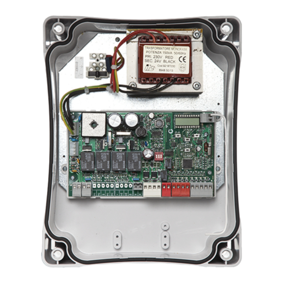
  • Page 37: Présentation Du Produit

    La logique de commande CT20224 est le système de commande le La CT20224 est équipée d’un écran qui permet d’effectuer facilement plus moderne et le plus efficace pour les moteurs Key Automation les opérations de programmation et de surveiller constamment l’état destinés à...
  • Page 38: Caractéristiques Techniques

    CARACTÉRISTIQUES TECHNIQUES CT202 24 CT202 24E CT202 24L Alimentation (L-N) 230Vac (+10% - 15%) 50/60 Hz 115Vac (+10%-15%) 50/60 Hz Puissance nominale maximum 210W maximum 280W maximum 210W Sortie alimentation photocellules 24Vdc (non régulée) maximum 250mA Sortie alimentation des accessoires Vac/ 24 Vac (non régulées) 200 mA / 24 Vdc (non régulées) 250 mA...
  • Page 39: Installation Du Produit

    4 - INSTALLATION DU PRODUIT 4.1 - Branchements électriques ATTENTION - Avant d’effectuer les branchements, vérifier que la logique de commande n’est pas sous tension. BRANCHEMENT MOTEURS CONNECTEUR ALIMENTATIONS Bornier des branchements d’alimentation Phase alimentation 230 Vac (120 Vac) 50-60 Hz M1 + Alimentation moteur M1 + Neutre alimentation 230 Vac (120 Vac) 50-60 Hz...
  • Page 40: Branchements Électriques Pour L'économie D'énergie

    BRANCHEMENTS ÉLECTRIQUES POUR L’ÉCONOMIE D’ÉNERGIE CONNECTEUR DISPOSITIFS DE SÉCURITÉ ET COMMANDES 24 VAC Alimentation accessoires 24 Vac (régulée), 200 mA (avec sortie de l’opération de la batterie non actif) 24 VAC Alimentation accessoires 24 Vac (régulée), 200 mA (avec sortie de l’opération de la batterie non actif) Commun pour les sorties FLASH-IND-LED FLASH Sortie clignotant 24Vdc (non régulée), maximum 15W...
  • Page 41: Alarme Surcharge Àréarmement Manuel

    INDICATIONS SIGNIFICATION Procédure de réalignement Portail arrêté sans refermeture automatique Portail en phase d’ouverture partielle Portail en position d’ouverture partielle sans refermeture automatique Portail ouvert avec refermeture temporisée - Trait clignotant: comptage en cours Trait remplacé par un chiffre entre 0 et 9: compte à rebours (10 dernières secondes) Portail ouvert pour «...
  • Page 42: Autoapprentissage De La Course

    4.3 - Autoapprentissage de la course La première fois que la logique de commande est mise sous permette de détecter des paramètres fondamentaux tels que la tension, il faut exécuter une procédure d’autoapprentissage qui longueur de la course et des ralentissements. AUTOAPPRENTISSAGE DE LA COURSE ET DES PRINCIPAUX PARAMÈTRES Les ralentissements seront conformes aux paramètres sélectionnés dans le menu, avec le même pourcentage en phase d’ouverture qu’en phase de fermeture...
  • Page 43: Apprentissage D'un Émetteur

    7. Quand le portail a atteint le point auquel on souhaite faire commencer le ralentissement en fermeture du moteur M2, envoyer une commande de SBS. Le mouvement actionné par le moteur M2 continue à vitesse lente (l’écran affiche SC.L.) 8. Une fois la butée mécanique d’ouverture du moteur M2 atteinte, le moteur M1 actionne la fermeture 9.
  • Page 44: Effacement D'une Radiocommande

    EFFACEMENT D’UNE RADIOCOMMANDE Si l’on est en phase de programmation de l’automatisme, sortir du menu en pressant la touche MENU jusqu’à l’affichage --. Presser le bouton DOWN (RADIO) pendant plus de 2 secondes jusqu’à ce que l’écran affiche « rad » (radio), puis relâcher le bouton 1.
  • Page 45: Paramètres

    DOWN DOWN DOWN MENU MENU MENU Presser la touche MENU Presser les touches + ou – Presser la touche MENU rapi- pendant 1 seconde jusqu’à pour faire défiler les fonctions, dement pour sortir du menu. l’affichage de la valeur fixe afin de modifier d’autres pour enregistrer mémoriser la paramètres.
  • Page 46: Test Et Mise En Service De L'automatisme

    5 - TEST ET MISE EN SERVICE DE L’AUTOMATISME The system must be tested by a qualified technician, who must the relevant regulatory requirements, especially the EN12445 perform the tests required by the relevant standards in relation standard which specifies the test methods for gate and door to the risks present, to check that the installation complies with automation systems.
  • Page 47 PARAMÈTRES DESCRIPTION DEFAULT UNITÉ Essai barre palpeuse tE.D. 0 = désactivé 1 = activé LP.o. Ouverture partielle Temps de refermeture automatique après ouverture TP.C. partielle (0 = désactivé) Configuration sortie clignotant FP.r. 0 = fixe 1 = clignotant tP.r. Temps préclignotement (0 = désactivé) Configuration éclairage automatique 0 = à...
  • Page 48: Instructions Et Consignes Destinées À L'utilisateur Final

    Nous vous remercions d’avoir choisi Key Automation S.r.l et vous l’installation n’est pas équipée de batteries tampon, l’automatisme invitons à visiter notre site Internet www.keyautomation.it pour plus peut être actionné...
  • Page 49: Remarques

    REMARQUES...
  • Page 50 ÍNDICE Advertencias para la seguridad p. 51 Introducción al producto p. 53 Descripción de la central p. 53 Descripción de las conexiones p. 53 Modelos y características técnicas p. 53 Lista de los cables necesarios p. 54 Controles preliminares p. 54 Instalación del producto p.
  • Page 51: Advertencias Para La Seguridad

    Servicio de Asistencia Key Automation. do las instrucciones indicadas en el apartado “Ensayo Utilizar el automatismo en dichas condiciones podría y puesta en servicio del automatismo”.
  • Page 52 KEY AUTOMATION se reserva la facultad de mo- necte la corriente eléctrica; dificar estas instrucciones de ser necesario, esta tenga mucho cuidado para evitar el aplastamiento en- versión o aquella superior se pueden encontrar en...
  • Page 53: Introducción Al Producto

    La central CT20224 es el sistema de control más moderno y eficiente La central CT20224 incorpora una pantalla que permite programar de los motores Key Automation para la apertura y el cierre eléctrico de fácilmente y monitorizar de manera constante las entradas; además, puertas batientes.
  • Page 54: Lista De Los Cables Necesarios

    CARACTÉRISTIQUES TECHNIQUES CT202 24 CT202 24E CT202 24L Alimentación (L-N) 230Vac (+10% - 15%) 50/60 Hz 115Vac (+10%-15%) 50/60 Hz Potencia nominal máximo 210W máximo 280W máximo 210W Salida alimentación fotocélulas 24Vdc (no regulado) máximo 250mA Salida de alimentación de los accesorios 24 Vac (no regulado) 200 mA / 24 Vdc (no regulado) 250 mA Vac / alimentación test dispositivos Vdc...
  • Page 55: Instalación Del Producto

    4 - INSTALACIÓN DEL PRODUCTO 4.1 - Conexiones eléctricas ATENCIÓN - Antes de realizar las conexiones, compruebe que la central no esté alimentada CONEXIÓN DE LOS MOTORES CONECTOR ALIMENTACIONES Bornier des branchements d’alimentation Fase alimentación 230 Vac (120 Vac) 50-60 Hz M1 + Alimentación del motor M1 + Neutro alimentación 230 Vac (120 Vac) 50-60 Hz...
  • Page 56: Visualisation En Mode Normal

    CONEXIONES ELÉCTRICAS PARA AHORRO DE ENERGÍA CONECTOR DISPOSITIVOS DE SEGURIDAD Y MANDOS 24 VAC Alimentación de los accesorios 24 Vac no regulado, 200 mA (con salida de operación de la batería no activo) 24 VAC Alimentación de los accesorios 24 Vac no regulado, 200 mA (con salida de operación de la batería no activo) Común para las salidas FLASH-IND-LED FLASH Salida luz intermitente 24Vdc (no regulado), máximo 15W...
  • Page 57 INDICATIONS SIGNIFICATION Procedimiento de realineación Puerta detenida sin cierre automático Puerta abriéndose en modo parcial Puerta en posición de apertura parcial sin cierre automático Puerta abierta con cierre temporizado - Guión intermitente conteo en curso Guión sustituido por cifra 0..9 conteo regresivo (últimos 10 s) Puerta abierta parcial con cierre temporizado - Guión intermitente conteo en curso Guión sustituido por cifra 0..9 conteo regresivo (últimos 10 s) Aprendizaje detenido por activación de los dispositivos de seguridad o inversión del motor...
  • Page 58: Autoaprendizaje De La Carrera

    4.3 - Autoaprendizaje de la carrera La primera vez que se alimenta la central debe realizarse un parámetros fundamentales como la longitud de la carrera y las procedimiento de autoaprendizaje que permita detectar los ralentizaciones. AUTOAPRENDIZAJE DE LA CARRERA Y DE LOS PARÁMETROS PRINCIPALES Las ralentizaciones serán aquellas configuradas desde el menú...
  • Page 59: Aprendizaje De Un Transmisor

    7. Cuando se haya alcanzado el punto en que se desea que comience la ralentización durante el cierre del motor M2, envíe un mando de SBS. El movimiento del motor M2 continuará a velocidad lenta (la pantalla visualizará SC.L.) 8. Al llegar al tope mecánico del motor 2, el motor M1 realizará el movimiento de cierre 9.
  • Page 60: Personalización Del Sistema | Menú Básico

    CANCELACIÓN DE UN RADIOMANDO Si usted está dentro del procedimiento de programación del automatismo, salga del menú pulsando MENÚ hasta que se visualice --. Presione el pulsador DOWN (RADIO) durante más de 2 segundos hasta que en la pantalla aparezca escrito “rad” (radio), entonces suelte el pulsador 1.
  • Page 61 DOWN DOWN DOWN MENU MENU MENU Presione el pulsador MENU Presione los pulsadores + Presione el pulsador MENU durante 1 segundo hasta o – para desplazarse por las rápidamente para salir del visualizar el valor fijo para funciones para modificar otros menú.
  • Page 62: Ensayo Y Puesta En Servicio Del Automatismo

    5 - ENSAYO Y PUESTA EN SERVICIO DEL AUTOMATISMO El ensayo del sistema debe ser llevado a cabo por un técnico el cumplimiento de lo previsto por las normativas, especialmente calificado que debe realizar las pruebas requeridas por la normativa la Norma EN 12445 que indica los métodos de ensayos para los de referencia de acuerdo con los riesgos presentes, comprobando automatismos de puertas motorizadas.
  • Page 63 PARÁMETROS DESCRIPCIÓN DEFECTO MÍN. MÁX. UNIDAD Test banda tE.D. 0 = inhabilitado 1 = habilitado LP.o. Apertura parcial Tiempo cierre automático de parcial TP.C. (0 = inhabilitado) Configuración salida luz intermitente FP.r. 0 = Fija 1 = Luz intermitente tP.r. Tiempo destello previo (0 = inhabilitado) Configuración luz de cortesía 0 = Al final del movimiento se enciende durante el...
  • Page 64: Instrucciones Y Advertencias Destinadas Al Usuario Final

    Key Automation no es el detenida. fabricante de su automatización, que es el resultado de una obra •...
  • Page 65 NOTAS...
  • Page 66 INHALTSVERZEICHNIS Sicherheitshinweise p. 67 Einführung in das Produkt p. 69 Beschreibung des Steuergerätes p. 69 Beschreibung der Anschlüsse p. 69 Modelle und technische Eigenschaften p. 69 Liste benötigter Kabel p. 70 Vorabkontrollen p. 70 Produktinstallation p. 71 Stromanschlüsse p. 71 Anzeige Normalmodus p.
  • Page 67: Sicherheitshinweise

    Sollten Flüssigkeiten ins Innere der Automatisie- durchgeführt werden. rungskomponenten dringen, sofort die Stromzufuhr abschalten und sich an den Key Automation Kunden- Außerdem muss das Personal auch die vorgesehenen dienst wenden. Die Benutzung der Automatisierung in Tests nach den vorhandenen Risiken festlegen und derartigen Situationen kann gefährlich sein.
  • Page 68 örtli- chen Bestimmungen entsorgt werden. Bei Hinderniserfassung während des Schließung- smanövers invertiert das Tor die Bewegungsrichtung KEY AUTOMATION behält sich vor, diese Anwei- bis zur vollständigen Öffnung; sungen notfalls zu ändern; diese Anweisungen und/oder eine neuere Version befinden sich auf alle festen Bedienelemente auf einer Höhe von min-...
  • Page 69: Einführung In Das Produkt

    Das Steuergerät CT20224 ist das modernste und effizienteste Das CT20224 ist mit einem Display ausgestattet, das eine einfache Betriebssystem für die Motoren von Key Automation zum Programmierung und kontinuierliche Überwachung des Status der elektrischen Öffnen und Schließen von Drehtore. Jeder andere Eingänge erlaubt.
  • Page 70: Technische Daten

    TECHNISCHE DATEN CT202 24 CT202 24E CT202 24L Spannungsversorgung (L-N) 230Vac (+10% - 15%) 50/60 Hz 115Vac (+10%-15%) 50/60 Hz Nennleistung maximal 210W maximal 280W maximal 210W Ausgang Spannungsversorgung Fotozellen 24Vdc (ungeregelt) maximal 250mA Ausgang Spannungsversorgung Zubehör Vac 24 Vac (ungeregelt) 200 mA / 24 Vdc (ungeregelt) 250 mA / Spannungsversorgung Gerätetest Vdc...
  • Page 71: Produktinstallation

    4 - PRODUKTINSTALLATION 4.1 - Stromanschlüsse ACHTUNG - Vor dem Anschluss sicherstellen, dass die Stromzufuhr des Steuergerätes abgeschaltet ist. ANSCHLUSS DER MOTOREN STROMVERBINDER Klemmenleiste Versorgungsanschlüsse Phase 230 Vac (120 Vac) 50-60 Hz M1 + Stromversorgung Motor M1 + Nullleiter 230 Vac (120 Vac) 50-60 Hz M1 - Stromversorgung Motor M1 - Erde...
  • Page 72: Anzeige Normalmodus

    STROMANSCHLÜSSE FÜR ENERGIEEINSPARUNG VERBINDER FÜR SICHERHEITSVORRICHTUNGEN UND BEDIENELEMENTE 24 VAC Spannungsversorgung Zubehör 24 Vac ungeregelt, 200 mA (mit Batteriebetrieb Ausgang nicht aktiv) 24 VAC Spannungsversorgung Zubehör 24 Vac ungeregelt, 200 mA (mit Batteriebetrieb Ausgang nicht aktiv) Gemeinsamer Leiter für Ausgänge FLASH-IND-LED FLASH Ausgang Blinkleuchte 24Vdc (ungeregelt), maximal 15W Ausgang IND Ausgang Kontrolllampe Tor geöffnet 24 Vdc ungeregelt 5W MAX / Ausgang Elektroschloss 12Vac,...
  • Page 73 ANZEIGEN BEDEUTUNG Verfahren zum Ausrichten Tor ohne automatisches Wiederschließen angehalten Toröffnung für Teilöffnung Tor in Position Teilöffnung ohne automatisches Wiederschließen Tor geöffnet mit zeitgesteuertem Wiederschließen - Blinkender Strich Zeitkontrolle läuft Strich durch Zahl 0..9 ersetzt Rückwärtszählen zum Start (letzte 10 s) Tor geöffnet für Teilöffnung mit zeitgesteuertem Wiederschließen - Blinkender Strich Zeitkontrolle läuft Strich durch Zahl 0..9 ersetzt Rückwärtszählen zum Start (letzte 10 s) Lernvorgang unterbrochen durch ausgelöste Sicherheitsvorrichtungen oder Reversierung des Motors...
  • Page 74: Einlernen Des Laufs

    4.3 - Einlernen des Laufs Bei der ersten Stromversorgung des Steuergeräts muss grundlegender Parameter wie Lauflänge und Verlangsamungen ein Einlernvorgang durchgeführt werden, der die Ermittlung erlaubt. EINLERNEN DES LAUFS UND DER HAUPTPARAMETER Die Verlangsamungen werden entsprechend der Einstellung im Menü durchgeführt werden, wobei der Prozentwert sowohl beim Öffnen als auch beim Schließen gleich ist ACHTUNG: Soll auch die Verlangsamung manuell programmiert werden, fahren Sie bitte direkt mit der folgenden Tabelle fort...
  • Page 75: Lernfunktion Eines Senders

    7. Bei Erreichen des Punktes, an dem die Verlangsamung während der Schließbewegung von Mo- tor M2 beginnen soll, Befehl für den Schrittbetrieb (SBS) erteilen Die Bewegung von Motor M2 wird mit verlangsamter Geschwindigkeit fortgesetzt (Display zeigt SC.L. an) 8. Sobald der Motor M2 den mechanischen Anschlag erreicht, startet der Motor M1 zur Schließung 9.
  • Page 76: Benutzerdefinierte Einrichtung Der Anlage | Grundmenü

    LÖSCHEN EINER FUNKSTEUERUNG Wenn man sich in der Programmierungsphase des Antriebes befindet, das Menü mit dem Taster MENÜ verlassen bis der Schriftzug --erscheint. Über 2 Sekunden lang auf den Taster DOWN (FUNK) drücken, bis auf dem Display die Meldung “rad” (Funk) erscheint; danach den Taster wieder loslassen 1.
  • Page 77 DOWN DOWN DOWN MENU MENU MENU Zur Speicherung des Zum Scrollen der Funktionen Zum Verlassen des Menüs geänderten Werts 1 Sekunde für die Änderung anderer kurz die Taste MENU drücken. lang die Taste MENU drücken, Parameter die Taste + oder – bis der Wert dauerhaft angezeigt drücken.
  • Page 78: Test Und Inbetriebnahme Der Automation

    5 - TEST UND INBETRIEBNAHME DER AUTOMATION Die Endabnahme der Anlage muss von einem qualifizierten Prüfungen ausführt und die Einhaltung der Anforderungen prüft. Techniker durchgeführt werden, der die durch die einschlägigen Besonders zu berücksichtigen ist hierbei die Norm EN12445, welche Bestimmungen je nach bestehenden Gefahren vorgesehenen die Prüfverfahren für Automationen an Türen und Toren festlegt.
  • Page 79 PARAMETER BESCHREIBUNG STANDARD EINHEIT Test Leiste tE.D. 0 = deaktiviert 1 = aktiviert LP.o. Teilöffnung Automatische Wiederschließzeit von Teilöffnung TP.C. (0 = deaktiviert) Konfiguration Blinkleuchtenausgang FP.r. 0 = Dauerhaft 1 = Blinkend tP.r. Vorblinkzeit (0 = deaktiviert) Konfiguration zusätzliche Beleuchtung 0 = Bei Bewegungsende über Zeitdauer TCY eingeschaltet FC.Y.
  • Page 80: Anweisungen Und Hinweise Für Den Endbenutzer

    Sicherheitsvorrichtungen muss schnellstmöglich die Reparatur der Bestimmungen entsorgen. Automation veranlasst werden; • Wir danken Ihnen, dass Sie Key Automation S.r.l. gewählt haben, bei Beschädigungen oder Stromausfall: Während Sie auf den und laden Sie ein, für weitere Informationen unsere Internetseite www.keyautomation.it zu besuchen.
  • Page 81 ANMERKUNGEN...
  • Page 82 ÍNDICE Avisos sobre a segurança p. 83 Informações sobre o produto p. 85 Descrição da unidade p. 85 Descrição das ligações p. 85 Modelos e características técnicas p. 85 Lista de cabos necessários p. 86 Controlos preliminares p. 86 Instalação do produto p.
  • Page 83: Avisos Sobre A Segurança

    Assistên- devem ser feitas por pessoal qualificado e experiente, cia Key Automation. A utilização da automação nestas respeitando as instruções indicadas na caixa “Ensaio condições pode causar situações de perigo;...
  • Page 84 A KEY AUTOMATION reserva-se o direito de mo- dificar estas instruções se necessário. Esta instalar qualquer controlo fixo a uma altura de, pelo versão ou versão superior encontra-se no sítio...
  • Page 85: Informações Sobre O Produto

    A unidade CT20224 é o mais moderno e eficiente sistema de que permite programar facilmente e monitorizar constantemente controlo para os motores Key Automation para a abertura e o fecho o status das entradas; além disso, a estrutura em menu permite elétrico de portões de batente.
  • Page 86: Características Técnicas

    CARACTERÍSTICAS TÉCNICAS: CT202 24 CT202 24E CT202 24L Alimentação (L-N) 230Vac (+10% - 15%) 50/60 Hz 115Vac (+10%-15%) 50/60 Hz Potência nominal 210W máximo 280W máximo 210W máximo Saída de alimentação das fotocélulas 24Vdc (não regulado) máximo 250mA Saída alimentação acessórios Vac / 24 Vac (não regulado) 200 mA / 24 Vdc (não regulado) 250 mA...
  • Page 87: Instalação Do Produto

    4 - INSTALAÇÃO DO PRODUTO 4.1 - Ligações elétricas ATENÇÃO - Antes de fazer as ligações, verificar se a unidade não está ligada à alimentação elétrica. LIGAÇÃO DOS MOTORES CONECTOR DAS ALIMENTAÇÕES Klemmenleiste Versorgungsanschlüsse Fase da alimentação 230 Vac (120 Vac) 50-60 Hz M1 + Alimentação do motor M1 + Neutro da alimentação 230 Vac (120 Vac) 50-60 Hz...
  • Page 88: Visualização No Modo Normal

    LIGAÇÕES ELÉTRICAS PARA POUPANÇA DE ENERGIA CONECTOR SEGURANÇAS E COMANDOS 24 VAC Alimentação dos acessórios 24 Vac não regulado, 200 mA (com a saída de operação da bateria não ativa) 24 VAC Alimentação dos acessórios 24 Vac não regulado, 200 mA (com a saída de operação da bateria não ativa) Comum para saídas FLASH-IND-LED FLASH Saída da luz de sinalização 24Vdc (não regulado), máximo 15W...
  • Page 89 INDICAÇÕES SIGNIFICADO Procedimento de realinhamento Portão parado sem fecho automático Portão na abertura para parcial Portão na posição de abertura para parcial sem fecho automático Portão aberto com fecho temporizado - Traço intermitente contagem em curso Traço substituído por cifra 0..9 contagem regressiva (últimos 10 s) Portão aberto para parcial com fecho temporizado - Traço intermitente contagem em curso Traço substituído por cifra 0..9 contagem regressiva (últimos 10 s) Aprendizagem interrompida por causa da atuação das seguranças ou inversão do motor...
  • Page 90: Autoaprendizagem Do Curso

    4.3 - Autoaprendizagem do curso Quando a unidade for alimentada pela primeira vez, deve ser os parâmetros fundamentais como o comprimento do curso e dos feito um procedimento de autoaprendizagem que permita obter abrandamentos. AUTOAPRENDIZAGEM DO CURSO E DOS PARÂMETROS PRINCIPAIS Os abrandamentos serão os configurados através do menu com o mesmo percentual, quer na abertura, quer no fecho.
  • Page 91: Memorização De Um Emissor

    7. Alcançado o ponto em que se deseja começar o abrandamento no fecho do motor M2, enviar um comando de SBS. A movimentação do motor M2 continua a baixa velocidade (o ecrã apresenta SC.L.) 8. Alcançado o batente mecânico do motor M2, o motor M1 aciona o fecho 9.
  • Page 92: Personalização Do Sistema | Menu Básico

    ELIMINAÇÃO DE UM RADIOCOMANDO Durante a programação da automação, prima a tecla MENU para fechar o menu até aparecer a escrita --. Prima a tecla “DOWN” (RÁDIO) durante mais de dois segundos até aparecer no ecrã a mensagem “rad” (rádio), e então pode soltar a tecla 1.
  • Page 93: Parâmetros

    DOWN DOWN DOWN MENU MENU MENU Premer a tecla MENU durante Premer as teclas + ou – para Premer a tecla MENU 1 segundo até visualizar o valor percorrer as funções para rapidamente para sair do de forma fixa para guardar o modificar outros parâmetros.
  • Page 94: Ensaio E Colocação Em Serviço

    5 - ENSAIO E COLOCAÇÃO EM SERVIÇO O ensaio do sistema deve ser feito por um técnico qualificado que normas, sobretudo a norma EN 12445 que estabelece os métodos deve efetuar os testes previstos pela norma de referência de acordo de ensaio dos automatismos para portas e portões.
  • Page 95 PARÂMETROS DESCRIÇÃO DEFAULT MÍN. MÁX. UNIDADE Teste barra de apalpação tE.D. 0 = desabilitado 1 = habilitado LP.o. Abertura para parcial Tempo de fecho automático após abertura parcial partielle TP.C. (0 = desabilitado) Configuração da saída da luz de sinalização FP.r.
  • Page 96: Instruções E Avisos Para O Utilizador Final

    7 -INSTRUÇÕES E AVISOS PARA O UTILIZADOR FINAL • A Key Automation S.r.l. produz sistemas para a automação de desbloqueio e movimentação manual: para poder desbloquear, a portões de entrada, de garagem, portas automáticas, portas de folha deve estar parada.
  • Page 97 OBSERVAÇÕES...
  • Page 98 SPIS TREŚCI Uwagi dotyczące bezpieczeństwa p. 99 Informacje ogólne p. 101 Opis centrali p. 101 Opis podłączeń p. 101 Modele i parametry techniczne p. 101 Wykaz niezbędnych przewodów elektrycznych p. 102 Kontrole wstępne p. 102 Montaż produktu p. 103 Podłączenia elektryczne p.
  • Page 99: Uwagi Dotyczące Bezpieczeństwa

    Ponadto wspomniany personel zobowiązany jest do z serwisem technicznym Key Automation. Użytkowanie przeprowadzenia odpowiednich testów, w zależności automatyki w powyższej sytuacji stanowi źródło od występujących zagrożeń, oraz do sprawdzenia, zagrożenia.
  • Page 100 KEY AUTOMATION zastrzega sobie prawo do otwierając się całkowicie; modyfikowania niniejszej instrukcji w razie takiej potrzeby. Wersja aktualna, i/lub nowsze wersje stały element sterujący zamontować...
  • Page 101: Informacje Ogólne

    2.1 - Opis centrali Centrala CT20224 jest najnowocześniejszym i najbardziej wydajnym CT20224 wyposażona jest w wyświetlacz ułatwiający czynności systemem sterowania silnikami Key Automation, służącymi do programowania oraz umożliwiający nieustanne monitorowanie elektrycznego otwierania i zamykania bram skrzydłowych. Zabrania stanu wejść. Ponadto struktura menu pozwala na łatwe ustawianie się...
  • Page 102: Dane Techniczne

    DANE TECHNICZNE CT202 24 CT202 24E CT202 24L Zasilanie (L-N) 230Vac (+10% - 15%) 50/60 Hz 115Vac (+10%-15%) 50/60 Hz Moc nominalna 210W maks. 280W maks. 210W maks. Wyjście zasilania fotokomórek 24Vdc (nieregulowana) maks. 250mA Wyjście zasilania urządzeń dodatkowych Vac / 24 Vac nieregulowana 200 mA / 24 Vdc nieregulowana 250 mA zasilania testu urządzeń...
  • Page 103: Montaż Produktu

    4 - MONTAŻ PRODUKTU 4.1 - Podłączenia elektryczne UWAGA – przed przystąpieniem do wykonywania podłączeń sprawdzić, czy do centrali nie jest doprowadzone zasilanie. PODŁĄCZENIE SILNIKÓW GNIAZDA ZASILANIA Listwa zaciskowa do podłączenia zasilania Faza zasilania 230 Vac (120 Vac) 50-60 Hz Zasilanie silnika M1 + M1 + Zero zasilania 230 Vac (120 Vac) 50-60 Hz...
  • Page 104: Wyświetlanie Normalnego Trybu Pracy

    PODŁĄCZENIA ELEKTRYCZNE NA OSZCZĘDNOŚĆ ENERGII GNIAZDO URZĄDZEŃ ZABEZPIECZAJĄCYCH I STEROWANIA 24 VAC Zasilanie urządzeń dodatkowych 24 Vac nieregulowane, 200 mA (praca z baterii nie wyjście aktywne) 24 VAC Zasilanie urządzeń dodatkowych 24 Vac nieregulowane, 200 mA (praca z baterii nie wyjście aktywne) Wspólne gniazdo dla wyjść...
  • Page 105 WYŚWIETLANY SYMBOL ZNACZENIE Procedura ponownego wyosiowania Zatrzymanie bramy bez ponownego automatycznego zamknięcia Brama otwierana w trybie częściowe pieszego Brama otwarta w położeniu do częściowe, bez ponownego automatycznego zamknięcia Brama otwarta z zamykaniem czasowym - Migająca kreska trwa odliczanie Kreska zastąpiona przez cyfry 0..9 odliczanie (ostatnie 10 s) Brama otwarta w położeniu do częściowe z zamykaniem czasowym - Migająca kreska trwa odliczanie Kreska zastąpiona przez cyfry 0..9 odliczanie (ostatnie10 s) Programowanie zatrzymane z powodu zadziałania zabezpieczeń...
  • Page 106: Automatyczne Programowanie Przebiegu

    4.3 - Automatyczne programowanie przebiegu Po doprowadzeniu po raz pierwszy zasilania do centrali powinna która umożliwi określenie zasadniczych parametrów, takich jak zostać wykonana procedura programowania automatycznego, długość przebiegu i punkty zwalniające. AUTOMATYCZNE PROGRAMOWANIE PRZEBIEGU ORAZ ZASADNICZYCH PARAMETRÓW Punkty zwalniające zostały ustawione w menu, z zachowaniem tych samych procentowych wartości, zarówno podczas otwierania, jak i zamykania UWAGA: w przypadku ręcznego programowania punktów zwalniających, należy przejść...
  • Page 107: Programowanie Nadajnika

    7. Po osiągnięciu punktu, w którym ma zostać rozpoczęte zwalnianie podczas zamykania przez sil- nik M2, wcisnąć przycisk SBS. Ruch wykonywany przez silnik M2 będzie kontynuowany ze zmniejszoną prędkością (na wyświetlaczu zostaje wyświetlony symbol SC.L.) 8. Po osiągnięciu wyłącznika mechanicznego silnika M2 silnik M1 rozpoczyna fazę zamykania 9.
  • Page 108: Indywidualne Dostosowanie Urządzenia | Menu Podstawowe

    KASOWANIE PILOTA W trybie programowania automatycznego wyjść z menu, naciskając przycisk MENU aż pojawi się napis --. Nacisnąć przycisk DOWN (RADIO) i przytrzymać przez ponad dwie sekundy, do momentu aż na wyświetlaczu pojawi się napis „rad” (radio) 1. Wcisnąć i przytrzymać przycisk DOWN (RADIO) do momentu zaświecenia się diody LED (ok. 3 >3s ►...
  • Page 109 DOWN DOWN DOWN MENU MENU MENU Wcisnąć i przytrzymać przez Wciskać przyciski + i – w celu Aby wyjść z menu, wcisnąć 1 sekundę przycisk MENU, aż przeglądania funkcji lub szybko przycisk MENU. do wyświetlenia niemigającej zmiany innych parametrów. wartości, co oznacza jej zapisanie.
  • Page 110: Odbiór Techniczny Oraz Oddanie Do

    5 - ODBIÓR TECHNICZNY ORAZ ODDANIE DO Odbiór techniczny instalacji powinien zostać wykonany przez wykwalifikowanego sprawdzenia, czy spełniane są wymogi właściwych przepisów. W szczególności technika, który zobowiązany jest do przeprowadzenia testów, określonych dotyczy to normy EN 12445, która określa metody badań kontrolnych automatyki przez odpowiednie przepisy w zależności od występujących zagrożeń, oraz do bram garażowych i ogrodzeniowych.
  • Page 111 PARAMETRY OPIS DOMYŚLNE MAKS JEDNOSTKA Test listwy tE.D. 0 = nieaktywna 1 = aktywna LP.o. Otwieranie częściowe Czas ponownego automatycznego zamknięcia po TP.C. otwarciu w trybie częściowe (0 = nieaktywny) Konfiguracja wyjścia lampy ostrzegawczej FP.r. 0 = światło stałe 1 = światło migające tP.r.
  • Page 112 Ręczne odblokowanie i przesunięcie. Przed przystąpieniem do bram ogrodzeniowych i garażowych, drzwi automatycznych, rolet wykonania tej czynności należy upewnić się, że skrzydło bramy oraz szlabanów parkingowych i drogowych. Key Automation nie jest pozostaje nieruchome. jednakże wykonawcą Państwa całościowego systemu automatyki, •...
  • Page 113 UWAGI...
  • Page 114: Declaration Of Conformity

    2006/42/EC. San Donà di Piave (VE), 18/07/17 Amministratore Delegato General Manager Nicola Michelin Key Automation S.r.l. Via Meucci, 23 Capitale sociale 154.000,00 i.v. 30027 San Dona’ di Piave (VE) Reg. Imprese di Venezia 03627650264 P.IVA 03627650264 C.F.
  • Page 116 Key Automation S.r.l. Via Meucci 23 - 30027 San Donà di Piave (VE) T. +39 0421 307456 - F. +39 0421 65698 Instruction version info@keyautomation.it - www.keyautomation.it 580ISCT20224 REV.05...

Ce manuel est également adapté pour:

Ct202 24l

Table des Matières