Key Automation TURBO 250 Manuel D'emploi
Masquer les pouces
Voir aussi pour TURBO 250:
Table des Matières
Les langues disponibles
Les langues disponibles
Liens rapides
Motoriduttori per scorrevoli
Gear-motor for sliding gates
Motoreducteur pour coulissants
Getriebe für Schiebegitter
Motorreductores para rejas correderas
Motorredutores para portões de correr
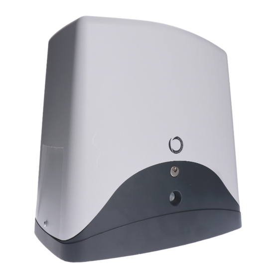
TURBO 250
MANUALE ISTRUZIONI
IT
INSTRUCTION MANUAL
GB
MANUEL D'EMPLOI
F
BEDIENUNGSANLEITUNG
D
MANUAL DE INSTRUCCIONES
E
MANUAL DE INSTRUÇÕES
P
Keyautomation
S.p.A
Chapitres
Table des Matières

Manuels Connexes pour Key Automation TURBO 250


Sommaire des Matières pour Key Automation TURBO 250
- Page 1 Motoriduttori per scorrevoli Gear-motor for sliding gates Motoreducteur pour coulissants Getriebe für Schiebegitter Motorreductores para rejas correderas Motorredutores para portões de correr TURBO 250 MANUALE ISTRUZIONI INSTRUCTION MANUAL MANUEL D'EMPLOI BEDIENUNGSANLEITUNG MANUAL DE INSTRUCCIONES MANUAL DE INSTRUÇÕES Keyautomation S.p.A...
- Page 11 NOTE ANMERKUNGEN NOTES NOTA NOTES OBSERVAÇÕES...
- Page 21 NOTE ANMERKUNGEN NOTES NOTA NOTES OBSERVAÇÕES...
- Page 22 SOMMAIRE SÉCURITÉ OUTILS MODÈLES ET CARACTÉRISTIQUES CARACTÉRISTIQUES TECHNIQUES DIMENSIONS D’ENCOMBREMENT TABLEAU D’ENSEMBLE CONTRÔLES PRÉLIMINAIRES INSTALLATION FIXATION DU MOTORÉDUCTEUR FIXATION DE LA CRÉMAILLÈRE FIXATION DU FIN DE COURSE MAINTENANCE RECOMMANDATIONS FINALES CE MANUEL EST EXCLUSIVEMENT DESTINÉ À L’INSTALLATEUR L’installation ne devra être effectuée que par du personnel professionnellement qualifié et con- formément aux dispositions des normes en vigueur.
-
Page 23: Normes De Sécurité
SÉCURITÉ Nous vous félicitons de votre choix et de la préférence accordée à nos produits. Ce manuel est rédigé dans le but de vous aider pour l’installation du motoréducteur. La lecture du manuel vous fournira des explications non seulement sur les fonctions du motoré- ducteur, mais aussi sur les normes de sécurité... -
Page 24: Modèles Et Caractéristiques
MODÈLES ET CARACTÉRISTIQUES CODICE DESCRIZIONE 900SC-200CS Motoréducteur électromécanique irréversible, 230 Vac 2500 kg. Pour portes coulissantes dotées de centrale, avec fin de course magnétique et prédisposition pour équipement radio. 900SC-240 Motoréducteur électromécanique irréversible, 400 Vac 2500 kg. Pour portes coulissantes, sans centrale, avec fin de course magnétique. -
Page 25: Tableau D'ensemble
TABLEAU D’ENSEMBLE 1 Motoréducteur 2 Feu clignotant 3 Antenne 4 Sélecteur à clé 5 Photocellule 6 Colonne 7 Crémaillère 8 Fin de course 9 Panneau de sécurité 10 Butées d’arrêt CONTRÔLES PRÉLIMINAIRES Avant de commencer l’installation, nous vous conseillons d’effectuer les contrôles et les opérations indiqués ci-dessous : 1_La porte doit posséder une structure robuste et appropriée. -
Page 26: Fonctionnement Manuel
FONCTIONNEMENT MANUEL 1 serrure Fig. 3 2 clés de déverrouillage 1. Insérer la clé fournie en dotation dans la serrure (1) et la tourner de 90° dans le sens contraire des aiguilles d’une montre (fig.3) 2. Insérer la clé de déblocage (2) et la tourner dans le sens des aiguilles d’une montre jusqu’au complet déblocage du pignon (fig.3). -
Page 27: Fixation Du Motoréducteur
FIXATION DU MOTORÉDUCTEUR Ouvrir l’emballage et contrôler le bon état de tous les composants de l’automatisme. • Retirer le couvercle en dévissant les vis (voir fig.5). • Placer le motoréducteur sur la plaque. • Insérer les 4 rondelles + écrous-frein pour fixer le moteur (fig. 6). •... -
Page 28: Fixation De La Crémaillère
FIXATION DE LA CRÉMAILLÈRE Modèle Fig. 7 Pour bien installer la crémaillère, débloquer le motoréducteur comme indiqué (fig. 3) et ouvrir com- plètement la porte. Placer un élément de crémaillère sur le pignon, puis le fixer à la porte à l’aide des vis et des ron- delles d’épaisseur. -
Page 29: Fixation Du Fin De Course
FIXATION DU FIN DE COURSE Fig. 9 La porte doit être équipée de butées d’arrêt en ouverture et en fermeture afin d’empêcher tout éventuel déraillement. La position de la butée d’arrêt doit garantir que les étriers de fin de course ne puissent entrer en collision avec le pignon. -
Page 30: Maintenance
MAINTENANCE DANGER : Avant d’effectuer toute opération de maintenance, toujours couper l’alimentation électrique. Le motoréducteur fourni est à graissage permanent et ne nécessite donc d’aucune mainte- nance. Pour effectuer une bonne maintenance de l’installation équipée du motoréducteur, procéder comme suit : •... - Page 31 NOTE ANMERKUNGEN NOTES NOTA NOTES OBSERVAÇÕES...
- Page 41 NOTE ANMERKUNGEN NOTES NOTA NOTES OBSERVAÇÕES...
- Page 51 NOTE ANMERKUNGEN NOTES NOTA NOTES OBSERVAÇÕES...
- Page 61 NOTE ANMERKUNGEN NOTES NOTA NOTES OBSERVAÇÕES...