Table des Matières
Publicité
Les langues disponibles
Les langues disponibles
Liens rapides
PELLETOFEN - POÊLES À GRANULÉS - PELLET ESTUFA
Il presente manuale è parte integrante del prodotto.
Si raccomanda di leggere attentamente le istruzioni prima
dell'installazione, manutenzione o utilizzo del prodotto.
This manual is an integral part of the product.
Read the instructions carefully before installing, servicing or
operating the product.
Die vorliegende Anleitung ist fester Bestandteil des Produkts.
Vor der Installation, Wartung und Verwendung die Anleitungen
stets aufmerksam durchlesen.
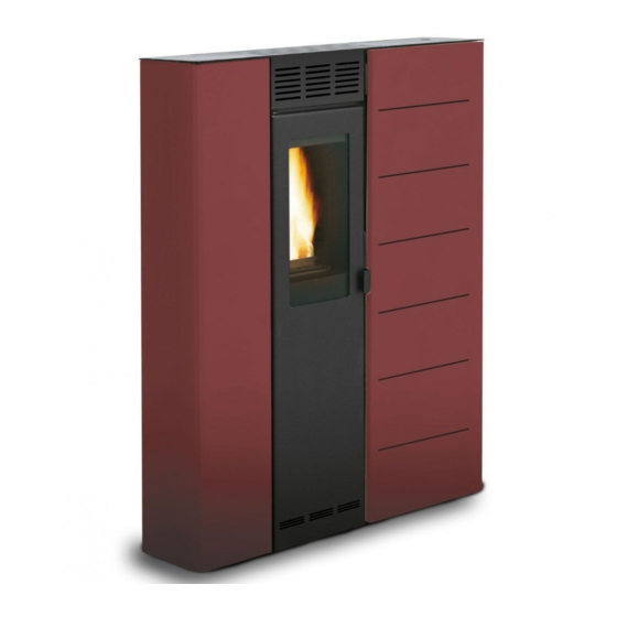
ECOFIRE
VIOLETTA
-
STUFE A PELLET
®
PELLET STOVES
Le présent manuel fait partie intégrante du produit.
Il est conseillé de lire attentivement les consignes
avant l'installation, l'entretien ou l'utilisation du produit.
Este
manual
es
parte
Se recomienda leer detenidamente las instrucciones antes
de la instalación, el mantenimiento y el uso del producto..
integrante
del
producto.
Publicité
Chapitres
Table des Matières

Manuels Connexes pour Palazzetti ECOFIRE VIOLETTA


Sommaire des Matières pour Palazzetti ECOFIRE VIOLETTA
- Page 1 ® ECOFIRE VIOLETTA STUFE A PELLET PELLET STOVES PELLETOFEN - POÊLES À GRANULÉS - PELLET ESTUFA Il presente manuale è parte integrante del prodotto. Si raccomanda di leggere attentamente le istruzioni prima dell’installazione, manutenzione o utilizzo del prodotto. Le présent manuel fait partie intégrante du produit. This manual is an integral part of the product.
- Page 2 Gentile cliente, desideriamo innanzitutto ringraziarLa per la preferenza che ha voluto accordarci acquistando il nostro prodotto e ci congratuliamo con Lei per la scelta. Per consentirLe di utilizzare al meglio la Sua nuova stufa, la invitiamo a seguire attentamente quanto descritto nel presente manuale. Dear Customer, We’d like to thank you for having purchased one of our products and congratulate you on your choice.
- Page 3 DIMENSIONI - DIMENSIONS - DIMENSIONS - ABMESSUNGEN - DIMENSIONES VIOLETTA Dimensioni (mm) Dimensions (mm) Abmessungen (mm) Dimensions (mm) Dimensiones (mm)
- Page 4 SCHEMA ELETTRICO - WIRING DIAGRAM - ELEKTRISCHER SCHALTPLAN ALIMENTAZIONE ALIMENTAZIONE 230VAC 230VAC ENCODER FUMI ITALIANO ENGLISH FRANCAIS DEUTSCH ESPAÑOL RESISTENZA AD IGNITER RESISTANCE GLUTWIDERSTAND RESISTENCIA INCANDESCENZA DOSATORE SYSTEME FEEDING SYSTEM SPENDER DOSADOR CARICAMENTO D’ALIMENTATION VENTILATORE VENTILATEUR VENTILADOR DE ROOM FAN * RAUMLUFTGEBLAESE* AMBIENTE* AMBIANT*...
- Page 5 DATI TECNICI - TECHNICAL SPECIFICATIONS - DONNÉES TECHNIQUES TECHNISCHE DATEN - DATOS TÉCNICOS VIOLETTA Ridotta Nominale reduced/verringerte/reduite/reducida nominal/Nwl/nominal/nominal Potenza termica globale (resa) 2408 kcal/h 6320 kcal/h 2,8 kW 7,35 kW Total Thermal power (yield) / Puissance thermique globale (rendement) Rendimento 91,91% Temperatura fumi 78°C...
-
Page 7: Table Des Matières
INDICE PREMESSA GENERALE FUNZIONI DISPONIBILI SIMBOLOGIA 10.1 FUNZIONE TIMER DESTINAZIONE D’USO 10.2 FUNZIONE STAND-BY SCOPO E CONTENUTO DEL MANUALE 10.3 FUNZIONE ANTIGELO CONSERVAZIONE DEL MANUALE 10.4 FUNZIONE RISPARMIO “ECONOMY” 10.5 RIACCENSIONE DOPO IL BLACK-OUT AGGIORNAMENTO DEL MANUALE 10.6 LETTURA ORE DI FUNZIONAMENTO GENERALITÀ... -
Page 8: Premessa Generale
La stufa funziona unicamente con la porta del l’installazione della stufa non può essere considerata focolare chiusa. a carico della PALAZZETTI, essa è, e rimane, a carico dell’installatore, al quale è demandata Non si deve mai aprire la portina durante il l’esecuzione delle verifiche relative alla canna... -
Page 9: Principali Norme Rispettate Eda Rispettare
1.9 RESPONSABILITÀ DEL manuali di istruzione; COSTRUTTORE telecomando (solo nei modelli dove previsto); Con la consegna del presente manuale PALAZZETTI attrezzo per apertura della portina del focolare declina ogni responsabilità, sia civile che penale, (solo nei modelli dove previsto). diretta o indiretta, dovuta a: vigenti nel paese ed alle direttive di sicurezza;... -
Page 10: Avvertenze Per La Sicurezza
2 AVVERTENZE PER LA 2.3 AVVERTENZE PER L’UTILIZZATORE Predisporre il luogo d’installazione della stufa SICUREZZA secondo i regolamenti locali, nazionale ed europei. 2.1 AVVERTENZE PER L’INSTALLATORE calde. Per questo motivo si raccomanda la Osservare le prescrizioni indicate nel presente massima cautela durante il funzionamento in particolare: manuale. -
Page 11: Caratteristiche Del Combustibile
3 CARATTERISTICHE DEL COMBUSTIBILE 3.1 CARATTERISTICHE DEL COMBUSTIBILE Il pellet (fig. 3.1) è un composto costituito da varie tipologie di legno pressato con procedimenti meccanici nel rispetto delle normative a tutela dell’ambiente, è l’unico combustibile previsto per questo tipo di stufa. possono variare in relazione al tipo ed alla qualità... -
Page 12: Descrizione Delle Parti Principali Della Stufa
5 DESCRIZIONE DELLE PARTI PRINCIPALI DELLA STUFA A) Serbatoio pellet B) Porta con maniglia C) Camera di combustione D) Cassetto cenere E) Pannello comandi F) Braciere G) Ventilatore espulsione fumi C o n s e n t e l ’ e s p u l s i o n e f o r z a t a d e i f u m i e contemporaneamente l’aspirazione di aria comburente al braciere. -
Page 13: Considerazioni Generali
6 INSTALLAZIONE 6.3 LUOGO DI INSTALLAZIONE DELLA STUFA 6.1 CONSIDERAZIONI GENERALI che devono essere rispettate nel posizionamento Nei paragrafi successivi sono riportate alcune della stufa rispetto a materiali e oggetti combustibili. indicazioni da rispettare per ottenere il massimo A) Parete adiacente. rendimento del prodotto acquistato. -
Page 14: Aria Comburente
6.4 ARIA COMBURENTE La stufa, durante il suo funzionamento, preleva una quantità di aria dall’ambiente in cui è collocata (ad eccezione dei prodotti della serie ermetica che possono prelevarla direttamente dall’esterno); quest’aria dovrà essere reintegrata attraverso una Se la parete posteriore della stufa è una parete esterna, realizzare un foro per l’aspirazione dell’aria comburente ad una altezza dal suolo di circa 20-30 cm rispettando le indicazioni dimensionali riportate... -
Page 15: Scarico Fumi
E’ possibile, in alternativa, collegare l’ingresso dell’aria comburente della stufa alla presa d’aria 6.5 SCARICO FUMI La stufa funziona con la camera di combustione in depressione è pertanto indispensabile assicurarsi che lo scarico dei fumi sia a tenuta. La stufa deve essere collegata ad un proprio sistema di evacuazione fumi esclusivo, ed idoneo ad assicurare una adeguata dispersione in atmosfera dei prodotti della combustione. - Page 16 6.5.1 Scarico a tetto mediante camino tradizionale Il camino per lo scarico dei fumi deve essere realizzato in osservanza alle norme UNI 10683- EN 1856-1-2- EN 1857- EN 1443- EN 13384-1-3- EN 12391-1 sia per quanto riguarda le dimensioni che per i materiali utilizzati nella sua costruzione. Camini FATISCENTI, realizzati con materiale non e pregiudicano il buon funzionamento della stufa.
-
Page 17: Livellamento Della Stufa
6.6 LIVELLAMENTO DELLA STUFA La stufa deve essere livellata, con l’ausilio di un’asta a bolla, agendo sui piedini di regolazione (Fig. 6.1). A B = Asta a Bolla. E’ possibile ancorare la stufa ad un muro (di materiale ignifugo), aprendo i due pannelli laterali della stufa e fissando due viti con tassello in corrispondenza dei punti indicati in Fig. -
Page 18: Collegamento Ad Un Impianto Di Distribuzione Dell'aria
6.8 COLLEGAMENTO AD UN IMPIANTO DI DISTRIBUZIONE DELL’ARIA (solo per i modelli canalizzabili o provvisti di kit di canalizzazione) E’ possibile collegare i modelli ad aria canalizzabili ad un condotto di distribuzione del calore. Si consiglia di utilizzare preferibilmente condotti a sezione circolare con interno liscio e adeguatamente isolati per evitare dispersioni di calore. -
Page 19: Funzionamento
7 FUNZIONAMENTO 7.1 PANNELLO COMANDI Il pannello (Fig.7.1) è costituito dal display LCD retroilluminato, dal tasto di accensione , dal tasto di spegnimento e dai due tasti menù ( Il pannello permette: e manutenzione. Il display visualizza tre stati della stufa: 1) SPENTO segnala che la stufa non è... -
Page 20: Accesso Ai Menu
Quando la temperatura ambiente sarà effettivamente uguale a quella impostata, la stufa si autoregolerà per mantenere la temperatura consumando il meno possibile, ed il display visualizzerà: MENU COMPRESSO MENU ROTANTE MENU EASY P r i m a r i g a : “ M O D U L A temperature visualizzate LAVORO”... -
Page 21: Operazioni Preliminari
8 OPERAZIONI PRELIMINARI 8.1 CARICAMENTO PELLET La prima operazione da eseguire prima di accendere il prodotto è quella di riempire il serbatoio di combustibile (pellet). Il pellet deve essere versato nel serbatoio con una paletta. Non svuotare il sacco direttamente nel serbatoio per evitare di caricare della segatura o altri elementi estranei che potrebbero compromettere il buon funzionamento della stufa e per evitare di... -
Page 22: Utilizzo Della Stufa
9 UTILIZZO DELLA STUFA quando non ci si trova nella fase “LAVORO” è necessario accedere al “MENU SET LAVORO” come illustrato al paragrafo 11.1. 9.1 ACCENSIONE I valori impostati verranno mantenuti fino alla Per accendere la stufa tenere premuto il tasto successiva variazione, anche a stufa spenta o per qualche secondo. -
Page 23: Funzioni Disponibili
10 FUNZIONI DISPONIBILI 10.1 FUNZIONE TIMER Con questa funzione è possibile impostare i Spostandosi sulla seconda riga (tasto programmi personalizzati per l’accensione e/o lo troviamo i giorni della settimana (L,...,D) da abbinare spegnimento automatico della stufa. al programma. Spostarsi con il tasto tra i giorni e abilitare quelli Portarsi nel “MENU TIMER”... - Page 24 ESEMPI: Esempio 1 Fig.10.2). 2) Premere 3) Premere il tasto ) per scegliere 5) Premere il tasto o il tasto per scorrere le Fig.10.2 freccia. ci porteremo ci porteremo ci porteremo Fig.10.3 Esempio 2 Fig.10.4 Esempio 3 sola). Fig.10.5...
-
Page 25: Funzione Stand-By
10.2 FUNZIONE STAND-BY In fase di lavoro (cioè quando la stufa è accesa e a regime) consente di spegnere la stufa al raggiungimento della temperatura ambiente impostata (SET T. AMB.) e riavviarla al raggiungimento della temperatura ambiente minima impostata (TEMP. START). Per abilitare tale funzione portarsi nel “MENU SET STUFA”... -
Page 26: Descrizione Dei Menu
11 DESCRIZIONE DEI MENU In questo capitolo vengono illustrati i contenuti dei menù della stufa, ai quali è possibile accedere attraverso la procedura descritta nel paragrafo . 11.1 MENU SET LAVORO Attraverso questo menù si imposta e si regola il funzionamento della stufa, visualizzando contemporaneamente tutti i parametri di lavoro. - Page 27 Scorrere con i tasti i sottomenu Selezionare con il tasto quello al quale si vuole accedere Spostarsi tra i vari parametri con il tasto (quello selezionato lampeggerà) (“ok”) Premere il tasto (“x”) per uscire dal sottomenu (ripremerlo eventualmente per uscire dai menu superiori). Le funzioni “STAND-BY”...
-
Page 28: Gestione Degli Allarmi
Eseguire la Procedura standard “Ripristino degli allarmi” sopra descritta. Se l’allarme persiste controllare che la stufa o la canna fumaria abbiano bisogno di manutenzione. assistenza tecnica Palazzetti. Fig. 12.1 nuova accensione è obbligatorio che questa venga effettuata dal pannello comandi. -
Page 29: Canalizzazione Dell'aria
13 CANALIZZAZIONE DELL’ARIA SOLO PER I MODELLI CANALIZZABILI O PROVVISTI DI KIT DI CANALIZZAZIONE Le stufe canalizzabili o dotate di kit di canalizzazione da deviare l’aria calda su due canalizzazioni diverse. Una è quella di riscaldamento della stanza in cui è posizionata la stufa Fig. -
Page 30: Manutenzione
14 MANUTENZIONE 14.1 PRECAUZIONI DI SICUREZZA Prima di effettuare qualsiasi operazione di manutenzione adottare le seguenti precauzioni: Assicurarsi che tutte le parti della stufa siano fredde. Accertarsi che le ceneri siano completamente spente. Utilizzare i dispositivi di protezione individuale previsti dalla direttiva 89/391/CEE. Accertarsi che l’interruttore generale di linea sia disinserito. - Page 31 14.3.3 Pulizia del cassetto cenere La pulizia del cassetto cenere va eseguita ogni settimana o quando necessario. Per accedere al cassetto cenere, aprire la porta cassetto cenere ed estrarre il cassetto (Fig.14.2). Svuotare il cassetto. Aspirare le eventuali ceneri residue dal vano che ospita il cassetto cenere. Reinserire e richiudere il cassetto.
-
Page 32: Manutenzione Straordinaria
Centro di Assistenza Tecnica Autorizzato della Palazzetti una volta all’anno e preferibilmente a inizio stagione. Questa manutenzione ha lo scopo di accertare ed Se sul pannello di controllo compare la scritta MANUTENZIONE STRAORDINARIA si dovrà... -
Page 33: Demolizione Esmaltimento
15 DEMOLIZIONE E SMALTIMENTO La demolizione e lo smaltimento della stufa sono ad esclusivo carico e responsabilità del proprietario che dovrà agire in osservanza delle leggi vigenti nel proprio Paese in materia di sicurezza, rispetto e tutela dell’ambiente. Smantellamento e smaltimento possono essere ditte autorizzate al recupero ed all’eliminazione dei materiali in questione. - Page 35 INDEX INTRODUCTION FUNCTIONS AVAILABLE 10.1 TIMER FUNCTION SYMBOLS 10.2 STANDBY FUNCTION INTENDED USE 10.3 FROST PROTECTION FUNCTION PURPOSE AND CONTENTS OF THIS MANUAL 10.4 “ECONOMY” FUNCTION HOW TO KEEP THIS MANUAL 10.5 RESTARTING AFTER A POWER FAILURE UPDATES TO THE MANUAL 10.6 READING THE OPERATING HOURS GENERAL INFORMATION...
-
Page 36: Introduction
If required, an additional copy can be ordered from explanations. PALAZZETTI. PALAZZETTI reserves the right to modify the ALE OF THE STOVE If the stove is sold the user must also provide the stove at any time, without prior notice. -
Page 37: Main Reference Standards
EEC”. E) Directive 85/374/EEC: “Approximation of 1.11 TECHNICAL SERVICE the laws, regulations and administrative PALAZZETTI has an extensive network of service provisions of the Member States concerning centres staffed by specialists trained directly by liability for defective products.” the company. -
Page 38: Safety Warnings
2 SAFETY WARNINGS 2.3 WARNINGS FOR THE USER Prepare the stove installation site in accordance 2.1 INSTALLATION WARNINGS with local, national and European regulations. As the stove is a heating appliance it has very manual. hot outside surfaces. For this reason maximum The stove assembly and dismantling instructions are reserved exclusively for specialist technicians. -
Page 39: Fuel Specifications
3 FUEL SPECIFICATIONS 3.1 FUEL SPECIFICATIONS Pellets (Fig. 3.1) are made from various types of mechanically compacted wood in compliance with environmental protection standards. Pellets are the only fuel that can be used on this type of stove. vary in relation to the type and quality of pellets used. -
Page 40: Description Of The Stove's Main Parts
5 DESCRIPTION OF THE STOVE’S MAIN PARTS A) Pellet storage box B) Door with handle C) Combustion chamber D) Ash box E) Control panel F) Hearth G) Smoke expulsion fan It allows the forced expulsion of smoke and the simultaneous intake of air for combustion to the hearth. -
Page 41: Installation
6 INSTALLATION 6.3 STOVE INSTALLATION SITE Figure 5.2 shows the minimum clearance there should be 6.1 GENERAL INFORMATION objects. The following paragraphs provide instructions that Adjacent wall. must be complied with in order to ensure maximum Rear wall. Side wall. Floor protection. -
Page 42: Combustion Air
6.4 COMBUSTION AIR During operation the stove takes in a certain amount of air from the room where it’s installed (except for the “Ermetica” series products that can take in air directly from the outside); this air must be replaced through an opening to the outside from the room (Fig. -
Page 43: Flue Gas Exhaust
It’s possible, alternatively, connect the stove combustion air intake to the fresh air opening using a special pipe (Fig. 5.6). 6.5 FLUE GAS EXHAUST The stove operates with negative pressure in the gas discharge must be airtight. The stove must be connected to its own ensuring adequate atmospheric dispersion of the combustion byproducts. - Page 44 6.5.1 Discharge through roof using a traditional chimney be made in accordance with standards UNI 10683 - EN 1856-1-2 - EN 1857 - EN 1443 - EN 13384- 1-3 - EN 12391-1 both as regards the dimensions and the construction materials used. DAMAGED chimneys made from unsuitable material (asbestos cement, galvanised steel, etc..
-
Page 45: Levelling The Stove
6.6 LEVELLING THE STOVE The stove must be levelled by turning the adjustment feet (Fig. 6.1), with the aid of a spirit level. A B = Spirit Level. It is possible to fasten the stove to the wall - made of in Fig. -
Page 46: Connection To An Air Distribution System
6.8 CONNECTION TO AN AIR DISTRIBUTION SYSTEM (only for ducted models or provided with ducting kit) Ducted models can be connected to a hot air distribution system. The pipes used should preferably be circular with a smooth inner surface and suitably insulated to avoid heat loss. -
Page 47: Stove Description
7 STOVE DESCRIPTION 7.1 CONTROL PANEL The panel (Fig.7.1) consists of a backlit LCD display, the on button , off button and two menu buttons ( The panel is used to: start and switch off the stove; adjust operation; set the management and maintenance programs. -
Page 48: Accessing The Menus
COMPRESSED MENU SCROLLING MENU EASY MENU T h e t w o t e m p e r a t u r e s First row: “MODULATION” displayed (room and set) will Second row: in addition to the stove operating parameters, the message “THERMOSTAT ON”... -
Page 49: Preliminary Operations
8 PRELIMINARY OPERATIONS 8.1 LOADING THE PELLETS The pellets are loaded into in the hopper using a scoop. Do not empty the sack directly into the hopper so as to avoid loading sawdust or other foreign bodies that may affect proper stove operation and avoid spilling pellets outside of the hopper. -
Page 50: Stove Operation
9 STOVE OPERATION even when the stove is switched off or unplugged from the power supply. 9.1 STARTING THE STOVE To start the stove hold the * button for several EASY MENU seconds. The display shows the message “AWAITING room temperature using the up and down buttons. FLAME”. -
Page 51: Functions Available
10 FUNCTIONS AVAILABLE Use the button to scroll the days and enable 10.1 TIMER FUNCTION each day as desired using either of the two arrow This function is used to set custom programs for buttons. An icon representing a solid dot “ ” will automatically starting and/or switching off the stove. - Page 52 EXAMPLES: Example 1 1) Press the buttons together; the display will show: OPERATING SETTINGS MENU (Fig.10.2). 2) Press and move to: TIMER MENU. 3) Press to select this menu. 4) Use the arrow buttons ( ) *) to choose the desired program (e.g. “P2”) and select this by pressing Fig.10.2 5) Press the...
-
Page 53: Standby Function
10.2 STANDBY FUNCTION During operation (i.e. when the stove is on and in steady operating conditions) the stove can be switched off when reaching the set room temperature (SET ROOM T.) and start again when reaching the set minimum room temperature (START TEMP.). -
Page 54: Menus
11 MENUS This chapter illustrates the contents of the menus on the stove’s display, accessed using the procedure described. 11.1 OPERATING SETTINGS MENU This menu is used to set and adjust stove operation, and displays all the operating parameters. Access the “OPERATING SETTINGS MENU” following the “Procedure for accessing the menus” . The display will show parameters “P”... - Page 55 4) Scroll the submenus using the button 5) Use the button to select the desired submenu 6) Scroll the various parameters using the 7) Modify the value using the button (“ok”) 9) Press (“x”) to exit the submenu (press the same button again if necessary to go back another menu level).
-
Page 56: Alarm Management
Press the button on the thermostat to reset the stove, Fig.12.1. Perform the standard procedure, “Reset alarms”, as described above. If the alarm occurs twice consecutively, immediately contact a Palazzetti service centre. If the external thermostat is being used and an alarm is activated, the stove can only be started again from the control panel. -
Page 57: Air Ducts
13 AIR DUCTS ONLY FOR DUCTED MODELS OR PROVIDED WITH DUCTING KIT different outlets. One is for heating the room where the stove is installed, Fig. 13 (A) through the front or top grills (according to the model). The other is used to heat other rooms away from the stove, Fig.13 (B), through a system of air ducts. -
Page 58: Maintenance And Cleaning
14 MAINTENANCE AND CLEANING 14.1 SAFETY PRECAUTIONS Prior to embarking on any maintenance work the following precautions must be taken: A) Make sure all parts of the stove are cold. B) Make sure the ashes are completely cold and not burning. - Page 59 14.2.2 Cleaning the ash box The ash bin should be cleaned every week or whenever necessary. To access the ash bin, open the ash bin door and remove the bin (Fig.14.2) using the tool provided. Empty the bin. Vacuum any residual ash from the compartment that houses the ash bin.
-
Page 60: Extraordinary Maintenance
14.3 EXTRAORDINARY MAINTENANCE The stove is a heat generator that uses solid fuel and therefore requires annual extraordinary maintenance that has to be done by an authorised Royal Technical Assistance Centre either once a year or preferably at the beginning of the season. The reason for this maintenance is to ascertain and We recommend drawing up an annual maintenance contract for the product with the Authorised... -
Page 61: Information For Demolition And Disposal
15 INFORMATION FOR DEMOLITION AND DISPOSAL Demolition and disposal is the sole responsibility of the owner who must comply with the relative laws in force in his country on the matter of safety and safeguarding the environment. Dismantling and disposal may be entrusted to a third party provided we are talking about a company authorised to salvage and eliminate said materials. - Page 63 INHALT ALLGEMEINES VORWORT VERFÜGBARE FUNKTIONEN VERWENDETE SYMBOLE 10.1 TIMER-FUNKTION ZWECKBESTIMMUNG 10.2 STANDBY-FUNKTION ZWECK UND INHALT DES HANDBUCHS 10.3 FROSTSCHUTZFUNKTION AUFBEWAHRUNG DES HANDBUCHS 10.4 SPARFUNKTION “ECONOMY” AKTUALISIERUNG DES HANDBUCHS 10.5 WIEDEREINSCHALTEN NACH STROMAUSFALL ALLGEMEINES 10.6 LESEN DER BETRIEBSSTUNDEN WICHTIGSTE BEFOLGTE UND ZU BEFOLGENDE 10.7 EIN- UND AUSSCHALTEN MIT RAUMREGLER (Nur für NORMEN...
-
Page 64: Allgemeines Vorwort
Der Ofen darf nicht bedient werden, wenn nicht alle ESCHÄDIGUNG ODER ERLUST im Handbuch enthaltenen Angaben verstanden Im Bedarfsfall kann bei der Firma PALAZZETTI eine wurden; bitten Sie im Zweifelsfall immer um Rat oder Kopie angefordert werden. fordern Sie den Eingriff von Fachpersonal der Firma ERÄUSSERUNG DES... -
Page 65: Wichtigste Befolgte Und Zu Befolgende Normen
Im Ofen liegt das folgende Material bei: wird jede sowohl zivil- als auch strafrechtliche, Bedienungsanleitungen; mittelbare oder unmittelbare Haftung der Firma Fernbedienung (sofern vorgesehen); PALAZZETTI für die folgenden Fälle ausgeschlossen: Werkzeug zum Öffnen der Feuerraumtür Installation Abweichung (sofern vorgesehen). Installationsland geltenden Bestimmungen und von den Sicherheitsvorschriften;... -
Page 66: Sicherheitshinweise
2 SICHERHEITSHINWEISE Teilen oder Steckverbindern die Spannungszufuhr unterbrechen. 2.3 HINWEISE FÜR DEN BENUTZER 2.1 HINWEISE FÜR DEN INSTALLATIONSTECHNIKER den lokalen, nationalen und europäischen Bestim- Die in diesem Handbuch enthaltenen Vorschriften mungen vor. sind strikt zu befolgen. Da der Ofen als Heizgerät dient, werden seine Au- Die Montage- und Demontageanleitungen des Ofens sind ausschließlich den Fachtechnikern vorbehalten. -
Page 67: Brennstoff-Eigenschaften
Während des Betriebs dürfen die lackierten Teile nicht berührt werden, um eine Beschädigung der Lackierung zu vermeiden. 3 BRENNSTOFF- EIGENSCHAFTEN 3.1 BRENNSTOFFEIGENSCHAFTEN Holzpellets (Abb. 3.1) sind der einzige für diesen Ofentyp vorgesehene und zulässige Brennstoff und bestehen aus verschiedenen Arten von Holz, das unter Befolgung der Umweltschutzbestimmungen mechanisch gepresst wird. -
Page 68: Beschreibung Der Hauptbestandteile Des Heizofens
5 BESCHREIBUNG DER HAUPTBESTANDTEILE DES HEIZOFENS A) Pellets-Behälter B) Tür mit Griff C) Feuerraum D) Aschenkasten E) Bedienblende F) Feuerbecken G) Rauchabsauggebläse Ermöglicht die forcierte Rauchableitung und gleichzeitig die Ansaugung von Verbrennungsluft ins Feuerbecken. Arbeitet parallel zur Beschickungsschnecke und regelt den Rauchabzug je nach Wärmeleistung. H) Beschickungssystem Bestehend aus einem Getriebemotor und einer Schnecke - ermöglich das Dosieren der Pellets im... -
Page 69: Installation
6 INSTALLATION 6.3 AUFSTELLUNGSORT DES OFENS In der Abbildung (Abb. 5.2) sind die Mindestabstände zu brennbaren Materialien oder Gegenständen angegeben, 6.1 ALLGEMEINES die bei der Aufstellung des Heizofens einzuhalten sind. Die nachstehenden Abschnitte enthalten einige A) Angrenzende Wand. Anleitungen, die befolgt werden müssen, um den B) Hintere Wand. -
Page 70: Verbrennungsluft
6.4 VERBRENNUNGSLUFT Während des Betriebs entnimmt der Ofen eine gewisse Menge Raumluft (mit Ausnahme der Produkte der raumluftunabhängigen Serie, die die Luft direkt von außen entnehmen können); diese Luftmenge dem muss dem Raum über einen Außenlufteinlass wieder zugeführt werden (Abb. 5.3). -
Page 71: Abgasführung
Es ist auch möglich, alternativ, den Eintritt der Verbrennungsluft des Ofens über eine Rohrleitung mit dem Lufteinlass verbinden (Abb. 5.6). 6.5 ABGASFÜHRUNG Der Ofen funktioniert mit Brennkammer in Unterdruck, daher ist unbedingt sicherzustellen, dass der Rauchabzug dicht ist. Ofen muss einem eigenen ausschließlichen Rauchabzugssystem verbunden... - Page 72 6.5.1 Abführung über das dach mit traditionellem schornstein Der Schornstein für den Rauchabzug muss sowohl hinsichtlich der Maße als auch in Bezug auf das Baumaterial gemäß den Normen UNI 10683- EN 1856-1-2- EN 1857- EN 1443- EN 13384-1-3- EN 12391-1 ausgeführt werden. BAUFÄLLIGE, mit ungeeignetem Material (Asbestzement, verzinkter Stahl usw.
-
Page 73: Nivellieren Des Heizofens
6.6 NIVELLIEREN DES HEIZOFENS Der Heizofen muss unter Einsatz einer Wasserwaage anhand der Stellfüße nivelliert werden (Fig. 6.1). A B = Wasserwaage. Der Ofen kann an der Wand (aus feuerbeständiges Material) verankert werden. Um diesen anzuschrauben, müssen die zwei seitliche Verkleidungselemente (Paragraf 8.3) geöffnet werden und zwei Schrauben mit Dübel genau in den Punkten wie in der Abb. -
Page 74: Anschluss An Ein Luftleitsystem
6.8 ANSCHLUSS AN EIN LUFTLEITSYSTEM (nur für kanalisierbare Modelle bzw. Modelle mit Kanalisierungsset) Die kanalisierbaren luftgeführten Modelle können an ein Wärmeverteilsystem angeschlossen werden. Wir empfehlen, vorzugsweise Rohrleitungen mit rundem Querschnitt und glatter Innenwand zu verwenden, die angemessen isoliert werden müssen, um Wärmeverluste zu vermeiden. -
Page 75: Beschreibung Des Ofens
7 BESCHREIBUNG DES OFENS 7.1 BEDIENPANEL Das Bedienpanel (Abb.7.1) besteht aus dem hinterleuchteten LDC-Display, der Einschalttaste , der Ausschalttaste und den zwei Menütasten Am Bedienpanel können folgende Vorgänge gesteuert werden: Ofen ein- und ausschalten; Betrieb regeln; Betriebs- und Wartungsprogramme einrichten. Am Display werden drei Betriebszustände des Ofens angezeigt: 1) AUS: zeigt an, dass der Ofen nicht in Betrieb... -
Page 76: Öffnen Der Menüs
wie möglich verbraucht wird. Auf dem Display erscheint: KOMPRIMIERTES MENÜ ROTIERENDES MENÜ MENU EASY Das Blinken der zwei angezeigten Erste Zeile: “MODULATION Temperaturen (Raumtemperatur BETRIEB” und eingestellte Temperatur) Zweite Zeile: Zusätzlich zu den Betriebsparametern des Ofens erscheint zyklisch auch die Anzeige „THERMOSTAT ON“... -
Page 77: Vorbereitung
8 VORBEREITUNG 8.1 PELLETZUFÜHRUNG Bevor das Gerät eingeschaltet wird, muss als erstes der Brennstoffbehälter (Pellets) gefüllt werden. Die Pellets müssen mit einer Schaufel in den Behälter gefüllt werden. Schütten Sie die Pellets nicht direkt aus dem Sack in den Behälter, um nicht versehentlich Sägemehl oder andere Fremdkörper einzufüllen, die den einwandfreien Betrieb des Ofens beeinträchtigen könnten, und um keine Pellets außerhalb des... -
Page 78: Gebrauch Des Ofens
9 GEBRAUCH DES OFENS Nach Einstellung aller Parameter die Taste (“X”) drücken, um das Menü zu schließen. 9.1 EINSCHALTEN Um die Parameter des komprimierten Menüs zu bearbeiten, solange die Phase „BETRIEB“ nicht aktiv Zum Einschalten des Ofens die Taste ein paar ist, muss das “MENÜ... -
Page 79: Verfügbare Funktionen
10 VERFÜGBARE FUNKTIONEN Wenn als Ausschaltuhrzeit OFF eingestellt wird, 10.1 TIMER-FUNKTION wird die Ausschaltung deaktiviert. Diese Option ist nützlich, wenn nur die Einschaltung Programme für das automatische Ein- und/oder oder nur die Ausschaltung programmiert, und die Ausschalten des Ofens eingerichtet werden. andere Funktion ausgeschlossen werden soll. - Page 80 BEISPIELE: Beispiel 1 oder Fig.10.2 5) Die Taste oder die Taste durch Fig.10.3 Beispiel Fig.10.4 Beispiel 3 Fig.10.5...
-
Page 81: Standby-Funktion
10.2 STANDBY-FUNKTION Während des Betriebs (d.h. wenn der Ofen eingeschaltet und in Betrieb ist) gestattet diese Funktion, den Ofen bei Erreichen der eingestellten Raumtemperatur (SW RAUMT.) aus- und bei Erreichen der eingestellten Mindestraumtemperatur (TEMP. START) wieder einzuschalten. Um diese Funktion zu aktivieren, das „MENÜ OFENSOLLWERTE“ mit der Prozedur „Öffnen der Menüs“ öffnen und drücken . -
Page 82: Beschreibung Der Menüs
11 BESCHREIBUNG DER MENÜS In diesem Kapitel werden die Inhalte der Menüs des Ofens beschrieben, die wie beschrieben geöffnet werden. 11.1 MENÜ BETRIEBSSOLLWERTE Über dieses Menü wird der Ofenbetrieb eingestellt und geregelt und gleichzeitig alle Betriebsparameter angezeigt. Das „MENÜ BETRIEBSSOLLWERTE“ mit der in beschriebenen Prozedur „Öffnen der Menüs“ öffnen. Auf dem Display werden die Parameter „P“... - Page 83 Mit den Tasten bzw. durch die Untermenüs blättern Mit der Taste wählen, welches geöffnet werden soll. Den Cursor mit der Taste von einem Parameter zum nächsten bewegen (der jeweils ausgewählte blinkt) Den Wert mit den Tasten oder ändern. Die Änderung mit der Taste (“ok”) bestätigen.
-
Page 84: Verwaltung Der Alarmmeldungen
Wenn der Alarm fortdauert, kontrollieren, ob der Ofen oder das Schornsteinrohr gewartet werden müssen. Sollte der Alarm zwei Mal hintereinander auftreten, wenden Sie sich bitte sofort an den technischen Kundendienst von Palazzetti. Fig. 12.1 Wenn ein Außenthermostat verwendet wird und irgendein Alarm auftritt, ist ein Neustart des... -
Page 85: Luftkanalisierung
13 LUFTKANALISIERUNG NUR FÜR KANALISIERBARE ODELLE BZW ODELLE MIT ANALISIERUNGSSET Die kanalisierbaren oder mit Kanalisierungsset ausgestatteten Öfen können so konfiguriert werden, dass die Warmluft zu zwei verschiedenen Kanalisierungen geleitet wird. E i n e i s t d i e K a n a l i s i e r u n g , m i t d e r d e r Aufstellungsraum des Ofens über die (je nach geheizt wird, siehe Abb. -
Page 86: Instandhaltung Und Reinigung
14 INSTANDHALTUNG UND REINIGUNG 14.1 VORBEUGENDE SICHERHEITSMASSNAHMEN Vor jedem Wartungseingriff unbedingt folgende Sicherheitsmaßnahmen treffen: A) Sicherstellen, dass alle Heizofenteile kalt sind. B) Sicherstellen, dass die Asche komplett erloschen ist. C) Die laut Richtlinie 89/391/EWG vorgesehenen individuellen Schutzvorrichtungen anwenden. D) Sicherstellen, dass der Hauptschalter ausgeschaltet ist. - Page 87 14.2.2 Reinigung der Aschenlade (Modelle mit Aschekasten) Die Reinigung des Aschekastens ist einmal wöchentlich oder bei Bedarf durchzuführen. Um den Aschekasten freizulegen, die Tür des Aschekastens öffnen und den Aschekasten mithilfe des mitgelieferten Werkzeugs herausziehen (Abb. 14.2). Den Aschekasten entleeren. Eventuell in der Aufnahme des Aschekastens verbliebene Ascherückstände entfernen.
-
Page 88: Ausserordentliche Wartung
14.3 AUSSERORDENTLICHE WARTUNG Der Heizofen ist ein Heizgenerator für die Beschickung mit festen Brennstoffen und benötigt dadurch eine jährliche außerordentliche Wartung, die am Besten am Anfang der Heizsaison von einer autorisierten Royal- Kundendienststelle durchgeführt werden sollte. Diese Wartung überprüft und gewährleistet die perfekte Leistungsfähigkeit aller eingesetzten Bestandteile. -
Page 89: Informationen Für Den Abriss Und Die Entsorgung
15 INFORMATIONEN FÜR DEN ABRISS UND DIE ENTSORGUNG Der Abriss und die Entsorgung des Heizofens geht ganz und gar zu Lasten des Eigentümers, der auch dafür verantwortlich ist und gemäß den gültigen Sicherheits- und Umweltschutzvorschriften des Aufstellungslands vorzugehen hat. Mit dem Abriss und der Entsorgung können auch Firmen beauftragt werden, die für die Sammlung und Entsorgung der betroffenen Materialien befugt sind. - Page 91 INDEX PRÉAMBULE FONCTIONS DISPONIBLES SYMBOLOGIE 10.1 FONCTION TIMER UTILISATION 10.2 FONCTION STAND-BY OBJECTIFS ET CONTENU DU MANUEL 10.3 FONCTION ANTIGEL ENTRETIEN DU MANUEL 10.4 FONCTION “ECONOMY” MISE A JOUR DU MANUEL 10.5 RALLUMAGE APRES UNE COUPURE DE COURANT GENERALITES PRINCIPALES NORMES DE SECURITE DE 10.6 LECTURE HEURES DE FONCTIONNEMENT REFERENCE A RESPECTER...
-
Page 92: Préambule
En cas de doute, demander toujours l’intervention d’un technicien 1.5 MISE A JOUR DU MANUEL agréé PALAZZETTI. Ce manuel est conforme aux connaissances PALAZZETTI se réserve le droit d’apporter toutes techniques disponibles moment modifications spécifiques et techniques et/ou commercialisation du poêle. -
Page 93: Principales Normes De Securite De Reference A Respecter
C) Directive 89/391/CEE: «Mise en œuvre de mesures visant à promouvoir l’amélioration 1.11 ASSISTANCE TECHNIQUE de la sécurité et la santé des travailleurs au Les services d’assistance PALAZZETTI sont en travail». mesure de résoudre tout problème inhérent à D) Règlement UE 305/2011 : l’utilisation et à... -
Page 94: Recommandations De Sécurité
Dans le cas où l’installateur serait défaillant, veuillez Observer les instructions reportées dans cette nous contacter pour l’intervention d’un autre notice. technicien agrée par PALAZZETTI. Observer les instructions reportées sur les La responsabilité de travailler sur le poêle est, et plaquettes appliquées sur le poêle. -
Page 95: Caracteristiques Du Combustible
3 CARACTERISTIQUES DU COMBUSTIBLE 3.1 CARACTERISTIQUES DU COMBUSTIBLE Les pellets (Fig. 3.1) proviennent des résidus de bois de différentes essences compressés mécaniquement dans respect l’environnement. C’est le seul combustible prévu pour ce type de poêle. peuvent varier en fonction du type et de la qualité des pellets utilisés. -
Page 96: Description Des Parties Principales Du Poêle
5 DESCRIPTION DES PARTIES PRINCIPALES DU POÊLE A) Réservoir à pellets B) Porte avec poignée C) Chambre de combustion D) Tiroir à cendres E) Panneau de commande F) Brasier G) Ventilateur d’expulsion des fumées Permet l’expulsion forcée des fumées et simultanément l’aspiration d’air de combustion destiné... -
Page 97: Installation
6 INSTALLATION 6.3 LIEU D’INSTALLATION DU POELE Sur la figure. 5.2 sont indiquées les dégagements minimum à respecter pour le positionnement du poêle 6.1 CONSIDERATIONS GENERALES Il y a plusieurs facteurs qui rendent une combustion A) Paroi adjacente. B) Paroi postérieure. et à... -
Page 98: Air De Combustion
porter le marquage CE. Pour le combustible bois doit être marqué G xx (G indique que le raccordement résiste au feu de cheminée et xx est la distance de sécurité minimum en millimètres). 6.4 AIR DE COMBUSTION Le poêle lors de son fonctionnement, prend beaucoup d’air (de 9 à... -
Page 99: Évacuation De La Fumée
étanches. 6.6 ÉVACUATION DE LA FUMÉE Palazzetti valide l’utilisation «télescopique» concentrique avec joints sur la parte verticale des raccordement en Zones 2 ou 3. - Page 100 “E ” OÊLES DE LA GAMME TANCHE Il est strictement interdit de raccorder un poêle non étanche avec un débouché de terminal en Zone 2 (rampant du toit) ou zone 3 (façade). Ces poses sont réservées uniquement aux appareils étanches titulaires d’un avis technique CSTB ainsi que le raccordement (voir schéma joint) (Fig.
-
Page 101: Nivellement Du Poêle
6.7 NIVELLEMENT DU POÊLE Le poêle doit être nivelé à l’aide d’un niveau à bulle et en intervenant sur les pieds à hauteur réglable prévus à A B = Niveau à Bulle. Il est possible d’ancrer le poêle à un mur (de matériel ignifuge) en ouvrant les deux panneaux latérales du poêle des points indiqués dans l’image 6.2. -
Page 102: Branchement À Une Installation De Distribution De L'air
6.9 BRANCHEMENT À UNE INSTALLATION DE DISTRIBUTION DE L’AIR (uniquement pour les modèles canalisables ou dotés d’un kit de canalisation) Les modèles à air canalisables peuvent être connectés à un conduit d’acheminement de la chaleur. Il est conseillé d’utiliser de préférence des conduits concentriques lisses à... -
Page 103: Description Du Poele
7 DESCRIPTION DU POELE 7.1 PANNEAU DE COMMANDE Le panneau (Fig.7.1) est constitué d’un écran LCD rétro éclairé, d’une touche d’allumage d’une touche d’extinction et de deux touches de paramétrage ( Avec le panneau on peut: allumer et éteindre le poêle, régler son fonctionnement, paramétrer ses programmes de gestion et d’entretien. -
Page 104: Acces Aux Menus
effectivement celle programmée, le poêle se régule automatiquement pour maintenir la température en consommant le moins possible, MENU AFFICHAGE SIMULTANE MENU PAR DEFILEMENT MENU EASY Clignotement des deux températures Première ligne: “MODULATION MARCHE” Deuxième ligne: en plus des paramètres de fonctionnement du poêle, l’indication “THERMOSTAT 7.3 ACCES AUX MENUS Ce paragraphe illustre la procédure pour accéder... -
Page 105: Operations Preliminaires
8 OPERATIONS PRELIMINAIRES 8.1 CHARGEMENT DES PELLETS La première opération à effectuer avant d’allumer le poêle est celle de remplir la trémie de pellets. Les pellets doivent être versés dans la trémie avec une palette. Ne pas vider directement le sac dans la trémie pour ne pas y jeter de la sciure ou des corps étrangers qui pourraient nuire au bon fonctionnement du poêle, et ne pas verser de pellets en dehors de la... -
Page 106: Utilisation Du Poele
9 UTILISATION DU POELE simultané sans être dans la phase “MARCHE”, il faut aller dans le “MENU SET MARCHE”. 9.1 ALLUMAGE Pour allumer le poêle, appuyer sur la touche pendant quelques secondes. ou débranché. MENU EASY Cette phase est automatique et entièrement gérée par le poêle. -
Page 107: Fonctions Disponibles
10 FONCTIONS DISPONIBLES Le paramétrage de OFF comme horaire d’extinction, 10.1 FONCTION TIMER désactive l’extinction. Cette fonction permet de mettre au point les Cette option est utile si l’on souhaite programmer l’allumage sans l’extinction et réciproquement. l’extinction automatique du poêle. Sur la deuxième ligne (touche ) il y a les jours Aller dans le “MENU TIMER”... - Page 108 EXEMPLES: Exemple 1 1) Appuyer simultanément sur les touches (Fig.10.2). 2) Appuyer sur 3) Appuyer sur la touche pour le sélectionner. “P2”) et le sélectionner en appuyant sur Fig.10.2 5) Appuyer sur la touche ou la touche programme. 6) Aller sur le premier paramètre en haut à gauche et saisir la valeur 25°...
-
Page 109: 10.2 Fonction Stand-By
10.2 FONCTION STAND-BY En phase de marche (c’est-à-dire lorsque le poêle est allumé et fonctionne à régime), cette fonction permet d’éteindre le poêle lorsque la température ambiante programmée (SET T. AMB.) est atteinte et de le rallumer lorsque la température ambiante minimale programmée (TEMP. -
Page 110: 11 Description Des Menus
11 DESCRIPTION DES MENUS Ce chapitre illustre le contenu des menus du poêle, auxquels il est possible d’accéder via la procédure décrite. 11.1 MENU SET MARCHE Ce menu permet de programmer et de réguler la marche du poêle, en visualisant simultanément tous les paramètres de marche. - Page 111 i sottomenu Sélectionner le sous-menu auquel on souhaite accéder avec la touche Se déplacer entre les différents paramètres avec la touche (le paramètre sélectionné clignotera) (“ok”) Appuyer sur la touche (“x”) pour sortir du sous-menu (réappuyer éventuellement pour sortir des menus supérieurs).
-
Page 112: Gestion Des Alarmes
Appuyer sur le bouton du thermostat pour réenclencher le poêle Fig.12.1. Effectuer la Procédure standard “Acquittement des alarmes” décrite ci-dessus. Si l’alarme devait se déclencher deux fois de suite, contacter immédiatement le SAV Palazzetti. Fig. 12.1 En cas d’alarme avec l’utilisation d’un thermostat externe, le rallumage du poêle doit... -
Page 113: Canalisation De L'air
13 CANALISATION DE L’AIR UNIQUEMENT POUR LES MODÈLES CANALISABLES ’ OU DOTÉS D UN KIT DE CANALISATION Les poêles canalisables ou dotés d’un kit de dévier l’air chaud sur deux canalisations diverses. Une est celle de chauffage de la pièce où est installé le poêle Fig.13 (A), via les grilles frontales ou supérieures (selon le modèle). -
Page 114: Entretien Et Nettoyage
14 ENTRETIEN ET NETTOYAGE 14.1 RECOMMANDATIONS DE SÉCURITÉ Avant et pendant toute opération d’entretien, veiller à respecter les recommandations suivantes: A) s’assurer que toutes les parties du poêle sont bien froides. B) s’assurer que les cendres sont complètement froides. C) faire usage des dispositifs de protection individuels D) s’assurer que l’interrupteur général d’alimentation se trouve sur la position OFF. - Page 115 des encastrements situés dans le bas; 4) incliner la partie inférieure du panneau en fonte vers la porte et le sortir complètement (Fig. 8.2.3 et 8.2.4). La présence de condensation est le signe de excessif des fumées. Veiller à établir dans ce cas la ou les causes pour rétablir le bon fonctionnement de l’appareil.
-
Page 116: Entretien Exceptionnel
- Tournez le pivot de rotation (B) (clé BTR de 6 mm) du foyer; - Une fois obtenu le juste réglage, revisser solidement les vis (A) 14.3 ENTRETIEN EXCEPTIONNEL Le poêle est un générateur de chaleur à combustible solide; comme tel il nécessite chaque année des d’Assistance Technique agréé... -
Page 117: Démolition Et Élimination
15 DÉMOLITION ET ÉLIMINATION La démolition et l’élimination de l’appareil relève exclusivement de la responsabilité de l’utilisateur qui à cet occasion doit veiller au respect de la réglementation protection de l’environnement. Les opérations de démolition et d’élimination peuvent soit agréée pour le récupération et l’élimination des matériaux dont le poêle est constitué. - Page 119 ÍNDICE FUNCIONES DISPONIBLES PREMISA GENERAL 10.1 FUNCIÓN TEMPORIZADOR SIMBOLOGÍA 10.2 FUNCIÓN STAND-BY USOS 10.3 FUNCIÓN ANTICONGELACIÓN OBJETIVO Y CONTENIDO DEL MANUAL 10.4 FUNCIÓN AHORRO “ECONOMY” CONSERVACIÓN DEL MANUAL 10.5 REENCENDIDO DESPUÉS DEL BLACK-OUT ACTUALIZACIÓN DEL MANUAL 10.6 LECTURA HORAS DE FUNCIONAMIENTO GENERALIDADES 10.7 EIN- UND AUSSCHALTEN MIT RAUMREGLER (Sólo...
-
Page 120: Premisa General
La estufa funciona solamente con la puerta del a cargo de PALAZZETTI, dicha instalación queda a hogar cerrada. cargo del instalador, al cual se solicita la ejecución Nunca se debe abrir la portezuela durante el de las comprobaciones relativas a la chimenea, funcionamiento de la estufa. -
Page 121: Principales Normas Respetadas Y Arespetar
“Relativa 1.11 ASISTENCIA TÉCNICA acercamiento de las disposiciones legislativas, reglamentarias y administrativas de los estados PALAZZETTI pone a disposición una amplia red miembros en materia de responsabilidad por de centros de asistencia técnica especializados, daños por productos defectuosos”. formados y preparados directamente por la empresa. -
Page 122: Advertencia Sobre La Seguridad
2 ADVERTENCIA SOBRE 2.3 ADVERTENCIAS PARA EL USUARIO Preparar el lugar de instalación de la estufa según LA SEGURIDAD los reglamentos locales, nacionales y europeos. La estufa, siendo un producto de calefacción, 2.1 ADVERTENCIAS PARA EL INSTALADOR calientes. Por este motivo se recomienda el máximo cuidado durante el funcionamiento, en Cumplir con las indicaciones del presente manual. -
Page 123: Características Del Combustible
3 CARACTERÍSTICAS DEL COMBUSTIBLE 3.1 CARACTERÍSTICAS DEL COMBUSTIBLE El pellet (Fig. 3.1) es un compuesto formado por varios tipos de madera prensada proveniente de procesamientos mecánicos que respetan la normativa de tutela del medio ambiente, es el único combustible previsto para este tipo de estufas. pueden variar en relación con el tipo de calidad del pellet utilizado. -
Page 124: Descripción De Las Piezas Principales De La Estufa
5 DESCRIPCIÓN DE LAS PIEZAS PRINCIPALES DE LA ESTUFA A) Depósito de pellets B) Puerta con manilla C) Cámara de combustión D) Cajón de la ceniza E) Panel de mandos F) Brasero G) Ventilador de expulsión humo Consiente la expulsión forzosa del humo y al mismo tiempo la aspiración de aire comburente al brasero. -
Page 125: Instalación
6 INSTALACIÓN 6.3 LUGAR DE INSTALACIÓN DE LA ESTUFA 6.1 CONSIDERACIONES GENERALES mínimas que se deben mantener al emplazar la estufa En los párrafos siguientes se reproducen algunas respecto a materiales y objetos combustibles. indicaciones que se deben respetar para conseguir A) Pared adyacente. -
Page 126: Aire Comburente
6.4 AIRE COMBURENTE Durante su funcionamiento, la estufa toma una cantidad de aire del ambiente donde se encuentra (a excepción de los productos de la serie hermética que pueden tomarlo directamente del exterior), este aire deberá devolverse por medio de una toma de aire externa al local (Fig. -
Page 127: Salida De Humos
Es también posible, alternativamente, conectar la entrada del aire comburente de la estufa a la (Fig. 5.6). 6.5 SALIDA DE HUMOS La estufa funciona con la cámara de combustión en depresión y por lo tanto es indispensable asegurarse que la salida de humos sea hermética. La estufa debe conectarse a un sistema propio de evacuación de humos exclusivo e idóneo para asegurar una adecuada dispersión en la... - Page 128 6.5.1 Salida en el techo mediante chimenea tradicional La chimenea para la salida de los humos debe realizarse cumpliendo con las normas UNI 10683- EN 1856-1-2- EN 1857- EN 1443- EN 13384-1-3- EN 12391-1 ya sea con respecto a las dimensiones como a los materiales utilizados en su fabricación.
-
Page 129: Puesta A Nivel De La Estufa
6.6 PUESTA A NIVEL DE LA ESTUFA La estufa se debe poner a nivel, con el auxilio de un nivel de burbuja, actuando sobre las patas de ajuste (Fig. 6.1) A B = Nivel de burbuja. Es posible entestar la estufa en una pared (de material tornillos con taco justo en los puntos indicados en la Fig. -
Page 130: Conexión A Una Instalación De Distribución Del Aire
6.8 CONEXIÓN A UNA INSTALACIÓN DE DISTRIBUCIÓN DEL AIRE (sólo para los modelos canalizables o provistos de kit de canalización) Es posible conectar los modelos de aire canalizables a un conducto de distribución del calor). Se aconseja utilizar preferentemente conductos de sección circular con interior liso y debidamente aislado para evitar dispersiones de calor. -
Page 131: Descripción De La Estufa
7 DESCRIPCIÓN DE LA ESTUFA 7.1 PANEL DE MANDO El panel (Fig. 7.1) se compone del visor LCD con iluminación posterior, el botón de encendido , el botón de apagado y los dos botones del menú El panel permite: El encendido y apagado de la estufa; Regular el funcionamiento;... -
Page 132: Entrada A Los Menús
consumiendo lo menos posible, y el visor visualizará: MENÚ COMPRIMIDO MENÚ ROTATIVO MENÚ EASY la intermitencia de las dos Primera línea: “MODULA temperaturas visualizadas TRABAJO” ( l a a m b i e n t e Segunda línea: Además de los programada) parámetros de funcionamiento d e l a e s t u f a a p a r e c e r á... -
Page 133: Operaciones Preliminares
8 OPERACIONES PRELIMINARES 8.1 CARGA DE LOS PELLETS La primera operación a realizar antes de encender el producto es llenar el depósito de combustible (pellet). El pellet debe introducirse en el depósito con una paleta. No vaciar la bolsa directamente en el depósito para evitar descargar aserrín u otros elementos extraños que podrían afectar el buen funcionamiento de la estufa y para evitar que se esparzan pellets fuera... -
Page 134: Uso De La Estufa
9 USO DE LA ESTUFA cuando no se está en la fase “TRABAJO” es necesario entrar en el “MENÚ SET TRABAJO”. 9.1 ENCENDIDO Los valores programados serán mantenidos Para encender la estufa mantener presionado el hasta la siguiente variación, incluso si la estufa botón * durante algunos segundos. -
Page 135: Funciones Disponibles
10 FUNCIONES DISPONIBLES Esta opción es útil si se desea programar sólo el 10.1 FUNCIÓN TEMPORIZADOR encendido o sólo el apagado excluyendo el otro. Con esta función se pueden programar los programas personalizados para el encendido y/o Desplazándose a la segunda línea (botón el apagado automático de la estufa. - Page 136 EJEMPLOS: Ejemplo 1 1) Presionar simultáneamente los botones ; en el visor aparecerá: MENÚ SET TRABAJO (Fig.10.2). 2) Presionar e ir a: MENÚ TEMPORIZADOR. 3) Presionar el botón para seleccionarlo. ) para escoger presionando Fig.10.2 5) Presionar el botón o el botón para hacer pasar los diferentes programas.
-
Page 137: Función Stand-By
10.2 FUNCIÓN STAND-BY En fase de trabajo (es decir cuando la estufa está encendida y en régimen) permite apagar la estufa cuando alcanza la temperatura ambiente programada (SET T. AMB.) y volverla a encender al alcanzar la temperatura ambiente mínima programada (TEMP. START). Para habilitar dicha función ir al “MENÚ... -
Page 138: Descripción De Los Menús
11 DESCRIPCIÓN DE LOS MENÚS En este capítulo se ilustran los contenidos de los menús de la estufa, a los cuales es posible entrar por medio del procedimiento descrito. 11.1 MENÚ SET TRABAJO Por medio de este menú, se programa y se regula el funcionamiento de la estufa, visualizando al mismo tiempo todos los parámetros de trabajo. - Page 139 Pasar con los botones los sub-menús Seleccionar con el botón el submenú al que se desea entrar. Pasar los parámetros con el botón (aquel seleccionado parpadeará) (“ok”). Presionar el botón (“x”) para salir del submenú (volver a presionarlo para salir de los menús superiores). Las funciones “STAND-BY”...
-
Page 140: Gestión De Las Alarmas
Si la alarma persiste controlar si la estufa o la chimenea necesitan mantenimiento. Si la alarma se presenta dos veces seguidas, contactar inmediatamente el servicio de asistencia técnica Palazzetti. Fig. 12.1 Si está en uso el termostato externo y se presenta cualquier alarma, para realizar un nuevo... -
Page 141: Canalización Del Aire
13 CANALIZACIÓN DEL AIRE SÓLO PARA LOS MODELOS CANALIZABLES O PROVISTOS DE KIT DE CANALIZACIÓN Las estufas canalizables o dotadas de kit de de manera de desviar el aire caliente a dos canalizaciones diferentes. Una es la de la calefacción de la habitación donde está... -
Page 142: Mantenimiento Ylimpieza
14 MANTENIMIENTO Y LIMPIEZA 14.1 PRECAUCIONES DE SEGURIDAD Antes de realizar cualquier operación de mantenimiento, es preciso tomar las precauciones siguientes: A) Comprobar que todas las piezas de la estufa están frías. B) Comprobar que la ceniza está totalmente apagada. C) Utilizar los dispositivos de protección individual dispuestos por la directiva 89/391/CEE. - Page 143 3) levantar la pieza de hierro fundido de modo que salga de los encajes correspondientes situados en la parte inferior; 4) inclinar la parte inferior de la pieza de hierro fundido hacia la puerta y sacarla completamente. La presencia de humedad de condensación indica excesivo de los humos.
-
Page 144: Mantenimiento Extraordinario
Lo hará de la siguiente manera (Fig. 14.4): - Al girar el pasador de rotacion (B) (Allen 6 de mm) hacia arriba se ajusta/reduce el espacio entre la puerta y el borde de la chimenea; - Una vez que haya hecho un ajuste correcto, apriete 14.3 MANTENIMIENTO EXTRAORDINARIO La estufa es un generador de calor que funciona con combustible sólido y como tal necesita una operación... -
Page 145: Informaciones Para El Desguacey La Eliminación
15 INFORMACIONES PARA EL DESGUACE Y LA ELIMINACIÓN El desguace y la eliminación del equipo corren a cargo y están bajo la responsabilidad exclusivamente del propietario que deberá actuar cumpliendo con las leyes vigentes en su País en materia de seguridad, respeto y tutela del medio ambiente. - Page 148 Palazzetti accepts no liability for any mistakes in this handbook and is free to modify the features of its products without prior notice.