Table des Matières

Publicité

Les langues disponibles

Les langues disponibles

Liens rapides

Pendeltüröffner
Elektrischer Pendeltüröffner 351M80
Installations- und Montageanleitung
D0066801
DE Seite
EN Seite
FR Seite
ASSA ABLOY, the global leader
in door opening solutions
2
22
44

Publicité

Table des Matières
loading

Sommaire des Matières pour Assa Abloy 351M80

  • Page 1 Pendeltüröffner DE Seite EN Seite FR Seite Elektrischer Pendeltüröffner 351M80 Installations- und Montageanleitung ASSA ABLOY, the global leader D0066801 in door opening solutions...
  • Page 2 © 2013, ASSA ABLOY Sicherheitstechnik GmbH Diese Dokumentation einschließlich aller ihrer Teile ist urheberrechtlich geschützt. Jede Verwertung bzw. Veränderung außerhalb der engen Grenzen des Urheberrechtsgesetzes ist ohne Zustimmung von ASSA ABLOY unzulässig und strafbar. Das gilt insbesondere für Vervielfältigungen, Übersetzungen, Mikroverfilmungen...
  • Page 3: Table Des Matières

    Funktionen ..............4 Der Elektrische Pendeltüröffner 351M80 bietet......4 Mitgeliefertes Zubehör.
  • Page 4: Produktinformation

    Produktinformation Der elektrische Pendeltüröffner 351M80 Allgemein Der elektrische Pendeltüröffner 351M80 ist mit einem elektromotorischen Antrieb mit elektromoto- ausgestattet und dient zum Verriegeln von Anschlag- und Pendeltüren. Er ist für rischem Antrieb den waagerechten (in der Türzarge) oder senkrechten Einbau in die Türzarge und in das Türblatt geeignet.
  • Page 5: Hinweise

    Hinweise Zu dieser Anleitung Diese Installations- und Montageanleitung wurde für Elektrofachkräfte und eingewiesenes Personal geschrieben. Lesen Sie diese Anleitung um das Gerät sicher zu installieren, zu betreiben und die zulässigen Einsatzmöglichkeiten, die es bietet, auszunutzen. Die Anleitung gibt Ihnen auch Hinweise über die Funktion wichtiger Bauteile. Bedeutung der Symbole Gefahr! Sicherheitshinweis: Nichtbeachtung führt zu Tod oder schwerer Verletzung.
  • Page 6: Sicherheitshinweise

    Schließgegenstück) 3 mm (2 bis 4,5 mm) beträgt. Elektrischen Pendeltüröffner nicht öffnen: Der elektrische Pendeltüröffner 351M80 darf nicht geöffnet werden, da er dabei beschädigt wird. Nicht überlackieren: Der elektrische Pendeltüröffner 351M80 darf nicht mit Farbe und anderen Substanzen überstrichen werden.
  • Page 7: Begriffserklärung

    Begriffserklärung Begriff Beschreibung – Ruhestrom Beim Verriegelungsprinzip Ruhestrom wird verriegelt wenn ein elektrischer Strom fließt. – Schließge- Das Schließgegenstück ist das in der Türzarge eingebaute Gegenstück zum genstück Schloss. – Falzluft Die Falzluft ist der Abstand zwischen Stulp und Schließgegenstück (Abb. 3). Schlosstasche Die Schlosstasche ist die Ausfräsung in der Tür oder in der Türzarge zur Aufnah- –...
  • Page 8: Funktionen Und Bedienung

    (Ruhestromprinzip). Der elektrische Pendeltüröffner 351M80 ist als geeignet Fluchttürriegel geeignet und zugelassen. Rückmeldekontakte Der Elektoriegel 351M80 verfügt über eine Türerkennung, so dass der Riegel nur potentialfreier dann ausgefahren wird wenn die Tür geschlossen ist. Der Türzustand (Tür Türkontakt geschlossen oder geöffnet) wird durch einen potentialfreien Kontakt gemeldet.
  • Page 9: Montage

    Schützen Sie insbesondere die Augen durch eine geeignete Schutzbrille. Las- sen Sie die Arbeiten durch eine entsprechend geschulte Fachperson ausführen. Achtung! Nicht durch das Gerät bohren: Der elektrische Pendeltüröffner 351M80 wird durch Hinzufügen von Bohrlöchern beschädigt. Vor eindringendem Schmutz und Spänen schützen: Der elektrische Pendeltüröff- ner 351M80 kann durch eindringende Späne oder Schmutz beschädigt werden.
  • Page 10 Prüfen Sie vor der Montage, ob die Tür ord- nungsgemäß anschlägt und keinen Verzug aufweist. Toleranzen für Spannungsversorgung einhalten: Die am elektrischen Pendeltür- öffner 351M80 bei Nennstrom gemessene Betriebsspannung muss innerhalb der angegeben Toleranzgrenzen liegen. Ein Über- oder Unterschreiten der Toleranz- grenzen führt zu Beschädigung und Fehlfunktionen.
  • Page 11: Den Elektrische Pendeltüröffner 351M80 Montieren

    Schließen Sie die Ansteuerungsleitung (Spannungsversorgung) und die Rückmeldekontakte an („Elektrischer Anschluss“, Seite 14. Den elektrische Pendeltüröffner 351M80 montieren Die Sensorik des elektrischen Pendeltüröffners 351M80 erfordert eine exakte Positionierung von Schließgegenstück und elektrischem Pendeltüröffner. Die Toleranz beträgt senkrecht ±4,5mm. Verschrauben Sie den elektrischen Pendeltüröffner 351M80 in der Schlossta- Den Elektrische sche (Abb.
  • Page 12: Montage Im Türrahmen

    9 Der elektrische Pendeltüröffner 351M80 ist vollständig montiert und funktions- bereit. Montage im Türrahmen Wird der elektrische Pendeltüröffner 351M80 im Türrahmen montiert, so kann bei Verwendung der Montagelasche SETLA M5 („Montagelasche SETLA M5“, Seite 20) durch Änderung der Ausrichtung die Schließgegenstückposition um 2 mm angepasst werden (Abb.
  • Page 13 Abb. 5: A -A Montage mit Montagelasche SETLA M5 und Distanzplatten 1 - SETLA M5 2 - Distanzplatten 3 - Türblatt 4 - Schließgegen- B - B stück 12,5 SELTA M5 (optional) Montage...
  • Page 14: Elektrischer Anschluss

    Über die Ansteuerleitungen wird der elektrische Pendeltüröffner 351M80 mit Spannung versorgt. Schließen Sie bei Bedarf den potentialfreien Ankerkontakt zur elektronischen Überwachung des Verriegelungszustands an. Schließen Sie die Ansteuerleitungen (Spannungsversorgung) an (Abb. 6). 9 Der elektrische Pendeltüröffner 351M80 ist nun elektrisch angeschlossen und kann montiert werden. Montage...
  • Page 15 Abb. 6: Anschlussplan mit Türkontakt RR und AKRR Ankerkontakt AKRR − Montage...
  • Page 16: Technische Daten

    Technische Daten Bemaßung der Distanzplatte und Schließgegenstücke Abb. 7: Distanzplatte Schließgegenstücke Elektrische Pendeltür- Technische (optional) öffner 351M80 Zeichung mit den Montagemaßen von Riegel, Distanzplatten und Schließgegen- stücken t=0,5 Ø10,4 x 90° Ø5,5 Ø6 A - A Ø17,2 Ø10 90° Technische Daten...
  • Page 17: Bemaßung Der Stulpe

    Bemaßung der Stulpe Abb. 8: Elektrische Pendeltür- Stulpe Technische öffner 351M80 Zeichung mit den Montagemaßen von Riegel und Stulpe Technische Daten...
  • Page 18: Technische Daten

    Technische Daten Eigenschaft Ausprägung Festigkeit gegen Aufbruch 5000 N Gehäuse Edelstahl lasergeschweißt unbeschichtet Riegel Stahl Betriebstemperatur -15°C . . . +50°C Riegelausschluss 10 mm Einbaulage universal Falzluft 3 mm (2 mm – 4,5 mm) Montagetoleranz der Sensorik ±4,5 mm senkrecht Maximale Vorlastentriegelung 5000 N EltVTR...
  • Page 19 Technische Daten...
  • Page 20: Zubehör, Wartung, Gewährleistung, Entsorgung

    ∙ Inspizieren und betätigen Sie alle Funktionen des elektrischen Pendeltüröffners pro Monat 351M80, stellen Sie so sicher, dass alle Teile des Verschlusses (Elektrischer Pen- überprüft werden deltüröffner und Schließgegenstück) sicher funktionieren. ∙ Alle Teile des Verschlusses müssen sauber sein, um ein Verstopfen und Blockie- ren zu vermeiden.
  • Page 21: Gewährleistung

    Gewährleistung Es gilt die gesetzliche Gewährleistungsfrist. Sollte das Produkt defekt sein, wenden Sie sich bitte an eine unserer Niederlassungen in ihrem Land. Adressen finden Sie auf der Rückseite dieser Anleitung. Ein Anspruch auf Gewährleistung erlischt falls das Produkt geöffnet wurde. Bei Gewährleistung Verwendung anderer als die in dieser Anleitung genannten Schmiermittel und nur für das...
  • Page 22 D0066801 04/2013 Copyright © 2013, ASSA ABLOY Sicherheitstechnik GmbH This document and all its parts are copyrighted. Any use or changes outside the strict limits of the copyright are prohibited and liable to prosecution if no prior consent is obtained from ASSA ABLOY.
  • Page 23 The electric strike 351M80 offers ........
  • Page 24: Product Information

    Product information Electric strike 351M80 General The electric strike 351M80 is equipped with an electric drive and serves to single with electric action doors and swing doors. It is suitable for horizontal (in the door frame) or motor drive vertical installation in the door frame and in the door leaf.
  • Page 25: Notes

    Notes About this manual This installation and mounting manual was written for qualified electricians and trained personnel. Read this manual in order to safely install and operate the device and to utilise the permissible usage possibilities it offers. The manual also provides information about how key components work. Meaning of symbols Danger! Safety notice: Non-observance leads to death or severe injury.
  • Page 26: Safety Instructions

    Do not open the electric strike: The electric strike 351M80 may not be opened, because it would be damaged in the process. Do not paint: The electric strike 351M80 may not be coated with paint or other substances. Protect against water and moisture: The electric strike 351M80 must be pro- tected against penetrating water.
  • Page 27: Explanation Of Terminology

    Explanation of terminology Term Description – Fail-unlocked According to the fail-unlocked locking principle, locking takes place when elec- trical current flows. – Striking plate The striking plate is the counterpart to the lock installed in the door frame. – Rebate gap The rebate gap is the distance between the face plate and striking plate (Pic.
  • Page 28: Functions And Use

    (fail-unlocked operating principle). The electric strike 351M80 is suitable and escape door lock approved as a bolt for escape doors. Monitoring contact The electric strike 351M80 is equipped with door recognition. The door state (door potential-free closed or open) is reported by a potential-free contact. door contact...
  • Page 29: Installation

    Trip hazard created by installation in the floor: The electric strike 351M80 may not be installed in the floor. There is a trip hazard and The electric strike 351M80 can be ruined when stepped on as well as from penetrating dirt.
  • Page 30 Observe the tolerances for the voltage supply: The operating voltage meas- ured on The electric strike 351M80 at rated current must lie within the specified tolerance limits. Damage and malfunctions will occur if the tolerance limits are exceeded or undercut.
  • Page 31 (“Electrical connection“, page 34. Mounting The electric strike 351M80 The sensor of The electric strike 351M80 requires exact positioning of The electric strike plate and The electric strike. The tolerance amounts to ±4.5 mm vertically. Screw in The electric strike 351M80 in the lock pocket (Pic. 4).
  • Page 32: Mounting In The Door Frame

    9 The electric strike 351M80 is completely mounted and ready for operation. Mounting in the door frame If The electric strike 351M80 is mounted in the door frame, the striking plate position can be adjusted by 2 mm (Pic. 5 a, b, c) with the use of the mounting plate SETLA M5 (“Mounting plate SETLA M5“, page 40) by changing the alignment.
  • Page 33 Pic. 5: A -A Mounting with mounting plate SETLA M5 and spacer plates 1 - SETLA M5 2 - Spacer plates 3 - Door frame 4 - Striking plate B - B 12,5 SELTA M5 (optional) Installation...
  • Page 34: Electrical Connection

    The electric strike 351M80 is supplied with voltage by the control lines. If necessary, connect the potential-free armature contact for the electronic monitoring of the locking status. Connect the control cables (voltage supply) (Pic. 6). 9 The electric strike 351M80 is now electrically connected and can be mounted. Installation...
  • Page 35 Pic. 6: Connection diagram with door AKRR contact RR and armature contact AKRR − Installation...
  • Page 36: Technical Data

    Technical data Dimensions of spacer plate and striking plates Pic. 7: Spacer plate Striking plates Electric strike 351M80 Technical drawing (optional) with mounting dimensions of elektric bolt, spacer plate and striking plates t=0,5 Ø10,4 x 90° Ø5,5 Ø6 A - A Ø17,2...
  • Page 37: Dimensions Of Face Plates

    Dimensions of face plates Pic. 8: Electric strike 351M80 Face plates Technical drawing with mounting dimensions of elektric bolt, and face plates Technical data...
  • Page 38: Technical Data

    Technical data Feature Characteristic Resistance to forced entry 5000 N Housing Stainless steel, laser-welded and uncoated Dead bolt Steel Operating temperature -15°C . . . +50°C Bolt throw 10 mm Installation position universal Rebate gap 3 mm (2 mm – 4.5 mm) Assembly tolerance of the sensor ±4.5 mm vertically Maximum preload unlocking...
  • Page 39 Technical data...
  • Page 40: Accessories, Maintenance, Warranty, Disposal

    Mounting plate SETLA M5 The mounting plate SETLA M5 described in the chapter “Installation“, page 29 is not included in the scope of delivery of The electric strike 351M80 and can be ordered separately: effeff – Mounting plate SETLA M5...
  • Page 41: Warranty

    Warranty The legal warranty period applies. If the product is defective, please contact one of our subsidiaries in your country. You can find the addresses on the back side of this manual. Warranty claims are voided if the product has been opened. With the use of Warranty only for lubricants and accessory parts other than those mentioned in this manual, no the unopened...
  • Page 42 Toute exploitation et modification dépassant les limites du cadre d'usage conforme prévu par la loi sur les droits d'auteur sont interdites et passibles de peine, sans autorisation préalable de la société ASSA ABLOY. Ceci est particulièrement valable pour les reproductions, traductions, mises sur microfilm et pour l'enregistrement et le traitement sur des systèmes...
  • Page 43 La gâche électronique 351M80 offre ........
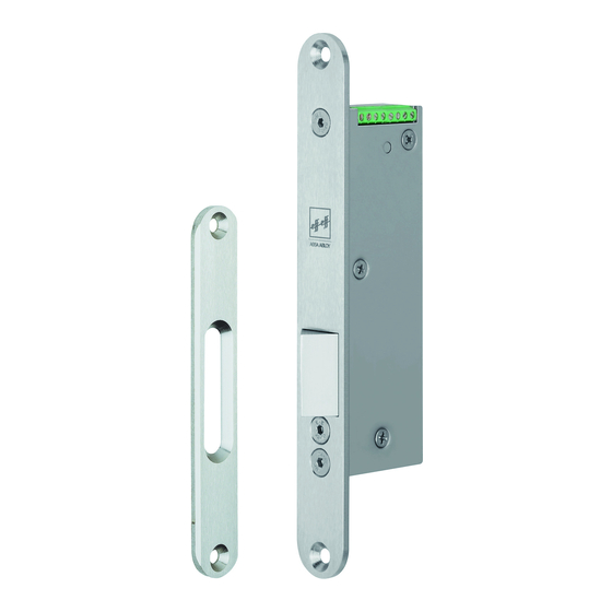
  • Page 44: Information Produit

    Information produit Gâche électronique 351M80 Généralités La gâche électronique 351M80 est équipé d’un moteur électrique qui permet de d'un système verrouiller des porte d’arrêter et des portes battantes. Il est conçu pour être d'entraînement monté à l’horizontale (sur le dormant) ou à la verticale sur le panneau de porte.
  • Page 45: Remarques

    Remarques À propos de ces instructions Ces instructions d’installation et de montage ont été rédigées à l’attention des électriciens et du personnel spécialement formé. Lisez ces instructions afin d’installer et d’utiliser l’appareil en toute sécurité et de pouvoir exploiter toutes les possibilités de mise en œuvre proposées.
  • Page 46: Consignes De Sécurité

    (jeu de battement entre la têtière et la contrepartie) soit de 3 mm (2 à 4,5 mm). Ne pas ouvrir la gâche électronique : la gâche électronique 351M80 ne doit pas être ouvert, car cela pourrait l’endommager. Ne pas le peindre : la gâche électronique 351M80 ne doit pas être revêtu d’une couche de peinture ou d’autres substances.
  • Page 47: Explication De La Terminologie Employée

    Explication de la terminologie employée Terme Description – Rupture de Selon le principe de verrouillage rupture de courant, la porte se verrouille en pré- courant sence de courant électrique. – Têtière Le terme têtière désigne la contrepartie de la serrure fixée sur le dormant. –...
  • Page 48: Fonctions Et Utilisation

    Contacts de signalisation La gâche électronique 351M80 détecte la porte. Un contact sec renseigne sur la contact de porte position de la porte (fermée ou ouverte). exempt de potentiel La gâche électronique 351M80 détecte la porte.
  • Page 49: Montage

    Danger de trébuchement en cas de pose dans le plancher : la gâche électronique 351M80 ne doit pas être posé dans le plancher. Il existe un danger de trébuche- ment et les pas et la saleté peuvent détruire la gâche électronique 351M80.
  • Page 50 Respecter les tolérances de la tension d’alimentation : la tension de service mesurée au gâche électronique 351M80 à courant nominal doit se trouver dans les limites de tolérances données. Le fait de dépasser ou de descendre sous les limites des tolérances entraîne des dommages ou des dysfonctionnements.
  • Page 51 Verticalement, la tolérance est de ±4,5 mm. Vissez la gâche électronique 351M80 dans la poche de serrure (Fig. 4). Vissage du gâche Vérifiez la souplesse de mouvement du gâche électronique 351M80.
  • Page 52: Montage Dans Le Cadre De Porte

    9 La gâche électronique 351M80 est entièrement monté et opérationnel. Montage dans le cadre de porte Si la gâche électronique 351M80 est monté dans le cadre de porte, la patte de montage SETLA M5 (« Patte de montage SETLA M5 », page 60) permet d’ajuster la position de la têtière de 2 mm (Fig.
  • Page 53 Fig. 5: A -A Montage avec patte de montage SETLA M5 et cales 1 - SETLA M5 2 - Cales 3 - Panneau de porte 4 - Têtière B - B 12,5 SELTA M5 (optional) Montage...
  • Page 54: Raccordement Électrique

    Raccordement électrique La gâche électronique 351M80 est équipé de contacts de signalisation exempts de potentiel. Un interrupteur Reed en guise de contact de porte (RR) est commuté via des aimants situés dans la têtière et indique l’état de fermeture de la porte.
  • Page 55 Fig. 6: Schéma de raccordement avec AKRR contact de porte RR et contact à ancrage AKRR − Montage...
  • Page 56: Caractéristiques Techniques

    Caractéristiques techniques Dimensions de cales et têtière contrepartie Fig. 7: Cales Têtière contrepartie Gâche électronique Plan technique (optionnel) 351M80 contenant les cotes de montage de gâche électronique, cales et têtière t=0,5 Ø10,4 x 90° Ø5,5 Ø6 A - A Ø17,2 Ø10...
  • Page 57: Dimensions Têtière De Serrure

    Dimensions têtière de serrure Fig. 8: Gâche électronique têtière de serrure Plan technique 351M80 contenant les cotes de montage de gâche électronique et têtière contre-partie Caractéristiques techniques...
  • Page 58: Caractéristiques Techniques

    Caractéristiques techniques Propriété Caractéristique Résistance aux effractions 5000 N Boîtier Acier inoxydable, soudé au laser, sans revêtement Verrou Acier Température de service -15 °C . . . +50 °C Course du verrou 10 mm Position de montage universelle Jeu de feuillure 3 mm (2 à...
  • Page 59 Caractéristiques techniques...
  • Page 60: Accessoires, Maintenance, Garantie, Mise Au Rebut

    Patte de montage SETLA M5 La patte de montage SETLA M5 décrite au chapitre « Montage », page 49, n’est pas livrée avec la gâche électronique 351M80 et peut être commandée séparément : effeff – patte de montage SETLA M5...
  • Page 61: Garantie

    Garantie Le délai de garantie légal s’applique. Si le produit est défectueux, adressez-vous à l’une de nos succursales dans votre pays. Vous trouverez les adresses au verso de ces instructions. L’ouverture du produit entraîne l’annulation de la garantie. Nous n’octroierons La garantie aucune garantie si vous utilisez un lubrifiant ou des accessoires autres que ceux s'applique...
  • Page 64 ASSA ABLOY is the global leader in door opening solutions, dedicated to satisfying end-user needs for security, safety and convenience. www.assaabloy.com ASSA ABLOY Sicherheitstechnik GmbH Bildstockstraße 20 72458 Albstadt DEUTSCHLAND albstadt @ assaabloy.de Tel. + 497431 123-0 Fax + 497431 123-240...

Table des Matières