Craftsman CMXEOCG232 Manuel Du Propriétaire
Table des Matières
Les langues disponibles
Les langues disponibles
Liens rapides
Owner's Manual
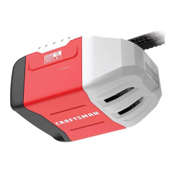
GARAGE DOOR OPENER
For Residential Use Only
MODELS CMXEOCG232 and CMXEOCG472
READ AND FOLLOW ALL SAFETY RULES AND OPERATING INSTRUCTIONS BEFORE FIRST USE OF THIS PRODUCT.
FASTEN THE MANUAL NEAR THE GARAGE DOOR AFTER INSTALLATION.
PERIODIC CHECKS OF THE OPENER ARE REQUIRED TO ENSURE SAFE OPERATION.
DO NOT INSTALL ON A ONE-PIECE DOOR IF USING DEVICES OR FEATURES PROVIDING UNATTENDED CLOSE.
UNATTENDED DEVICES AND FEATURES ARE TO BE USED ONLY WITH SECTIONAL DOORS. SEE PAGE 3.
WWW.CRAFTSMAN.COM
Chapitres
Table des Matières
Dépannage

Manuels Connexes pour Craftsman CMXEOCG232


Sommaire des Matières pour Craftsman CMXEOCG232
- Page 47 Ouvre-porte de garage Pour utilisation résidentielle uniquement. MODÈLES CMXEOCG232 ET CMXEOCG472 LIRE ET OBSERVER TOUTES LES RÈGLES DE SÉCURITÉ ET LE MODE D’EMPLOI AVANT D’UTILISER CE PRODUIT POUR LA PREMIÈRE FOIS. FIXER LE MANUEL À PROXIMITÉ DE LA PORTE DU GARAGE APRÈS L’INSTALLATION.
- Page 48 Tester la puissance du signal Wi-Fi® dans le garage Utilisation de votre ouvre-porte de garage Planification Utilisation de la commande de porte – Modèle CMXEOCG232 Contenu de la boîte Utilisation de la commande de porte – Modèle CMXEOCG472 Inventaire des fixations Télécommande...
-
Page 49: Introduction
INTRODUCTION PRÉPARATION DE LA PORTE DE GARAGE EXAMEN DES SYMBOLES DE SÉCURITÉ ET DES MOTS DE SIGNALEMENT Pour éviter des BLESSURES GRAVES, voire MORTELLES : Cet ouvre-porte de garage a été conçu et mis à l’essai dans le but d’offrir un service sûr à... -
Page 50: Outils Nécessaires
OUTILS NÉCESSAIRES TESTER LA PUISSANCE DU SIGNAL WI-FI ® DANS LE GARAGE Lors de l’assemblage, de l’installation et du réglage de l’actionneur de porte, les instructions feront appel aux outils à main illustrés ci-dessous. Surveillez et commandez votre porte de garage à partir de n’importe quel endroit avec ®... -
Page 51: Planification
PLANIFICATION INSTALLATION DE PORTE ARTICULÉE Identifier le type et la hauteur de votre porte de garage. Examiner la région du garage pour noter si l’une des conditions ci-après s’applique à votre installation. Des • Le panneau porte est-il en acier, aluminium, fibre de verre ou s’agit-il matériaux supplémentaires peuvent être nécessaires. - Page 52 PLANIFICATION (SUITE) INSTALLATIONS DE PORTE RIGIDE Sans un système d’inversion de sécurité bien installé, des personnes (plus • En règle générale, une porte rigide ne nécessite aucun renfort. Pour une particulièrement les petits enfants) pourraient être GRIÈVEMENT BLESSÉES ou porte légère, consulter l’information ayant trait aux portes articulées à TUÉES par une porte de garage qui se referme.
-
Page 53: Contenu De La Boîte
Le choix des accessoires dépendra du modèle Conserver la boîte et le matériel d’emballage jusqu’à ce que l’installation et les acheté. S’il manque quoi que ce soit, vérifier le matériel d’emballage. réglages soient terminés. CMXEOCG232 CMXEOCG472 Écarteur de chaîne Télécommande à trois boutons Sonnette de porte standard Tableau de commande à... -
Page 54: Inventaire Des Fixations
INVENTAIRE DES FIXATIONS Séparer toutes les fixations et les regrouper comme illustré ci-dessous aux fins des opérations de montage et d’installation. QUINCAILLERIE D’ASSEMBLAGE Boulon de 1/4 po-20 x 1 3/4 po Maillon de raccord (2) Écrou de 3/8 po Boulon de poulie Trolley Threaded Shaft Rondelle-frein de 3/8 po Contre-écrou de ¼ po-20 QUINCAILLERIE D’INSTALLATION... -
Page 55: Assemblage
ASSEMBLAGE ÉTAPE 1 ASSEMBLAGE ÉTAPE 2 ASSEMBLAGE DU RAIL ET INSTALLATION DU CHARIOT FIXATION DU RAIL AU MOTEUR Afin de prévenir une BLESSURE occasionnée par un pincement, garder les mains Afin d’éviter d’endommager GRAVEMENT l’ouvre-porte de garage, utiliser et les doigts à l’écart des articulations lors de l’assemblage du rail. UNIQUEMENT les boulons et les fixations montés sur le dessus de l’ouvre-porte. -
Page 56: Installer La Poulie
ASSEMBLAGE ÉTAPE 3 INSTALLER LA POULIE 1. Poser la chaîne/le câble à côté du rail, comme illustré. Saisir l’extrémité avec la boucle du câble et passer environ 30 cm (12 po) de câble par la fenêtre. Laisser prendre jusqu’à l’étape 4 du montage. 2. Retirer le ruban de la poulie. Le centre intérieur devrait être prégraissé. S’il est sec, graisser à... -
Page 57: Installer La Chaîne/Le Câble
ASSEMBLAGE ÉTAPE 4 REMARQUE : L’apparence de votre produit peut différer des produits illustrés ici. INSTALLER LA CHAÎNE/LE CÂBLE Pour éviter d’éventuelles BLESSURES GRAVES aux doigts par suite du mouvement de l’ouvre-porte : • Garder TOUJOURS la main à l’écart du pignon lorsque l’ouvre-porte fonctionne. -
Page 58: Installation
ASSEMBLAGE ÉTAPE 5 Figure 1 Écrou Ron- Arbre fileté du TENSION DE LA CHAÎNE extérieur delle-frein chariot Vers serrer l’écrou extérieur 1. Dévisser l’écrou intérieur et la rondelle-frein de l’arbre fileté du chariot, à l’écart du chariot. 2. Pour tendre la chaîne, tourner l’écrou extérieur dans le sens illustré (Figure Écrou intérieur Vers serrer l’écrou 3. -
Page 59: Déterminer L'emplacement Du Support De Linteau
INSTALLATION ÉTAPE 1 MONTAGE AU Plafond non fini PLAFOND DÉTERMINER L’EMPLACEMENT DU SUPPORT DE LINTEAU FACULTATIF POUR SUPPORT DE LINTEAU Mur du linteau Pour éviter des BLESSURES GRAVES, voire MORTELLES : Ligne centrale verticale de la porte de garage • Le support de linteau DOIT être fixé DE MANIÈRE RIGIDE à la solive sur le linteau ou le plafond, sinon la porte de garage pourrait ne PAS remonter, au Supports structuraux... -
Page 60: Installer Le Support De Linteau
INSTALLATION ÉTAPE 2 INSTALLATION DU SUPPORT DE LINTEAU AU PLAFOND INSTALLATION DU SUPPORT DE LINTEAU 1. Prolonger l’axe vertical sur le plafond, comme illustré. Le support de linteau peut être fixé au mur, au-dessus de la porte, ou au plafond. 2. Centrer le support sur l’axe vertical à 15 cm (6 po) au maximum du mur. Suivre les instructions qui répondent le mieux aux besoins particuliers. -
Page 61: Fixation Du Rail Sur Le Support De Linteau
INSTALLATION ÉTAPE 3 FIXATION DU RAIL SUR LE SUPPORT DE LINTEAU 1. Positionner l’ouvre-porte de garage sur le plancher, juste sous le support de linteau. Utiliser le matériel d’emballage pour le protéger. REMARQUE : Si le ressort de la porte gêne, il faudra demander de l’aide. Demander à... -
Page 62: Positionner L'ouvre-Pore
INSTALLATION ÉTAPE 4 POSITIONNER L’OUVRE-PORE Suivre les instructions qui se rapportent à votre porte de garage particulière, en Pour éviter des dommages à l’ouvre-porte de garage, faire reposer le rail de consultant les illustrations. l’ouvre-porte de garage sur un 2 x 4 placé sur la section supérieure de la porte. PORTE ARTICULÉE OU RIGIDE AVEC GUIDE Un 2 x 4 posé... -
Page 63: Accrocher L'ouvre-Porte
INSTALLATION ÉTAPE 5 ACCROCHER L’OUVRE-PORTE Figure 1 Supports structuraux Pour éviter d’éventuelles BLESSURES GRAVES par suite de la chute d’un ouvre- porte de garage, fixer l’ouvre-porte SOLIDEMENT aux solives du garage. Des ancrages en béton DOIVENT être utilisés lors de l’installation des supports Tire-fond de 5/16 dans la maçonnerie. -
Page 64: Installation Des Ampoules
Les ampoules à DEL peuvent causer un brouillage radioélectrique avec la • Ne JAMAIS utiliser la poignée pour ouvrir ou fermer la porte. Il y a risque de télécommande. Aller à craftsman.com pour une liste des ampoules à DEL chute si le nœud de la corde se défait. -
Page 65: Fixation Du Support De Porte
INSTALLATION ÉTAPE 8 FIXATION DU SUPPORT DE PORTE Support de linteau Les portes de garage en fibre de verre, en aluminium ou en acier léger DOIVENT être renforcées AVANT d’installer le support de porte. Contacter le fabricant de la porte de garage ou l’installateur pour les instructions relatives aux renforts ou obtenir une trousse de renforts. - Page 66 FIXATION DU SUPPORT DE PORTE (SUITE) PORTES RIGIDES Prière de lire et de suivre les avertissements et les instructions de renforcement à la page précédente. Ils s’appliquent également aux portes rigides. • Centrer le support de porte sur le dessus de la porte, en l’alignant sur le support de linteau, comme illustré.
-
Page 67: Fixation De La Biellette De La Porte Au Chariot
INSTALLATION ÉTAPE 9 Poulie au moins 20 cm Figure 1 FIXATION DE LA BIELLETTE DE LA PORTE AU CHARIOT (8 po) Suivre les instructions qui s’appliquent au type de votre porte, comme illustré ci- dessous et à la page suivante. Chariot Chariot IMPORTANT : La rainure de la biellette droite DOIT pointer loin de la biellette courbée intérieur extérieur (Figure 4). -
Page 68: Fixation Des Étiquettes D'avertissement
RACCORDEMENT DE BIELLETTE DE LA PORTE AU CHARIOT (SUITE) Figure 6 Porte rigide sans guide TOUTES LES PORTES RIGIDES Poulie Chariot intérieur Patte du rail IMPORTANT : La rainure de la biellette droite DOIT pointer loin de la biellette courbée Chariot extérieur (Figure 5) . -
Page 69: Installation De La Commande De Porte - Modèle Cmxeocg232
INSTALLATION ÉTAPE 11 INSTALLATION DE LA COMMANDE DE PORTE – MODÈLE CMXEOCG232 Installer la commande de porte bien en vue de la porte de garage, hors de portée des jeunes enfants à une hauteur d’au moins 1,5 m (5 pi) du sol, des paliers, des Pour prévenir d’éventuelles BLESSURES GRAVES, voire MORTELLES suite à... -
Page 70: Installer La Commande De Porte - Modèle Cmxeocg472
INSTALLATION ÉTAPE 11 INSTALLER LA COMMANDE DE PORTE - MODÈLE CMXEOCG472 Pour prévenir d’éventuelles BLESSURES GRAVES, voire MORTELLES suite à une INTRODUCTION électrocution : REMARQUE : Les anciennes commandes de porte et les produits de tiers ne sont pas • S’assurer que l’alimentation est coupée AVANT d’installer la commande de la compatibles. - Page 71 INSTALLATION ÉTAPE 12 ESSAI DU SYSTÈME D’INVERSION DE SÉCURITÉ RENSEIGNEMENTS IMPORTANTS AU SUJET DU CAPTEUR D’INVERSION DE SÉCURITÉ Le capteur d’inversion de sécurité doit être connecté et aligné correctement avant que l’ouvre-porte de garage n’entame le mouvement de fermeture Le capteur de transmission (doté d’un témoin à DEL ambre) transmet un faisceau de S’assurer que l’ouvre-porte de garage est hors tension AVANT d’installer le lumière invisible au capteur de réception (muni d’un témoin à...
-
Page 72: Installer Le Système D'inversion De Sécurité
INSTALLER LE SYSTÈME D’INVERSION DE SÉCURITÉ (SUITE) Figure 1 MONTAGE DU GUIDE DE PORTE (CÔTÉ DROIT) INSTALLATION DES SUPPORTS S’assurer que l’ouvre-porte est hors tension. Installer et aligner les supports de Guide de porte manière à ce que les capteurs d’inversion de sécurité se fassent face de part et Rebord d’autre de la porte du garage, le faisceau n’étant pas à... - Page 73 INSTALLER LE SYSTÈME D’INVERSION DE SÉCURITÉ (SUITE) Figure 5 MONTAGE ET CÂBLAGE DES CAPTEURS D’INVERSION DE SÉCURITÉ Écrou à oreilles Boulons de Montage : carrosserie 1. Glisser un boulon de carrosserie de 1/4 po-20 x 1/2 po dans la fente de chaque capteur. Utiliser des écrous à oreilles pour fixer les capteurs d’inversion de sécurité...
-
Page 74: Exigences Électriques
INSTALLATION ÉTAPE 13 INSTALLATION ÉTAPE 14 EXIGENCES ÉLECTRIQUES ALIGNEMENT DES CAPTEURS D’INVERSION DE SÉCURITÉ La porte ne se fermera pas si les capteurs n’ont pas été installés et alignés correctement. Si le faisceau lumineux est obstrué ou mal aligné quand la porte se ferme, celle-ci Pour éviter toute BLESSURE potentielle GRAVE, voire MORTELLE, par inversera sa course et l’éclairage de l’ouvre-porte de garage clignotera dix fois. -
Page 75: Réglage
RÉGLAGE INTRODUCTION Sans un système d’inversion de sécurité bien installé, des personnes (plus particulièrement les petits enfants) pourraient être GRIÈVEMENT BLESSÉES ou Votre ouvre-porte de garage a été conçu avec des commandes électroniques pour TUÉES par une porte de garage qui se referme. simplifier la configuration et les réglages. -
Page 76: Programmation De La Course
RÉGLAGE ÉTAPE 1 PROGRAMMATION DE LA COURSE Sans un système d’inversion de sécurité bien installé, des personnes (plus particulièrement les petits enfants) pourraient être GRIÈVEMENT BLESSÉES ou 1. Enfoncer et tenir le bouton de TUÉES par une porte de garage qui se referme. réglage jusqu’à... -
Page 77: Essai Du Système D'inversion De Sécurité
RÉGLAGE ÉTAPE 2 ESSAI DU SYSTÈME D’INVERSION DE SÉCURITÉ MISE À L’ESSAI 1. La porte étant entièrement ouverte, placer une planche de 3,8 cm (1 1/2 de po) d’épaisseur (ou un 2 x 4 à plat) sur le sol, centrée sous la porte de Sans un système d’inversion de sécurité... -
Page 78: Commande Myq® Par Téléphone Intelligent
COMMANDE myQ ® Bouton TÉLÉPHONE INTELLIGENT « LEARN » (apprentissage) MODÈLE CMXEOCG472 UNIQUEMENT SE CONNECTER AVEC UN TÉLÉPHONE INTELLIGENT Une DEL sur l’ouvre-porte de garage indiquera l’état du Wi-Fi. Voir le IL VOUS FAUDRA : tableau ci-dessous. • Un téléphone intelligent, tablette ou ordinateur portatif activés par Wi-Fi •... -
Page 79: Fonctionnement
FONCTIONNEMENT IMPORTANTES CONSIGNES DE SÉCURITÉ Pour réduire le risque de BLESSURES GRAVES, voire MORTELLES : 1. LIRE ET OBSERVER TOUS LES AVERTISSEMENTS ET TOUTES LES INSTRUCTIONS. 9. Après avoir effectué QUELQUE réglage que ce soit, on DOIT faire l’essai 2. Garder TOUJOURS la télécommande hors portée des enfants. Ne JAMAIS laisser du système d’inversion de sécurité. -
Page 80: Caractéristiques
UTILISATION DE LA COMMANDE DE PORTE – MODÈLE remontera jusqu’à la position entièrement ouverte et les lumières de l’ouvre-porte CMXEOCG232 clignoteront 10 fois. Si la porte est complètement ouverte et que les capteurs d’inversion de sécurité ne sont pas installés ou s’ils sont mal alignés, la porte ne se SYNCHRONISATION DE LA COMMANDE DE PORTE : Pour synchroniser la commande de... -
Page 81: Utilisation De La Commande De Porte - Modèle Cmxeocg472
UTILISATION DE LA COMMANDE DE PORTE – MODÈLE CMXEOCG472 APPRENTISSAGE D’UN DISPOSITIF SYNCHRONISATION DE LA COMMANDE DE PORTE ® Les télécommandes, claviers sans fil ou accessoires myQ compatibles peuvent être programmés à l’ouvre-porte de garage en appuyant sur le bouton d’apprentissage Pour synchroniser la commande de porte à... -
Page 82: Télécommande
POUR EFFACER LA MÉMOIRE TÉLÉCOMMANDE EFFACER TOUTES LES TÉLÉCOMMANDES ET TOUS LES CLAVIERS Votre télécommande a été programmée en usine pour faire fonctionner votre ouvre- SANS FIL porte de garage. 1. Enfoncer et tenir le bouton d’apprentissage de l’ouvre-porte de garage Les télécommandes plus anciennes ne sont PAS compatibles. -
Page 83: Ouverture Manuelle De La Porte
OUVERTURE MANUELLE DE LA PORTE LA PILE DE LA TÉLÉCOMMANDE Pour prévenir d’éventuelles BLESSURES GRAVES ou MORTELLES par suite de la Pour éviter des BLESSURES GRAVES, voire MORTELLES : chute d’une porte de garage : • Ne JAMAIS laisser des enfants s’approcher de la batterie. •... -
Page 84: Dépannage
DÉPANNAGE TABLEAU DIAGNOSTIQUE Des fonctions d’autodiagnostic ont été programmées dans votre ouvre-porte de garage. Les flèches vers le haut et le bas sur l’ouvre-porte de garage font clignoter les codes d’anomalie. LA FLÈCHE VERS LA FLÈCHE VERS SYMPTÔME SOLUTION LE HAUT LE BAS CLIGNOTE CLIGNOTE L’ouvre-porte de garage ne ferme pas... -
Page 85: Pièces De Réparation
041A7276 Coussinets d’usure PIÈCES POUR L’INSTALLATION LÉGENDE Nº DE PIÈCE DESCRIPTION 041A7367-7 Commande de sonnette de porte standard (Modèle CMXEOCG232) 041A9501 Tableau de commande à double fonction (Modèle CMXEOCG472) K010A0020 Pile au lithium de 3 V CR2032 K029B0137 Agrafe de pare-soleil 041A2828 Assemblage de la poignée et de la corde de... - Page 86 PIÈCES DE RÉPARATION - MODÈLE CMXEOCG232 PIÈCES D’ASSEMBLAGE DE L’UNITÉ DU MOTEUR LÉGENDE Nº DE PIÈCE DESCRIPTION LÉGENDE Nº DE PIÈCE DESCRIPTION 041A5615 Écarteur de chaîne 041D7742-7 Module de course 041C4220A Pignon et engrenage 041-0108 Couvercle 041-0125 Panneau d’extrémité avant avec toutes les...
- Page 87 PIÈCES DE RÉPARATION - MODÈLE CMXEOCG472 PIÈCES D’ASSEMBLAGE DE L’UNITÉ DU MOTEUR LÉGENDE Nº DE PIÈCE DESCRIPTION LÉGENDE Nº DE PIÈCE DESCRIPTION 041A5615 Écarteur de chaîne 041D7742-7 Module de course (« point de contrôle ») 041C4220A Pignon et engrenage 041-0177 Couvercle 041-0125 Panneau d’extrémité...
-
Page 88: Accessoires
Rallonge de rail de 2,44 m (8 pi) : CMXZDCG453 Télécommande : Pour permettre à une porte de 2,4 m (8 pi) de s’ouvrir Fonctionne avec TOUS les ouvre-portes CRAFTSMAN fabriqués complètement. depuis 1993. Comprend l’agrafe de pare-soleil. CMXZDCG4710 Rallonge de rail de 3 m (10 pi) : CMXZDCG440 Clavier sans fil :... -
Page 89: Guide De Sécurité Et D'entretien De L'ouvre-Porte De Garage Automatique
GUIDE DE SÉCURITÉ ET D’ENTRETIEN DE L’OUVRE-PORTE DE GARAGE AUTOMATIQUE SÉCURITÉ DES OUVRE-PORTES DE GARAGE - UNE DÉCISION AUTOMATIQUE Une porte de garage est le plus grand objet mobile de la maison. Dans le cas où la porte de garage et l’actionneur seraient mal réglés, une très grande force pourrait être exercée par la porte en se fermant, ce qui pourrait causer le piégeage d’enfants ou d’adultes et entraîner des blessures ou la mort. - Page 90 L’ENTRETIEN COURANT PEUT ÉVITER DES TRAGÉDIES Faire en sorte que l’inspection et la mise à l’essai mensuelles du système de porte de garage et de l’ouvre-porte fassent partie de vos tâches routinières. Étudiez votre manuel du propriétaire pour bien comprendre le fonctionnement de la porte et de l’ouvre-porte. Si vous ne possédez plus les manuels du propriétaire, contactez leur fabricant respectif et demandez de recevoir un exemplaire pour votre ou vos modèles particuliers.
- Page 92 Pour obtenir des réponses aux questions, dépanner des problèmes ou commander des pièces. Pour nous aider à mieux vous aider, enregistrez votre produit à www.craftsman.com/registration CRAFTSMAN® une marque déposée de Stanley Black & Decker, Inc., utilisée en vertu d’une licence. © 2020 CRAFTSMAN 114-5500FR...