Table des Matières

Publicité

Les langues disponibles
  • FR

Les langues disponibles

  • FRANÇAIS, page 29

Liens rapides

REACTOR USING MEDIUM PRESSURE LIGHT
INSTALLATION AND MAINTENANCE
MP 030 EL NM GB
Marque, Modèles et Brevets déposés - Produits exclusifs
MP030 EL
MANUAL CLEANING
(Picture MP 030)
MANUAL
Copyright BIO-UV - 29/01/2009
Page 1

Publicité

Table des Matières
loading

Sommaire des Matières pour BIO UV MP030 Serie

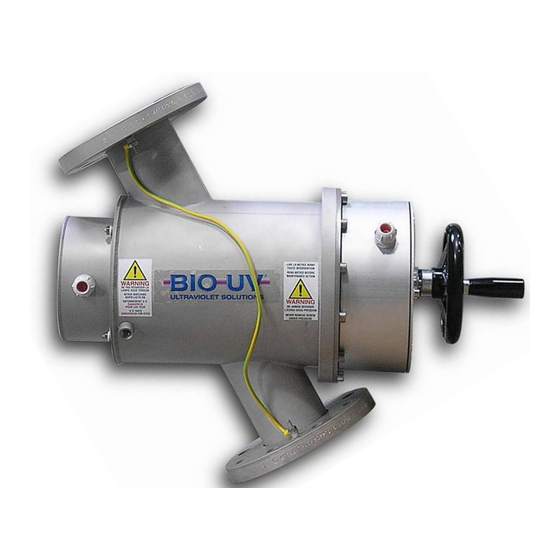
  • Page 1 REACTOR USING MEDIUM PRESSURE LIGHT MP030 EL MANUAL CLEANING (Picture MP 030) INSTALLATION AND MAINTENANCE MANUAL MP 030 EL NM GB Copyright BIO-UV - 29/01/2009 Marque, Modèles et Brevets déposés - Produits exclusifs Page 1...
  • Page 2: Compliance Certificate

    UVPS subsidiary of the BIO-UV COMPLIANCE CERTIFICATE CERTIFICATE OF CONFORMITY BIO-UV and this subsidiary, hereby declares that the following products BIO-UV MP Range comply to the following standards: NF EN 60439-1 (2000) CEM: EN55015 (Ed.00) + A1 (Ed.01) Number and year of EC stamp: CG-03-006 dated 29/01/2003 LS-03-51003/NL dated 20/02/03 Benoît GILLMANN...
  • Page 3: Table Des Matières

    We thank you for choosing a BIO-UV reactor. Our equipment has been designed to give you reliable and safe operation for many years to come. The BIO-UV reactors have been designed for speed and ease of installation. Their design also makes them easy to maintain.. Read these instructions carefully in order to optimise the operation of your reactor.
  • Page 4: Technical Characteristics

    A. TECHNICAL CHARACTERISTICS MP030 EL RANGE 600 W 1 KW 3 KW REACTOR Material Stainless steel 316L Finish Pickling and passivated Maximum service pressure 3 bars Weight (kg) Ø and body length (mm) 204 x 276 Overall length (mm) Volume (litres) 14,2 Connection type Flange...
  • Page 5: Electrical Section

    TESTS OF ACCEPTANCE Client: Order number: Unit designation: Serial number: Date: ELECTRICAL SECTION: Test date: Wiring carried out by: Protection classification: IP 54 Observation:………………………………………………………………………………………………… ……………………………………………………………………………………………………………… ……………………………………………………………………………………………………………… ……………………………………………………………………………………………………………… ………… MECHANICAL SECTION : DESIGNATION REFERENCE Quartz UVC Lamp Quartz joint Wiper joint Motor / electric jack Dimensions between flanges Bride...
  • Page 6: Maintenance File

    B. MAINTENANCE FILE CAUTION: This sheet must be kept up to date. It provides a record of the reactor’s operating cycle. Date Action MP 030 EL NM GB Copyright BIO-UV - 29/01/2009 Marque, Modèles et Brevets déposés - Produits exclusifs Page 6...
  • Page 7: Warnings And Safety

    C. WARNINGS AND SAFETY BIO-UV reactors are ready to install, no works is required inside the reactor. Read all the instructions in this manual before switching on the BIO-UV appliance. INSTALLATION RECOMMANDATIONS The reactor must be installed: in a technical room, protected from light and rain, after the filter(s), in a dry zone, ambient humidity must be <...
  • Page 8 USE AND MAINTENANCE ● Allow the ultraviolet lamp to cool for at least 30 minutes before handling. ● Never look at the ultraviolet lamps when lit. This may cause severe injuries or burns and may even lead to loss of eyesight. ●...
  • Page 9: Installation Of The Reactor

    D. INSTALLATION OF THE REACTOR LAMPS must be HORIZONTAL Overall installation view Reactor in a horizontal position Reactor in a vertical position Temperature Sensor supply General power General power supply supply Temperature Sensor supply UV lamps power supplies UV lamps power UV lamps power supply supply...
  • Page 10 Strictly follow the instructions: Clearance zone (mm) required Positioning of reactor to work on the reactor - The water channel is horizontal. - The UV lamps are horizontal. - The purges are at the base of the reactor. Lamps are in vertical position: PROHIBITED MP 030 EL NM GB Copyright BIO-UV - 29/01/2009...
  • Page 11 THE REACTOR MUST BE PROPERLY CONNECTED TO EARTH AS PER THE DIAGRAM BELOW Main switchboard UV cabinet 6 mm² minimum 6 mm² minimum 6 mm² minimum The earth wires marked are supplied with the UV reactor. The earth wire marked must be connected when the reactor is installed on site (6 mm²...
  • Page 12 COMPULSORY INSTALLATION INSTRUCTIONS It is preferable to install the UV reactor in By-Pass, and this must absolutely not be linked to pump operation. Instruction No. 1: The UV lamp must be HORIZONTAL whatever the position of the reactor. Instruction No.2: The reactor must be correctly linked to the earth with a suitable wire of 6 mm² minimum.
  • Page 13: Flow Sensor

    E. FLOW SENSOR The flow sensor starts the unit when the flow is present and stops it when the flow rate is insufficient in order to ensure sufficient time for lamp cooling. The flow sensor is located on the reactor as on this picture: At the start-up of reactor, it is NECESSARY to carry out a calibration on the basis of the MINIMUM FLOW RATE in your installation..
  • Page 14: Manual Of The Monitor Bio-Uv Miii

    F. MANUAL OF THE MONITOR BIO-UV MIII Radiance UV Reset counter at Set cleaning Set power management zero time cycle regulation During 5s During 5s During 5s During 5s Set main alarm Set pre-alarm threshold threshold Activate/Deactivate EGEND automatic cleaning Main Display Flow Cleaning...
  • Page 15: General Information

    GENERAL INFORMATION: This operating manual describes all possible options, Some of them aren’t available on your device according to your reactor type. Definition of the 3 letters on the first display means that the reactor is switched on and operating. means that the water is flowing and that the flow is adequate in relation to the setting that you made on the flowmeter.
  • Page 16 CONTENT OF MENUS AND SUB-MENUS: Use the + or – keys to change from one menu to another. Press on key A for 5 seconds to enter a menu. When the word "OFF" is displayed, this means that the display option is not available on your device. Display of UVC intensity measured by the sensor.
  • Page 17: Alarm Contact (Option)

    G. ALARM CONTACT (OPTION) The pre-alarm and main-alarm faults are indicated by snap contacts on the monitor which are transmitted to terminal strips (see the wiring diagram in order to identify them). The snap contacts are normally closed. They open when respective alarms are active. H.
  • Page 18: Inspections And Preventive Maintenance

    I. INSPECTIONS AND PREVENTIVE MAINTENANCE In the event of work on the UV reactor, ensure that personnel are qualified and authorised. RECOMMENDATIONS FOR VERIFYING OPERATION AND USE The following points must be regularly checked in order to make sure that the UV reactor is operating perfectly: •...
  • Page 19: Changeover

    RECOMMENDED INSPECTIONS AND PREVENTIVE MAINTENANCE Changing UV lamps At the end of their life span: - either display on the Millénium III monitor: UV intensity <50% - or combined chlorine rate in the basin OPERATIONS ON EACH UV LAMP AT LEAST ONCE CHANGEOVER PER YEAR Checking the general state of the UV...
  • Page 20 CHANGING UV LAMP AND QUARTZ SLEEVE SWITCH OFF the reactor, CUT the POWER source and EMPTY IT Unscrew and remove the 2 covers. Remove the wires from the lamp on both sides by unscrewing the terminals (only the cables white supplying the lamp). Unscrew the aluminium lamp base, 3 screws, on both sides.
  • Page 21 Centre the quartz sleeve, it should stick out equally on both sides. Change the quartz seals: (Put new seals at each change of lamp) ● lubricate the seals using food grade grease, ● position them around the sleeve, ● push them fully home in their housing using your nail (help you with aluminium washer.
  • Page 22: Changing The Wiper Seals

    J. CHANGING THE WIPER SEALS The wiper seal has two faces, which are easy to identify: one has a flat white surface, the other has a metal reinforcement. Carry out all the quartz sleeve disassembly operations. Remove the toothed coupling. Unscrew the cleaning shaft nut.
  • Page 23: Electrical Unit

    K. ELECTRICAL UNIT N° Désignation MP030 EL 600 MP030 EL 1KW MP030 EL Disconnecting switch ELE000117 ELE000117 ELE000117 Main pole ELE001080 ON/OFF switch ELE000271 ELE000271 ELE000271 * Only with Automatic cleaning option ELE000297 ELE000297 ELE000297 Hide ligth white LED white ELE000274 ELE000274 ELE000274...
  • Page 24: Blown Up View

    L. BLOWN UP VIEW UV Sensor Drain plug N° Designation Reference STD003903 Operating handwheel ASM003970 Toothed coupling USI000018 Nut of cleaning Flat washer PIE003982 Seals (x2) JTS002715 Drain plug ACC000410 Lamp base PIE000500 PIE001067 Spacing washer* LPE001072 Lamp 600W LPE000010 Lamp 1000W Lamp 2500W LPE004371...
  • Page 25 WARRANTIES Units in the BIO-UV range are guaranteed subject to the following conditions: 5 years for the stainless steel reactor (materials and welding) except in the event of use in a highly corrosive environment (brackish or very salty, e.g.: seawater). 2 years for all other components excepting the UV lamp (consumable).
  • Page 26 ANNEX 1 Clearance dimensions Blown up view Designation MP 030 EL NM GB Copyright BIO-UV - 29/01/2009 Marque, Modèles et Brevets déposés - Produits exclusifs Page 26...
  • Page 27: Electrical Diagrams

    ANNEX 2 Electrical diagrams MP 030 EL NM GB Copyright BIO-UV - 29/01/2009 Marque, Modèles et Brevets déposés - Produits exclusifs Page 27...
  • Page 28: Nettoyage Manuel

    RÉACTEUR UV MOYENNE PRESSION MP030 EL NETTOYAGE MANUEL (Photo MP 030) NOTICE DE MONTAGE ET D’ENTRETIEN MP 030 NM FR COPYRIGHT BIO-UV - 04/02/2009 MARQUE, MODELES ET BREVETS DEPOSES - PRODUITS EXCLUSIFS PAGE 1...
  • Page 29: Certificat De Conformite

    UVPS filiale de BIO-UV CERTIFICAT DE CONFORMITE CERTIFICATE OF CONFORMITY Nous, société BIO-UV et ses filiales, déclarons que les produits De la gamme MP Sont conformes aux normes suivantes : NF EN 60439-1 (2000) CEM : EN55015 (Ed.00) + A1 (Ed.01) Numéro et apposition du marquage CE : CG-03-006 du 29/01/2003 LS-03-51003/NL du 20/02/03...
  • Page 30 Nous vous remercions d’avoir choisi un réacteur BIO-UV. Notre matériel a été conçu pour vous offrir un fonctionnement fiable et sécurisé pendant de longues années. Les réacteurs BIO-UV ont été conçus pour être rapidement et facilement installés. Leur conception permet également une maintenance aisée. Lisez attentivement cette notice afin de bénéficier du fonctionnement optimum de votre réacteur.
  • Page 31: Caracteristiques Techniques

    A. CARACTERISTIQUES TECHNIQUES GAMME MP 030 600 W 1000 W 2500 W RÉacteur MATIERE INOX 316 L FINITION MICROBILLE PRESSION DE SERVICE MAX 3 BARS POIDS Ø ET LONGUEUR DU CORPS 204 X 276 (MM) LONGUEUR HORS TOUT (MM) VOLUME (LITRES) 14,2 TYPE DE RACCORDEMENT BRIDES...
  • Page 32 (2) Sauf demande spécifique à la commande. MP 030 NM FR COPYRIGHT BIO-UV - 04/02/2009 MARQUE, MODELES ET BREVETS DEPOSES - PRODUITS EXCLUSIFS PAGE 5...
  • Page 33: Test D'acceptation

    TEST D’ACCEPTATION Client : Numéro de commande : Désignation de l’appareil : Numéro de série : Date : PARTIE ÉLECTRIQUE : Date du test : Câblage effectué par : Indice de protection : IP 54 Observation :………………………………………………………………………………………………… ……………………………………………………………………………………………………………… ……………………………………………………………………………………………………………… ……………………………………………………………………………………………………………… …………...
  • Page 34: Fiche De Maintenance

    B. FICHE DE MAINTENANCE ATTENTION : Cette fiche doit être impérativement tenue à jour. Elle témoignera de la vie du réacteur. Date Opération effectuée Exécutée par MP 030 NM FR COPYRIGHT BIO-UV - 04/02/2009 MARQUE, MODELES ET BREVETS DEPOSES - PRODUITS EXCLUSIFS PAGE 7...
  • Page 35: Avertissements Et Securite

    C. AVERTISSEMENTS ET SECURITE Les réacteurs BIO-UV sont livrés prêts à raccorder, aucune opération n’est nécessaire à l’intérieur de l’appareil. Lire toutes les instructions de ce manuel avant de faire fonctionner le réacteur. INSTALLATION RECOMMANDATIONS Le réacteur doit être installé : dans un local technique, à...
  • Page 36 UTILISATION et MAINTENANCE ● Eteindre l’appareil 30 minutes avant toute intervention de façon à le laisser refroidir. ● Ne jamais regarder la lampe Ultra-violet allumée sans lunette de protection. Cela peut provoquer de sévères blessures ou brûlures, voire causer la perte de la vue. ●...
  • Page 37: Installation Du Reacteur

    Les LAMPES sont impérativement en position HORIZONTALE D. INSTALLATION DU REACTEUR Vue d’ensemble de l’installation REACTEUR EN POSITION HORIZONTALE REACTEUR EN POSITION VERTICALE Alimentation Sonde de température Alimentation Alimentation Générale Générale Alimentation Sonde de température Alimentations Lampe UVC Alimentation Alimentation Lampe UVC Lampe UVC MP 030 NM FR...
  • Page 38: Positionnement Du Reacteur

    Respecter impérativement les consignes suivantes : ZONE DE DEGAGEMENT (MM) NECESSAIRE POSITIONNEMENT DU REACTEUR POUR TOUTE INTERVENTION SUR LE REACTEUR - LA CANALISATION D’EAU EST HORIZONTALE. - LES LAMPES SONT POSITIONNEES HORIZONTALEMENT. - LA PURGE EST EN BAS DU REACTEUR. LES LAMPES SONT EN POSITION VERTICALE : MP 030 NM FR COPYRIGHT BIO-UV - 04/02/2009...
  • Page 39 INTERDIT MP 030 NM FR COPYRIGHT BIO-UV - 04/02/2009 MARQUE, MODELES ET BREVETS DEPOSES - PRODUITS EXCLUSIFS PAGE 12...
  • Page 40: Le Reacteur Doit Etre Correctement Relie A La Terre Suivant Le Schema Ci-Dessous

    LE REACTEUR DOIT ETRE CORRECTEMENT RELIE A LA TERRE SUIVANT LE SCHEMA CI-DESSOUS Armoire électrique principale Armoire UV 6 mm² minimum 6 mm² minimum 6 mm² minimum Les fils de terre repère sont fournis avec le réacteur UV. Le fil de terre repère doit être raccorder lors de l’installation du réacteur sur le site (6 mm²...
  • Page 41: Consignes Imperatives Pour L'installation

    CONSIGNES IMPERATIVES POUR L’INSTALLATION Il est préférable d’installer le réacteur UV en By-Pass, et ce dernier ne doit absolument pas être asservi au fonctionnement des pompes. Consigne N°1 : La lampe UV doit impérativement être HORIZONTALE quelque soit la position du réacteur.
  • Page 42: Controleur De Debit

    CONTROLEUR DE DEBIT Le contrôleur de débit a pour fonction de démarrer le réacteur UV lorsque le débit est présent et de le stopper lorsque le débit de l’installation est insuffisant pour assurer un refroidissement correct des lampes. Le contrôleur de débit est positionné sur le réacteur et se présente comme sur la photo. A la mise en service du réacteur, il faut IMPERATIVEMENT effectuer l’étalonnage du contrôleur de débit sur le DEBIT MINIMUM de votre installation.
  • Page 43: Manuel De Fonctionnement Du Moniteur Bio-Uv Miii

    E. MANUEL DE FONCTIONNEMENT DU MONITEUR BIO-UV MIII Gestion du Mise à zéro des Réglage du cycle horaire Réglage de la régulation rayonnement UV compteurs de nettoyage de puissance Pendant 5s Pendant 5s Pendant 5s Pendant 5s Réglage du seuil Réglage du seuil Eteindre et de pré-alarme...
  • Page 44: Generalites

    GENERALITES : La présente notice traite toutes les options possibles, certaines ne seront donc pas disponible en fonction de votre type d’appareil. Définition des 3 premières lettres de l’affichage M signifie que le réacteur est sous tension et en marche. signifie que le débit est présent et suffisamment important par rapport au seuil que vous avez préalablement réglé...
  • Page 45: Composition Des Menus Et Sous-Menus

    COMPOSITION DES MENUS ET SOUS-MENUS : Le passage entre chaque menu se fait par les touches + ou - . L’entrée dans un menu se fait par pression sur la touche A pendant 5 secondes. Lorsque le mot « INACTIF » est affiché, cela signifie que l’option se référant à l’affichage n’est pas présente sur votre appareil.
  • Page 46: Contact Des Alarmes (Option)

    F. CONTACT DES ALARMES (option) Les défauts de pré-alarme et de main-alarme sont signalés par des contacts secs sur le moniteur qui sont reportés sur des borniers (se reporter au schéma électrique pour les identifier). Les contacts sont normalement fermés. Ils s’ouvrent lorsque les alarmes respectives sont actives. G.
  • Page 47: Exploitation Et Maintenance Du Reacteur Uv

    H. EXPLOITATION ET MAINTENANCE DU REACTEUR UV En cas d’intervention sur le réacteur UV, s’assurer que le personnel soit qualifié et habilité. PRECONISATION DE CONTROLE DE FONCTIONNEMENT ET D’EXPLOITATION Les points suivants doivent être régulièrement contrôlés afin de s’assurer du parfait fonctionnement du réacteur UV : •...
  • Page 48 PRECONISATIONS DE CONTROLES ET MAINTENANCE PREVENTIVE CHANGEMENT DES EN FIN DE VIE : LAMPES UV - SOIT AFFICHAGE DU MONITEUR MILLENIUM III : INTENSITE UV <50% - SOIT TAUX DE CHLORE COMBINE DANS LE BASSIN OPERATIONS A CHAQUE AU MINIMUM 1 CHANGEMENT FOIS PAR AN DE LAMPE UV...
  • Page 49 NEUVE, CAPTEUR UV NETTOYE REMPLACEMENT DU EN CAS DE CORROSION SILENCIEUX UNIQUEMENT PNEUMATIQUE CONTROLER LA MISE A LA TERRE DU REACTEUR CONTROLER LE PRECONISE FONCTIONNEMENT DU THERMOSTAT DANS L’ARMOIRE ELECTRIQUE CONTROLER LE PRECONISE FONCTIONNEMENT DU DISJONCTEUR CONTROLER LE PRECONISE SERRAGE : - DES BORNIERS DANS L’ARMOIRE - DES CONNECTEURS...
  • Page 50: Procedure Changement Lampes Et Gaines Quartz

    PROCEDURE CHANGEMENT LAMPES ET GAINES QUARTZ LE STERILISATEUR DOIT ETRE IMPERATIVEMENT HORS TENSION, ISOLÉ ET VIDANGÉ. DEVISSER ET RETIRER LES 2 CAPOTS DU REACTEUR. DECABLER LA LAMPE DES DEUX COTES DU REACTEUR (SEULEMENT LES CABLES BLANCS ALIMENTANT LA LAMPE). DE CHAQUE COTE, DEMONTER LES SUPPORTS LAMPE EN DEVISSANT LES 3 VIS.
  • Page 51: Changer Les Joints D'etancheite : (Mettre Des Nouveaux Joints A Chaque Changement De Lampe)

    EN RESTANT BIEN DANS L’AXE, INTRODUIRE LA GAINE QUARTZ PROPRE DANS LE REACTEUR EN RESPECTANT LE SENS DE MONTAGE INDIQUE PAR L’ETIQUETTE SUR LE CORPS DE L’APPAREIL. CENTRER LA GAINE QUARTZ POUR QU’ELLE DEPASSE A EGALE DISTANCE DES DEUX COTES. CHANGER LES JOINTS D’ETANCHEITE : (METTRE DES NOUVEAUX JOINTS A CHAQUE CHANGEMENT DE LAMPE)
  • Page 52 REPOSITIONNER LES SUPPORTS LAMPE TEFLON (SI VOTRE MODELE EN EST EQUIPE). REPOSITIONNER ET REVISSER DES DEUX COTES LES SUPPORTS LAMPE. RECABLER LA LAMPE UV. REPOSITIONNER ET REVISSER LES DEUX CAPOTS DU REACTEUR. PENSER A REFAIRE LE CALIBRAGE DU CAPTEUR UV SI VOTRE APPAREIL EN EST EQUIPE.
  • Page 53: Changement Des Joints Racleurs

    I. CHANGEMENT DES JOINTS RACLEURS Le joint racleur comporte deux faces, faciles à identifier : l’une comporte une surface plane blanche, l’autre comporte une armature métallique. EFFECTUER TOUTES LES OPERATIONS DE DEMONTAGE DES LAMPES ET DES GAINES QUARTZ. DEMONTER L’ACCOUPLEMENT A DENTURES.
  • Page 54 REMETTRE LES JOINTS D’ETANCHEITE ET REVISSER L’ECROU DE L’AXE DU NETTOYAGE A LA MAIN EN SERRANT NORMALEMENT. REMONTER L’ACCOUPLEMENT A DENTURES. EFFECTUER TOUTES LES OPERATIONS DE REMONTAGE DES LAMPES ET DES GAINES QUARTZ. MP 030 NM FR COPYRIGHT BIO-UV - 04/02/2009 MARQUE, MODELES ET BREVETS DEPOSES - PRODUITS EXCLUSIFS PAGE 27...
  • Page 55: Presentation Electrique

    J. PRESENTATION ELECTRIQUE Code N° Désignation armoire MP030 EL 600 Qté MP030 EL 1KW Qté MP030 EL Qté ELE000117 ELE000117 ELE000117 Interrupteur sectionneur Pole Principal ELE001080 Commutateur Rotatif ELE000271 ELE000271 ELE000271 Cache voyant blanc ELE000297 ELE000297 ELE000297 ELE000274 ELE000274 ELE000274 Voyant blanc Cache voyant vert ELE000296...
  • Page 56: Vue Eclatee

    K. VUE ECLATEE Capteur UV Bouchon de purge REFERENC N° DESIGNATION POIGNEE VOLANT STD003903 ACCOUPLEMENT A ASM00397 DENTURE ECROU USI000018 RONDELLE PLATE JOINTS (X2) JTS002715 BOUCHON DE PURGE ACC000410 SUPPORT LAMPE PIE000500 ENTRETOISE PIE001067 TEFLON * LAMPE 600W LPE001072 LAMPE 1000W LPE000010 LAMPE 3 KWC LPE004371...
  • Page 57: Conditions De Garanties

    CONDITIONS DE GARANTIES La garantie des appareils de la gamme BIO-UV s’exerce dans les conditions suivantes : 5 ans pour le réacteur Inox (matériaux et soudures) sauf dans les cas d’utilisation dans un milieu ou une ambiance très corrosifs (milieu saumâtre ou très salin, eau de mer, proximité de produits acides et corrosifs, utilisation d’acide chlorhydrique).
  • Page 58: Annexe

    ANNEXE 1 Encombrement Vue éclatée Nomenclature MP 030 NM FR COPYRIGHT BIO-UV - 04/02/2009 MARQUE, MODELES ET BREVETS DEPOSES - PRODUITS EXCLUSIFS PAGE 31...
  • Page 59: Schémas Électriques

    ANNEXE 2 Schémas électriques COPYRIGHT BIO-UV - 04/02/2009 MP 030 NM FR MARQUE, MODELES ET BREVETS DEPOSES - PRODUITS EXCLUSIFS PAGE 32...
  • Page 60: Limpieza Manual

    REACTOR UV MEDIA PRESIÓN MP030 LIMPIEZA MANUAL (Foto MP 030) MANUAL DE INSTALACIÓN Y MANTENIMIENTO MP 030 EL NM ES COPYRIGHT BIO-UV - 29/01/2009 MARQUE, MODELES ET BREVETS DEPOSES - PRODUITS EXCLUSIFS PAGE 1...
  • Page 61: Certificado De Conformidad

    UVPS filiale de BIO-UV CERTIFICADO DE CONFORMIDAD CERTIFICATE OF CONFORMITY Nosotros, la sociedad BIO-UV y es Filial, declaramos que los productos De la gama MP cumplen las normas siguientes: NF EN 60439-1 (2000) CEM: EN55015 (Ed.00) + A1 (Ed.01) Número y Año de estampillado del Marcaje CE: CG-03-006 del 29/01/2003 LS-03-51003/NL del 20/02/03 Benoît GILLMANN...
  • Page 62 Gracias por haber elegido un BIO-UV. Nuestro material ha sido diseñado para ofrecerle un funcionamiento fiable y seguro a lo largo de muchos años. Los reactores BIO-UV han sido diseñados para instalarse rápida y cómodamente. Asimismo, su diseño permite un sencillo mantenimiento. Lea con atención estas instrucciones para lograr un funcionamiento óptimo de su reactor.
  • Page 63: Características Técnicas

    A. CARACTERÍSTICAS TÉCNICAS GAMA MP 030 600 W 1 KW 3 KW Reactor MATERIAL ACERO INOXIDABLE 316L ACABADO GRANALLADO PRESIÓN MÁX. DE SERVICIO 3 BARES PESO (KG) Ø Y LONGITUD INTERIOR 204 X 276 (MM) LONGITUD TOTAL (MM) VOLUMEN (LITROS) 14,2 TIPO DE CONEXIÓN BRIDAS...
  • Page 64 TEST DE ACEPTACIÓN Cliente: Número de pedido: Designación del aparato: Número de serie: Fecha: PARTE ELÉCTRICA: Fecha del test: Cableado realizado por: Índice de protección: IP 54 Observación:………………………………………………………………………………………………… ……………………………………………………………………………………………………………… ……………………………………………………………………………………………………………… ……………………………………………………………………………………………………………… ………… PARTIE MECÁNICA: DESIGNACIÓN REFERENCIA Tubo de cuarzo Lámpara UV-C Junta cuarzo Rascador Motor / Actuador lineal...
  • Page 65: Ficha De Mantenimiento

    B. FICHA DE MANTENIMIENTO ATTENCIÓN: Esta ficha tendrá que mantenerse al día obligatoriamente, la misma dará fe de la vida del reactor. fecha Operación realizada Ejecutado por MP 030 EL NM ES COPYRIGHT BIO-UV - 29/01/2009 MARQUE, MODELES ET BREVETS DEPOSES - PRODUITS EXCLUSIFS PAGE 6...
  • Page 66: Advertencia Y Seguridad

    C. ADVERTENCIA Y SEGURIDAD Los reactores BIO-UV están listos para montar, ninguna operación es necesaria dentro del reactor. Leer todas las instrucciones en este manual antes de poner en marcha el aparato BIO-UV. INSTALLACIÓN RECOMENDACIONES El reactor tiene que ser instalado: en un local técnico, protegido de la luminosidad y de las precipitaciones, en la canalización después del (de los) filtro(s), en una zona seca, la humedad ambiente tiene que ser <...
  • Page 67 UTILIZACIÓN ● Dejar las lámparas de ultravioletas enfriarse antes de cualquier manipulación, como mínimo 30 minutos. ● No mirar nunca las lámparas de ultravioletas encendidas sin gaphas de protección. Eso podría provocarle heridas graves o quemaduras, incluso podría perder la vista.. ●...
  • Page 68: Instalación Del Reactor

    Las LÁMPARAS estarán OBLIGATORIAMENTE en posición HORIZONTAL D. INSTALACIÓN DEL REACTOR Vista general de la instalación Reactor en posición horizontal Reactor en posición vertical Alimentación Sonda de temperatura Alimentación Alimentación General General Alimentación Sonda de temperatura Alimentación Lámpara UV Alimentación Alimentación Lámpara UV Lámpara UV...
  • Page 69 Cumplir obligatoriamente estas instrucciones: Zona libre (mm) necesaria Posicionamiento del reactor para intervenir en el reactor La canalización de agua es horizontal y las lámparas UV están posicionadas HORIZONTALMENTE. La purga está en la parte inferior del reactor. Lámparas en posición principal PROHIBICIÓN MP 030 EL NM ES COPYRIGHT BIO-UV - 29/01/2009...
  • Page 70 EL REACTOR DEBE TENER CONEXIÓN A TIERRA, TAL Y COMO SE INDICA EN EL SIGUIENTE ESQUEMA Armario eléctrico principal Armario UV 6 mm² mínimo 6 mm² mínimo 6 mm² mínimo Los cables de tierra se incluyen con el reactor UV. El cable de tierra debe conectarse in situ durante la instalación del reactor (6 mm²...
  • Page 71 CONSIGNAS DE OBLIGADO CUMPLIMIENTO DURANTE LA INSTALACIÓN Se recomienda instalar el reactor UV en bypass. El reactor no debe estar sujeto al funcionamiento de las bombas. Consigna N°1: La lámpara de UV debe estar en posición HORIZONTAL obligatoriamente, independientemente de la posición del reactor. Consigna N°2: El reactor debe estar conectado a tierra correctamente mediante un cable adecuado de6 mm²...
  • Page 72: El Captador De Caudal

    E. EL CAPTADOR DE CAUDAL El captador de caudal tiene la función de arrancar el aparato cuando el caudal está circulando y de pararlo si el caudal de la instalación es insuficiente para asegurar un enfriamiento correcto de las lámparas. El captador de caudal está...
  • Page 73: Manual De Funcionamiento Del Monitor Miii

    F. MANUAL DE FUNCIONAMIENTO DEL MONITOR MIII Gestión de la Puesta a cero de Ajuste del ciclo horario de Ajuste de la regulación de radiación UV contadores limpieza potencia Durante 5s Durante 5s Durante 5s Durante 5s Ajuste del umbral de Ajuste del umbral alarma principal de pre-alarma...
  • Page 74: Características Generales

    CARACTERÍSTICAS GENERALES: El presente prospecto trata todas las opciones posibles, algunas no estarán pues disponibles en función de su tipo de aparato. Definición de las 3 primeras letras de la visualización significa que el reactor está bajo tensión y en marcha. significa que hay caudal y que éste es suficientemente importante respecto al umbral definido previamente en el caudalímetro.
  • Page 75 COMPOSICIÓN DE MENÚS Y SUB-MENÚS: El paso de un menú a otro se realiza mediante las teclas + ó - . Para entrar en un menú determinado debe pulsarse la tecla A durante 5 segundos. La palabra “OFF” indica que la opción a la que se refiere no se encuentra disponible en su aparato. Visualización de la intensidad de UVC medida por el sensor.
  • Page 76: Contacto De Alarma (Opción)

    G. CONTACTO DE ALARMA (opción) Fallos de pre-alarma y de main-alarma se indican mediante contactos secos en el monitor que son trasladados a las regletas. (Remitirse al esquema eléctrico para identificarlos) Los contactos son cerrados normalmente. Se abren cuando las alarmas respectivas son activas. H.
  • Page 77: Control De Funcionamiento Y De Explotación

    I. CONTROL DE FUNCIONAMIENTO Y DE EXPLOTACIÓN En caso de intervención en el reactor UV, asegúrese de que el personal encargado de la misma esté cualificado y autorizado. RECOMENDACIÓN DE CONTROL DE FUNCIONAMIENTO Y DE EXPLOTACIÓN Con el fin de garantizar el correcto funcionamiento del reactor UV deben controlarse regularmente los siguientes puntos: •...
  • Page 78 RECOMENDACIONES DE CONTROL Y MANTENIMIENTO PREVENTIVO AL FINAL DE SU VIDA ÚTIL: CAMBIO DE LÁMPARAS UV - POR VISUALIZACIÓN EN EL MONITOR MILLÉNIUM III : INTENSIDAD UV <50% - POR TASA DE CLORO COMBINADO EN LA PISCINA OPERACIONES EN CADA CAMBIO DE AL MENOS UNA VEZ AL LÁMAPRA UV AÑO...
  • Page 79 PROCEDIMIENTO DE CAMBIO DE LAS LÁMPARAS Y FUNDAS DE CUARZO DEJAR EL REACTOR sin tensión, aislarlo y vaciarlo DESATORNILLAR LOS DOS CAPÓS. DESCABLEAR LAS LÁMPARAS DE LOS 2 LADOS, SOLAMENTE LOS CABLES BLANCOS ABASTECIENDO LAS LÁMPARAS). DESATORNILLAR LOS APOYOS LÁMPARA POR LOS 3 TORNILLOS Y ESTO DE LOS 2 LADOS.
  • Page 80 CENTRAR LA VAINA DE CUARZO PARA QUE SOBREPASE A LA MISMA DISTANCIA DE LOS 2 LADOS. CAMBIAR LAS JUNTAS DE ESTANQUEIDAD: (PONER UNA NUEVA JUNTA A CADA CAMBIO DE LÁMPARA) ● ENGRASAR LAS NUEVAS JUNTAS CON GRASA ALIMENTARIA, ● POSICIONARLAS ALREDEDOR DE LA VAINA, ●...
  • Page 81: Cambio De Las Juntas Rascadores

    J. CAMBIO DE LAS JUNTAS RASCADORES La junta rascador tiene dos caras diferentes y de fácil identificación: superficie plana blanca, base metálica. EFECTUAR TODAS LAS OPERACIONES DE DESMONTAJE DE LAS LÁMPARAS Y VAINAS DE CUARZO DESMONTAR EL ACOPLAMIENTO ESTRIADO. DESATORNILLAR LA TUERCA DEL EJE DE LA LIMPIEZA. DESATORNILLAR LAS GUÍAS DE LA LIMPIEZA (FLECHAS).
  • Page 82: Presentacion Del Armario Electrico

    K. PRESENTACION DEL ARMARIO ELECTRICO CÓDIGO REFERENCIAS Y CANTIDADES PARA CADA REACTOR N° DESIGNACIÓN ARMARI MP030 600W MP030 1KW MP030 2.5KW SECCIONADOR ELE000117 ELE000117 ELE000117 POLO PRINCIPAL ELE001080 INTERRUPTOR ELE000271 ELE000271 ELE000271 MARCHA/PARADA PROTECCIÓN INDICADOR ELE000297 ELE000297 ELE000297 BLANCO INDICADOR BLANCO ELE000274 ELE000274 ELE000274...
  • Page 83: Desglose

    L. DESGLOSE Sensor UV Tapón drenaje N° DESIGNACIÓN REFERENCIA VOLANTE STD003903 ACOPLAMIENTO ASM003970 ESTRIADO TUERCA USI000018 ARANDELA PLANA JUNTA (X2) JTS002715 TAPÓN DRENAJE ACC000410 APOYO LÁMPARA PIE000500 ARANDELA PLANA PIE001067 TEFLÓN * LÁMPARA 600W LPE001072 LÁMPARA 1000W LPE000010 LÁMPARA 2500W LPE000011 TUERCA USI000019...
  • Page 84 LAS GARANTÍAS La garantía de los aparatos de la gama BIO-UV se ejerce en las condiciones siguientes: 5 años para el reactor (materiales y soldadura) salvo en el caso de uso en un medio muy corrosivo (medio salobre o muy salino, ej: agua del mar). 2 años para el conjunto de los otros componentes excepto la lámpara UV (consumible).
  • Page 85 ANEXO 1 Dimensiones Desglose Nomenclatura MP 030 EL NM ES COPYRIGHT BIO-UV - 29/01/2009 MARQUE, MODELES ET BREVETS DEPOSES - PRODUITS EXCLUSIFS PAGE 26...
  • Page 86: Esquema Eléctrico

    ANEXO 2 Esquema Eléctrico COPYRIGHT BIO-UV - 29/01/2009 MP 030 EL NM ES MARQUE, MODELES ET BREVETS DEPOSES - PRODUITS EXCLUSIFS PAGE 27...
  • Page 87: Pulizia Manuale

    REATTORE UV A MEDIA PRESSIONE MP030 PULIZIA MANUALE (Photo MP 030) MANUALE D’INSTALLAZIONE E DI MANUTENZIONE MP030_NM-IT Copyright BIO-UV - 06/02/2009 Marque, Modèles et Brevets déposés - Produits exclusifs Page 1...
  • Page 88: Certificato Di Conformita

    UVPS filiale de BIO-UV CERTIFICATO DI CONFORMITA CERTIFICATE OF CONFORMITY La sottoscritta società BIO-UV e Filiale, Dichiara che i prodotti: Della gama MP sono conformi alle seguenti norme: NF EN 60439-1 (2000) CEM : EN55015 (Ed.00) + A1 (Ed.01) Numero e anno di apposizione del Marchio CE: CG-03-006 del 29/01/2003 LS-03-51003/NL del 20/02/03 Benoît GILLMANN...
  • Page 89 Vi ringraziamo per aver scelto uno reattore BIO-UV. Il nostro materiale è stato concepito per offrire un funzionamento affidabile e sicuro nell’arco di molti anni. Gli reattori BIO-UV sono stati concepiti per essere installati in modo rapido e semplice. La loro concezione consente inoltre una pratica manutenzione. Leggere attentamente queste istruzioni per ottenere un funzionamento ottimale dal vostro reattore.
  • Page 90: Caratteristiche Tecniche

    A. CARATTERISTICHE TECNICHE GAMMA MP 030 600 W 1000 W 2500 W REATTORE Materiale Inox 316 L Rifinitura Micropallinato Pressione massima 3 bars Peso (kg) Diametro int x Lunghezza 204 x 276 Lunghezza totale (mm) Volume (litri) 14,2 Tipo di collegamento Flangia Collegamento standard DN 80...
  • Page 91: Parte Elettrica

    TEST DI ACCETTAZIONE Cliente : Numéro d’ordine : Designazione dell’apparecchio : Numéro di série : Data : PARTE ELETTRICA: Data del test : Cablaggio effettuato da : Indice di protezione : IP 54 Osservazioni :……………………………………………………………………………………………… ……………………………………………………………………………………………………………… ……………………………………………………………………………………………………………… ……………………………………………………………………………………………………………… …………… PARTE MECCANICA : DESIGNAZIONE DESIGNAZIONE Quarzo...
  • Page 92: Scheda Di Manutenzione

    B. SCHEDA DI MANUTENZIONE ATTENZIONE: Questa scheda deve essere tenuta aggiornata imperativamente. Inoltre, sarà una testimonianza della vita del reattore. Data Operazione effettuata Esiguito da MP030_NM-IT Copyright BIO-UV - 06/02/2009 Marque, Modèles et Brevets déposés - Produits exclusifs Page 6...
  • Page 93: Avvertenze E Sicurezza

    C. AVVERTENZE E SICUREZZA I reattori BIO-UV sono pronti per essere montati, non è necessaria nessuna operazione all'interno dell'apparecchio. LEGGERE TUTTE LE ISTRUZIONI CONTENUTE IN QUESTO MANUALE PRIMA DI FAR FUNZIONARE L'APPARECCHIO BIO-UV INSTALLAZIONE RACCOMANDAZIONI Il reattore deve essere installato: in un locale tecnico, al riparo dalla luminosità...
  • Page 94: Utilizzo E Manutenzione

    UTILIZZO E MANUTENZIONE ● Lasciare che la lampada ad ultravioletti si raffreddi prima di toccarla, almeno 30 minuti ● Non guardare mai le lampade a ultravioletti quando sono accese. Potreste ferirvi o bruciarvi in modo grave, o addirittura perdere la vista.. ●...
  • Page 95: Installazione Del Reattore

    Le LAMPADE sono imperativamente in posizione ORIZZONTALE D. INSTALLAZIONE DEL REATTORE Vista d'insieme dell'impianto Reattore in posizione orizzontale Reattore in posizione verticale Alimentazione Sonda di temperatura Alimentazione Alimentazione generale generale Alimentazione Sonda di temperatura Alimentazione Lampada Alimentazione Alimentazione Lampada Lampada MP030_NM-IT Copyright BIO-UV - 06/02/2009 Marque, Modèles et Brevets déposés - Produits exclusifs...
  • Page 96 Rispettare imperativamente queste regole : Zona libera necessaria Posizionamento del reattore per intervenire sul reattore - La canalizzazione dell'acqua è orizzontale. - Le LAMPADE UV sono posizionate ORIZZONTALMENTE. - I quattro spurghi sono nella parte bassa del reattore. Le lampade sono in posizione verticale: VIETATO MP030_NM-IT Copyright BIO-UV - 06/02/2009...
  • Page 97 IL REATTORE DEVE ESSERE CORRETTAMENTE COLLEGATO ALLA TERRA IN BASE ALLO SCHEMA SEGUENTE Armadio elettrico principale Armadio UV 6 mm² minimo 6 mm² minimum 6 mm² minimum I fili di terra dei punti sono forniti con il reattore UV. Il filo di terra del punto deve essere collegato al momento dell’installazione del reattore in loco (6 mm²...
  • Page 98 ISTRUZIONI TASSATIVE PER L’INSTALLAZIONE È preferibile installare il reattore UV in By-Pass; quest’ultimo non deve assolutamente essere asservito al funzionamento delle pompe. Istruzione N°1: La lampada UV deve tassativamente essere ORIZZONTALE, indipendentemente dalla posizione del reattore. Istruzione N°2: Il reattore deve essere correttamente collegato alla terra mediante un apposito filo di 6 mm²...
  • Page 99: Sonda Di Portata

    E. SONDA DI PORTATA La funzione della sonda di portata è quella di mettere in moto l'apparecchio quando la portata è presente e di fermarlo se la portata dell'installazione è insufficiente a garantire un raffreddamento corretto delle lampade. La sonda di portata è posizionata sul reattore e si presenta come sulla fotografia a fianco.
  • Page 100: Manuale Di Funzionamento Del Monitor Bio-Uv Miii

    F. MANUALE DI FUNZIONAMENTO DEL MONITOR BIO-UV MIII Gestione Azzeramento del Regolazione del ciclo Regolazione dell'irradiazione UV contatore orario di pulizia di potenza Durante 5s Durante 5s Durante 5s Durante 5s Regolazione della soglia Regolazione della soglia di allarme principale di preallarme Attivazione/disattivazione della pulizia automatica...
  • Page 101: Informazioni Generali

    INFORMAZIONI GENERALI: La presente avvertenza tratta tutte le opzioni possibili; alcune quindi non saranno disponibili, a seconda del tipo di apparecchio in uso. Definizione delle prime 3 lettere della visualizzazione Significa che il reattore è sotto tensione e in funzione. Significa che la portata è...
  • Page 102 COMPOSIZIONE DI MENU E SOTTOMENU: Il passaggio da un menu all’altro avviene tramite i tasti + e - . L’accesso ad un menu avviene premendo il tasto A per 5 secondi. Quando viene visualizzata la parola “OFF”, significa che l’opzione riferita alla visualizzazione non è presente sull’apparecchio in uso.
  • Page 103: Contatto Degli Allarmi (Opzione)

    G. CONTATTO DEGLI ALLARMI (opzione) Gli errori di pre-allarme e di allarme principale vengono segnalati da contatti secchi sul monitor che vengono riportati su delle morsettiere. Normalmente i contatti sono chiusi. Si aprono quando i rispettivi allarmi sono attivi. H. FUNZIONAMENTO DELL’USCITA 4-20MA (opzione) La regolazione dell’uscita 4-20 mA deve essere eseguita: alla prima installazione dell’apparecchio, ad ogni ri-taratura del Sensore UV.
  • Page 104: Procedura Sostituzione Lampade E Guaine Di Quarzo

    I. PROCEDURA SOSTITUZIONE LAMPADE E GUAINE DI QUARZO In caso d’intervento sul reattore UV, assicurarsi che il personale sia qualificato e abilitato. RACCOMANDAZIONI PER CONTROLLO FUNZIONAMENTO ED IMPIANTO I seguenti punti devono essere regolarmente verificati per accertarsi del perfetto funzionamento del reattore UV: •...
  • Page 105 RACCOMANDAZIONI PER CONTROLLI E MANUTENZIONE PREVENTIVA Sostituzione delle lampade UV In fine vita: - visualizzazione sul monitor Millénium III: intensità UV <50% oppure - percentuale di cloro combinato nella vasca OPERAZIONI AD OGNI ALMENO 1 VOLTA SOSTITUZIONE DI L’ANNO LAMPADA UV Controllo dello stato generale del reattore Sostituzione delle guarnizioni quad-ring Obbligatoria...
  • Page 106 Lo reattore deve essere assolutamente FUORI TENSIONE, ISOLATO E SVUOTATO. Svitare e rimuovere i 2 isolatori del reattore. Decablare la lampada da entrambi i lati del reattore (solo i cavi bianchi che alimentano la lampada). Da ogni lato, smontare i supporti della lampada svitando le 3 viti. Assicurarsi che la lampada sia raffreddata a sufficienza prima di maneggiarla.
  • Page 107 Cambiare i giunti a tenuta: (Mettere un nuovo giunto ad ogni sostituzione di lampada) ● Ingrassare i giunti con grasso alimentare, ● posizionarli attorno alla guaina di quarzo, ● spingerli a fondo nel relativo alloggiamento (aiutarsi con delle rondelle MP). Riposizionare le rondelle MP con i rispettivi anelli PTFE di origine e riavvitare i dadi inox.
  • Page 108: Sostituzione Degli Anelli Raschiatori

    J. SOSTITUZIONE DEGLI ANELLI RASCHIATORI L’anello raschiatore presenta due facce, facili da individuare: una presenta una superficie piana e bianca, l’altra presenta un’armatura metallica. Eseguire tutte le operazioni di smontaggio delle lampade e delle guaine di quarzo. Smontare l’accoppiamento dentato. Svitare il dado dall’asse della pulizia.
  • Page 109: Presentazione Elettrica

    K. PRESENTAZIONE ELETTRICA Code N° Désignation armoire MP030 EL 600 Qté MP030 EL 1KW Qté MP030 EL Qté Interruttore-sezionatore ELE000117 ELE000117 ELE000117 Polo Principale ELE001080 ELE000271 ELE000271 ELE000271 Interruttore On/Off Coprispia bianca ELE000297 ELE000297 ELE000297 Spia bianca ELE000274 ELE000274 ELE000274 Coprispia verde ELE000296 ELE000296...
  • Page 110: Esploso

    L. ESPLOSO Sensore UV Tappo di drenaggio N° Denominazione Riferimenti Volantino di manovra STD003903 Accoppiamento dentato ASM003970 Dado USI000018 Rondella piana PIE003982 Giunti (x2) JTS002715 Tappo di drenaggio ACC000410 Supporte della lampada PIE000500 Distanziale téflon * PIE001067 Lampada 600W LPE001072 Lampada 1000W LPE000010 Lampada 3KWc...
  • Page 111 LE GARANZIE La garanzia degli apparecchi della gamma BIO-UV si esercita alle seguenti condizioni: 5 anni per il reattore Inox (materiali e saldatura) tranne in caso di utilizzo in un ambiente o in un’atmosfera molto corrosivi (ambiente salmastro o molto salino, acqua di mare, in prossimità di prodotti acidi e corrosivi, uso di acido cloridrico).
  • Page 112 ALLEGATO 1 Ingombro Vista spaccata Nomenclatura MP030_NM-IT Copyright BIO-UV - 06/02/2009 Marque, Modèles et Brevets déposés - Produits exclusifs Page 26...
  • Page 113: Schemi Elettrici

    ALLEGATO 2 Schemi Elettrici MP030_NM-IT Copyright BIO-UV - 06/02/2009 Marque, Modèles et Brevets déposés - Produits exclusifs Page 27...
  • Page 114: Manuelle Reinigung

    REAKTOR MITTELDRUCK-UV MP030 MANUELLE REINIGUNG (Photo MP 030) INSTALLATIONS- UND WARTUNGSHANDBUCH MP030_NM-DE.doc Copyright BIO-UV - 30/09/2008 Marque, Modèles et Brevets déposés - Produits exclusifs Page 1...
  • Page 115: Certificate Of Conformity

    UVPS filiale de BIO-UV KONFORMITÄTSZERTIFIKAT CERTIFICATE OF CONFORMITY Wir, die Gesellschaft BIO-UV, und sein Tochtergesellschaft, dass die Produkte: der Serie MP den folgenden Normen entsprechen: NF EN 60439-1 (2000) CEM : EN55015 (Ed.00) + A1 (Ed.01) Nummer und Jahr des CE-Zeichens: CG-03-006 vom 29/01/2003 LS-03-51003/NL vom 20/02/03 Benoît GILLMANN...
  • Page 116 Wir danken Ihnen für die Wahl eines BIO-UV Reaktors. Unser Material ist so konzipiert, dass es Ihnen über viele Jahre zuverlässigen und gesicherten Betrieb bietet. Die BIO-UV Reaktoren sind so konzipiert, dass sie schnell und leicht zu installieren sind. Dank ihrer Konzeption sind sie leicht zu warten. Das vorliegende Merkblatt aufmerksam durchlesen, damit Ihr Reaktor optimal funktioniert.
  • Page 117: Technische Merkmale

    A. TECHNISCHE MERKMALE Produktreihe 600 W 1000 W 2500 W MP 030 REAKTOREN Material Edelstahl 316 L Ausführung mattiert Maximale Betriebsdruck 3 bar Gewicht (kg) Ø und Länge des Körpers 204 x 276 Länge über alles Volumen (Liter) 14,2 Flansche Anschlussart Standardanschluss DN 80...
  • Page 118 ANNAHMETESTS Kunde : Bestellnummer : Bezeichnung des Geräts : Seriennummer : Datum : ELEKTRISCHER TEIL : Datum des Tests : Verkabelt von : Schutzindex : IP 54 Beobachtung :……………………………………………………………………………………………… ……………………………………………………………………………………………………………… ……………………………………………………………………………………………………………… ……………………………………………………………………………………………………………… …………… MECHANISCHER TEIL : BEZEICHNUNG ART.-NR. Quarz UV-C Lampe Quarz-Dichtung Abstreifer Elektrozylinder...
  • Page 119: Wartungsblatt

    B. WARTUNGSBLATT ACHTUNG : Diese karte muss Fortschreibung dringend sein. Sie wird vom leben des Reaktors zeugen. Datum Ausgeführter Vorgang Ausgeführt von MP030_NM-DE.doc Copyright BIO-UV - 30/09/2008 Marque, Modèles et Brevets déposés - Produits exclusifs Page 6...
  • Page 120: Warnung & Sicherheit

    C. WARNUNG & SICHERHEIT Die BIO-UV-Reaktoren sind montagebereit; im Innern des Reaktors sind keine Arbeiten erforderlich. LESEN SIE ALLE ANWEISUNGEN IN DIESEM HANDBUCHAUFMERKSAM DURCH, BEVOR SIE DAS BIO-UV-GERÄT INBETRIEB NEHMEN. INSTALLATION INSTALLATIONSEMPFEHLUNGEN Der Reaktor muss: in einem technischen Lokal vor Licht und Niederschlägen geschützt installiert werden, nach dem Filter installiert werden, in einem technischen Lokal wo der Feuchtigkeitsgrad im umliegenden Bereich darf 80 % nicht überschreiten.
  • Page 121 BENUTZUNG UND WARTUNG R UV-Lampen vor jeglichen Manipulationen mindestens 30 Minuten lang auskühlen lassen. R Die eingeschalteten Ultraviolettlampen nie betrachten. Dies könnte schwere Verletzungen oder Verbrennungen zur folge haben oder sogar zum erblinden führen. R Bei Demontage der UV Lampe oder der Quarzröhre unbedingt Schutzhandschuhe tragen, damit die Qualität der UV-Strahlen nicht verändert wird.
  • Page 122: Installation Des Reaktors

    Die LAMPEN müssen sich unbedingt in WAAGRECHTER Stellung befinden D. INSTALLATION DES REAKTORS Gesamtansicht der Installation Reaktor in waagrechter Stellung Reaktor in senkrechter Stellung Stromzufuhr Temperatursensor Allgemeine Allgemeine Stromzufuhr Stromzufuhr Stromzufuhr Temperatursensor Stromzufuhr UV-Lampe Stromzufuhr Stromzufuhr UV-Lampe UV-Lampe...
  • Page 123 Unbedingt folgende Hinweise beachten: Notwendiger Freiraum für Arbeiten am Positionierung des Reaktors Reaktor (mm): - Die Wasserleitung verläuft waagrecht. - Die UV-Lampen liegen waagrecht. - Die Ablassvorrichtung befindet ist unten am Reaktor. Die Lampen befinden sich in senkrechter Position VERBOTEN...
  • Page 124: Durchsatzsensor (Option)

    E. DURCHSATZSENSOR (option) Der Durchsatzsensor dient dazu, das Gerät zu starten, sobald der Durchfluss genügend hoch ist, und es zu stoppen, falls der Durchfluss der Anlage zu gering ist, um die Kühlung der Lampen zu gewährleisten. Der Durchsatzsensor befindet sich am Reaktor; er ist orange. Noch vorgenommen werden muss die Einstellung auf den MINIMALEN DURCHSATZ Ihrer Anlage.
  • Page 125: Handbuch Für Den Betrieb Des Monitors Miii

    F. HANDBUCH FÜR DEN BETRIEB DES MONITORS MIII Verwaltung der Nullrückstellung Einstellung des Stundenintervalls Leistungseinstellung UV-Strahlung der Zähler für die Reinigung Während 5s Während 5s Während 5s Während 5s oder oder oder Einstellung des Einstellung des Schwellenwertes für Schwellenwertes für den Voralarm den Hauptalarm oder...
  • Page 126 ALLGEMEINES: In dieser Anleitung werden alle angebotenen Optionen beschrieben. Modellabhängig können einige nicht auf Ihren Gerätetyp zutreffen. Definition der 3 ersten Buchstaben der Anzeige bedeutet, dass der Reaktor unter Strom steht und in Betrieb ist. bedeutet, dass Durchfluss vorliegt und im Verhältnis zu dem auf dem Durchflussmesser eingestellten Schwellenwert ausreicht.
  • Page 127 ZUSAMMENSETZUNG DER MENÜS UND UNTERMENÜS: Über die Tasten + oder – wechselt man zwischen den Menüs. Ein Menü wird durch 5 Sekunden langen Druck auf die Taste A aufgerufen Wird das Wort „OFF“ angezeigt, bedeutet das, dass Ihr Gerät die Option der Anzeige nicht unterstützt Anzeige der vom Sensor gemessenen UVC-Intensität.
  • Page 128: Alarmkontakte (Option)

    G. ALARMKONTAKTE (Option) Fehler des Vor- und Hauptalarms werden durch potentialfreie Kontakte auf dem Monitor angezeigt die wiederum auf Klemmen übertragen werden (Identifizierung s. Schaltplan). Normalerweise sind die Kontakte geschlossen. Sie öffnen sich, wenn der jeweilige Alarm aktiv ist. H. EINSTELLUNG DES AUSGANGS 4-20 MA (Option) Die Einstellung des Ausgangs 4-20mA erfolgt: Bei Erstinstallation des Geräts, Bei jeder neuen Eichung des UV-Sensors.
  • Page 129: Austauschverfahren Für Lampen Und Quarzröhren

    I. AUSTAUSCHVERFAHREN FÜR LAMPEN UND QUARZRÖHREN Der Reaktor muss unbedingt VOM STROM GETRENNT, ISOLIERT UND ENTLEERT WERDEN. Die beiden Abdeckungen des Reaktors lösen und entfernen. Lampenkabel beidseitig des Reaktors lösen (nur die weißen Kabel für die Versorgung der Lampe). Beidseitig die Lampenfassungen durch lösen der 3 Schrauben ausbauen. Zuvor sicherstellen, dass die Lampe ausreichend abgekühlt ist.
  • Page 130 Die Quarzröhre so zentrieren, dass sie auf beiden Seiten gleich weit herausragt. Austausch der Dichtungen: (Bei jedem Austausch der Lampe neue Dichtungen verwenden) R Die Dichtungen mit Lebensmittelfett fetten, R Dichtungen um die Quarzröhre legen, R Dichtungen (mit Hilfe der MP-Unterlegscheiben) ganz in ihre Lager drücken.
  • Page 131: Austausch Der Abstreiferdichtungen

    J. AUSTAUSCH DER ABSTREIFERDICHTUNGEN Die Abstreiferdichtung weist zwei leicht zu identifizierende Seiten auf: eine mit einer glatten weißen Fläche, die andere mit einem Metallbelag. Alle Vorgänge für den Ausbau der Lampen und Quarzröhren durchführen. Bogenzahn Kupplung ausbauen. Mutter der Reinigungsachse losschrauben. Reinigungsführungsschienen (Pfeile) losschrauben.
  • Page 132: Darstellung Der Elektrik

    K. DARSTELLUNG DER ELEKTRIK Bezugsnummer und Menge pro Reaktor Code Bezeichnung Schaltschrank MP030 600W MP030 1kW MP030 2.5kW Qté Qté Qté Lasttrennschalter ELE000117 ELE000117 ELE000117 Hauptpol ELE001080 Schalter Ein/Aus ELE000271 ELE000271 ELE000271 Abdeckung weiße Leuchtanzeige ELE000297 ELE000297 ELE000297 Weiße Leuchtanzeige ELE000274 ELE000274 ELE000274...
  • Page 133: Explosionszeichnung

    L. EXPLOSIONSZEICHNUNG Ablassstopfen Bezeichnung Bezugsnr. Handrad STD003903 Bogenzahn Kupplung ASM003970 Mutter USI000018 Flache Unterlegscheibe Dichtungen (x2) JTS002715 Ablassstopfen ACC000410 Lampenhalter PIE000500 Abstandsscheiben * PIE001067 Lampe 600W LPE001072 Lampe 1000W LPE000010 Lampe 2500W LPE000011 Mutter USI000019 MP Unterlegscheibe PIE000487 Dichtung JTS000098 Quarzröhre QUA000021 Durchflusskontrolle...
  • Page 134: Garantie

    GARANTIE Die Garantie für die Geräte des BIO-UV-Sortiments gilt unter folgenden Bedingungen: 5 Jahre für den Edelstahlreaktor (Werkstoffe und Schweißnaht) außer bei Betrieb in ausgesprochen korrosivem Milieu (brackiges oder sehr salziges Milieu, z. B. Meerwasser). 2 Jahre für alle anderen Bestandteile außer der UV Lampe (Verbrauchsgegenstand). Durch Überspannung oder Blitzschlag hervorgerufene Schäden an den elektrischen Bestandteilen fallen nicht unter die Garantie.
  • Page 135 ANLAGE 1 Abmessungen Explosionszeichnung Verzeichnis MP030_NM-DE.doc Copyright BIO-UV - 30/09/2008 Marque, Modèles et Brevets déposés - Produits exclusifs Page 22...
  • Page 136: Elektrisches Schema

    ANLAGE 2 Elektrisches Schema MP030_NM-DE.doc Copyright BIO-UV - 30/09/2008 Marque, Modèles et Brevets déposés - Produits exclusifs Page 23...
  • Page 137 REACTOR UV DE MÉDIA PRESSÃO MP030 LIMPEZAO MANUAL (Photo MP 030) MANUAL DE INSTALAÇÃO E MANUTENÇÃO MP030_NM-PT Copyright BIO-UV - 06/02/2009 Marque, Modèles et Brevets déposés - Produits exclusifs Page 1...
  • Page 138: Certificado De Conformidade

    UVPS filiale de BIO-UV CERTIFICADO DE CONFORMIDADE CERTIFICATE OF CONFORMITY Nós, a sociedade BIO-UV, e sua filial, declaramos que os produtos : da gama MP estão conformes às seguintes normas : NF EN 60439-1 (2000) CEM : EN55015 (Ed.00) + A1 (Ed.01) Número e ano de aposição da etiqueta CE : CG-03-006 do 29/01/2003 LS-03-51003/NL do 20/02/03...
  • Page 139 Congratulamo-nos por a sua escolha ter recaído num reactor BIO-UV. O nosso material foi concebido para oferecer um funcionamento fiável e securizado durante muitos anos. Os reactores BIO-UV foram concebidos para serem facilmente instalados. A respectiva concepção permite também uma fácil manutenção. Leia atentamente esta nota por forma a beneficiar de um óptimo funcionamento do seu reactor.
  • Page 140: Características Técnicas

    A. CARACTERÍSTICAS TÉCNICAS GAMA MP 030 EL 600 W EL 1000 W EL 2500 W EL REACTORES Matéria Inóx 316 L Acabamento Micro esférico Pressão de serviço max 3 bars Peso (kg) Diâmetro e Comprimento do 204 x 276 corpo (mm) Comprimento total (mm) Volume (litros) 14,2...
  • Page 141 TESTES DE ACEITAÇÃO Cliente: Número da encomenda : Designação do aparelho : Número de série : Data : PARTE ELÉCTRICA : Data do test : Cablagem levada a cabo por : Indice de protecçao : IP 54 Observação :………………………………………………………………………………………………… ……………………………………………………………………………………………………………… ………………………………………………………………………………………………………………...
  • Page 142: Ficha De Manutenção

    B. FICHA DE MANUTENÇÃO ATENÇÃO: Esta ficha deve estar imperativamente sempre actualizada. Além disso, fará prova do tempo de vida do reactor. Data Operação efectuada Executado por MP030_NM-PT Copyright BIO-UV - 06/02/2009 Marque, Modèles et Brevets déposés - Produits exclusifs Page 6...
  • Page 143: Advertências & Segurança

    C. ADVERTÊNCIAS & SEGURANÇA Os reactores BIO-UV estão prontos a montar, não sendo necessária nenhuma operação no interior do reactor. Ler todas as instruções deste manual antes de pôr o aparelho de BIO-UV a funcionar. INSTALAÇÃO DO REACTOR RECOMENDAÇÕES DE INSTALAÇÃO O reactor deve ser instalado : num local técnico, protegido da luz e da precipitação, sobre a canalização depois do(s) filtro(s),...
  • Page 144 UTILISATION et MAINTENANCE ● Deixar as lampadas de ultra-violets arrefecer durante, pelo menos, 30 minutos, antes de as manipular. ● Nunca olhar para lâmpadas de ultra-violetas acesas. Pode provocar ferimentos ou queimaduras graves ou até mesmo provocar cegueira. ● Aquando da desmontagem da lâmpada uv ou da capa em quartzo, deve absolutamente utilizar luvas de protecçao por forma a não alterar a qualidade das emissões uv.
  • Page 145: Instalação Do Reactor

    As LÂMPADAS estão imperativamente em posição HORIZONTAL D. INSTALAÇÃO DO REACTOR Vista do conjunto da instalação Reactor em posição horizontal Reactor em posição vertical Alimentação da sonda de temperatura Alimentação Alimentação geral geral Alimentação da sonda de Alimentação temperatura lampada UVC Alimentação Alimentação lampada UVC...
  • Page 146 Respeitar obrigatoriamente estas recomendações : Zona de desprendimento (mm) necessária Posicionamentos do reactor para qualquer intervenção no reactor - A canalização de água está na horizontal. - As lâmpadas de UV estão posicionadas HORIZONTALMENTE. - Estando as purga na base do reactor. As lâmpadas estão na posição vertical : PROIBIDO MP030_NM-PT...
  • Page 147 O REACTOR DEVE ESTAR CORRECTAMENTE LIGADO À TERRA, CONFORME O SEGUINTE ESQUEMA Armário eléctrico principal Armário UV 6 mm² no mínimo 6 mm² minimum 6 mm² minimum Os cabos de terra de referência vêm incluídos com o reactor UV. O cabo de terra de referência deve ser ligado aquando da instalação do reactor no local (6 mm²...
  • Page 148 INSTRUÇÕES IMPERATIVAS RELATIVAS À INSTALAÇÃO É preferível instalar o reactor UV em By-Pass, não devendo o mesmo, em caso algum, ser servocomandado pelo funcionamento das bombas. Instrução N°1: A lâmpada UV deve imperativamente estar HORIZONTAL, independentemente da posição do reactor. Instrução N°2: O reactor deve estar correctamente ligado à...
  • Page 149: Captador De Débito (Opção)

    E. CAPTADOR DE DÉBITO (opção) O captador de débito serve para pôr o aparelho em funcionamento, quando existe débito, e para o parar, se o débito da instalação for insuficiente para garantir um arrefecimento correcto das lâmpadas. O captor de débito está colocado sobre o reactor e apresenta-se como sobre a fotografia.
  • Page 150: Manual De Funcionamento Do Monitor Miii

    F. MANUAL DE FUNCIONAMENTO DO MONITOR MIII Gestão da Reposição a zero Definição do ciclo horário Definição da regulação radiação dos contadores de limpeza de potência Durante 5s Durante 5s Durante 5s Durante 5s Definição do limite de Definição do main-alarme limite de pré- Activação/Desactivação da...
  • Page 151 GENERALIDADES: As presentes instruções tratam de todas as opções possíveis, pelo que algumas poderão não estar disponíveis em função do seu tipo de aparelho.. Definição das 3 primeiras letras do visor significa que o reactor está sob tensão e em funcionamento. significa que o caudal está...
  • Page 152 COMPOSIÇÃO DOS MENUS E SUBMENUS: A passagem entre cada menu efectua-se através das teclas + ou - . A entrada num menu efectua-se através de uma pressão de 5 segundos na tecla A. A palavra «OFF» é visualizada quando a opção a que se refere o visor não está presente no aparelho. Visualização da intensidade UVC medida pelo sensor.
  • Page 153: Contacto Dos Alarmes (Opção)

    G. CONTACTO DOS ALARMES (opção) Os defeitos de pré-alarme e de main-alarme são assinalados por contactos secos no monitor que são indicados em blocos terminais (referir-se ao esquema eléctrico para os identificar). Os contactos são normalmente fechados. Abrem-se quando os alarmes respectivos estão activos. H.
  • Page 154: Substituição Das Lâmpadas E Dos Tubos De Quartzo

    I. SUBSTITUIÇÃO DAS LÂMPADAS E DOS TUBOS DE QUARTZO Em caso de intervenção no reactor UV, certifique-se de que o pessoal está qualificado e habilitado. PRECONIZAÇÃO DE CONTROLO DE FUNCIONAMENTO E DE EXPLORAÇÃO Os seguintes pontos devem regularmente ser controlados, de modo a certificar-se do funcionamento perfeito do reactor UV: •...
  • Page 155 PRECONIZAÇÕES DE CONTROLOS E MANUTENÇÃO PREVENTIVA Substituição das lâmpadas UV Em fim de vida - visualização do monitor Millénium III: intensidade UV <50% - nível de cloro combinado no tanque OPERAÇÕES A CADA NO MÍNIMO 1 VEZ SUBSTITUIÇÃO DE POR ANO LÂMPADA UV Controlo do estado geral do reactor UV Substituição das juntas quadring...
  • Page 156 O esterilizador deve imperativamente estar FORA DE TENSÃO, ISOLADO E ESVAZIADO. Desaparafusar e retirar as 2 tampas do reactor. Desligar os cabos da lâmpada de ambos os lados do reactor (apenas os cabos brancos que alimentam a lâmpada). De ambos os lados, desmontar os suportes de lâmpada, desaparafusando os 3 parafusos.
  • Page 157 Substituir as juntas de vedação: (Colocar uma junta nova a cada substituição de lâmpada) ● Lubrifique as juntas com gordura alimentar, ● posicione-as à volta do tubo de quartzo, ● empurre-as totalmente para os alojamentos respectivos (com o auxílio das anilhas MP). Volte a posicionar as anilhas MP, com os anéis PTFE de origem e volte a atarraxar as porcas em inox.
  • Page 158: Substituição Das Juntas Raspadoras

    J. SUBSTITUIÇÃO DAS JUNTAS RASPADORAS A junta raspadora tem duas faces, fáceis de identificar: uma delas tem uma superfície plana branca, a outra tem uma armação metálica. Proceder a todas as operações de desmontagem das lâmpadas e dos tubos de quartzo. Desmontar o acoplamento dentado.
  • Page 159: Apresentação Eléctrica

    K. APRESENTAÇÃO ELÉCTRICA Code N° Désignation armoire MP030 EL 600 Qté MP030 EL 1KW Qté MP030 EL Qté Interruptor seccionador ELE000117 ELE000117 ELE000117 Pólo Principal ELE001080 Interruptor On/Off ELE000271 ELE000271 ELE000271 Tampa de indicador luminoso ELE000297 ELE000297 ELE000297 branco Indicador luminoso branco ELE000274 ELE000274 ELE000274...
  • Page 160: Vista Explodida

    L. VISTA EXPLODIDA Sensor UV Tampão de purga N° Désignation Référence Volante STD003903 Acoplamento dentado ASM003970 Porca USI000018 Anilha plana Juntas (x2) JTS002715 Tampão de purga ACC000410 Support Lampe PIE000500 Arruela * PIE001067 Lâmpada 600W LPE001072 Lâmpada 1000W LPE000010 Lâmpada 3KWc LPE004371 Porca USI000019...
  • Page 161 CONDIÇÕES DE GARANTIAS A garantia dos aparelhos da gama BIO-UV é aplicada nas seguintes condições: 5 anos para o reactor Inox (materiais e soldaduras) excepto em caso de utilização num meio ou ambiente muito corrosivo (meio salobro ou muito salino, água do mar, proximidade de produtos ácidos e corrosivos, utilização de ácido clorídrico).
  • Page 162 ANEXO 1 Dimensões Descrição Nomenclatura MP030_NM-PT Copyright BIO-UV - 06/02/2009 Marque, Modèles et Brevets déposés - Produits exclusifs Page 26...
  • Page 163: Esquema Eléctrico

    ANEXO 2 Esquema eléctrico MP030_NM-PT Copyright BIO-UV - 06/02/2009 Marque, Modèles et Brevets déposés - Produits exclusifs Page 27...

Ce manuel est également adapté pour:

Mp030 elMp030 nmMp030 es

Table des Matières