Leister GEOSTAR G5 Instructions D'utilisation
Masquer les pouces Voir aussi pour GEOSTAR G5:
Table des Matières

Publicité

Les langues disponibles

Les langues disponibles

Liens rapides

GEOSTAR
G5 / G7
Leister Technologies AG
Galileo-Strasse 10
CH-6056 Kaegiswil/Switzerland
Tel.
+41 41 662 74 74
Fax
+41 41 662 74 16
www.leister.com
sales@leister.com
®
D
GB
F

Publicité

Table des Matières
loading

Sommaire des Matières pour Leister GEOSTAR G5

  • Page 1 ® GEOSTAR G5 / G7 Leister Technologies AG Galileo-Strasse 10 CH-6056 Kaegiswil/Switzerland Tel. +41 41 662 74 74 +41 41 662 74 16 www.leister.com sales@leister.com...
  • Page 2 Deutsch Bedienungsanleitung English Operating Instructions Français Instructions d’utilisation...
  • Page 3 Dieses Gerät wurde nach den neuesten Schweisstechnologien entwickelt und produziert. Jeder GEOSTAR wird einer strengen Qualitätskontrolle unterzogen, bevor er das Werk in der Schweiz verlässt. Bedienungsanleitung vor Inbetriebnahme aufmerksam lesen und zur weiteren Verfügung aufbewahren. Leister GEOSTAR G5/G7 Heizkeil-Schweissautomat Anwendung • GEOSTAR G5/G7 Überlappschweissen und Konfektionieren von Folien und Dichtungsbahnen.
  • Page 4 Warnung Lebensgefahr beim Öffnen des Gerätes, da spannungsführende Komponenten und Anschlüsse freigelegt werden. Vor dem Öffnen des Gerätes Netzstecker aus der Steckdose ziehen. Feuer- und Explosionsgefahr bei unsachgemässem Gebrauch von Heizkeilge- räten, besonders in der Nähe von brennbaren Materialien und explosiven Gasen. Verbrennungsgefahr! Heizkeil nicht in heissem Zustand berühren.
  • Page 5: Entsorgung

    Konformität Leister Technologies AG, Galileo-Strasse 10, CH-6056 Kägiswil/Schweiz bestätigt, dass dieses Produkt in der von uns in Verkehr gebrachten Ausführung die Anforderungen der folgenden EG-Richtlinien erfüllt. Richtlinien: 2006/42, 2014/30, 2014/35, 2011/65 Harmonisierte Normen: EN 12100, EN 55014-1, EN 55014-2, EN 61000-6-2, EN 61000-3-2, EN 61000-3-3, EN 62233, EN 60335-1, EN 60335-2-45, EN 50581 Kägiswil, 06.12.2017...
  • Page 6: Gerätebeschreibung

    Gerätebeschreibung 1. Netzanschlussleitung 14. Kontaktiersystem oben 2. Hauptschalter 15. Kontaktiersystem unten 3. Bedieneinheit 16. Obere Antriebs-/Andrückrolle 4. Spannarm 17. Untere Antriebs-/Andrückrolle 5. Heizkeil 18. Laufrolle vorne 6. Schleppzunge 19. Verstellschraube Kontaktiersystem unten 7. Spannhebel 20. Arretierungsschraube Kontaktiersystem unten 8. Einstellring Fügekraft 21.
  • Page 7: Transport

    Bedieneinheit 27. Taste "Auf" 28. Taste "Ab" 29. Taste Heizung "Ein/Aus" 30. Taste Antrieb "Ein/Aus" 31. Status-LED 32. «e-Drive» 33. Funktionsanzeige 34. Arbeitsanzeige 35. Statusanzeige "Bereich 1" 36. Statusanzeige "Bereich 2" Transport Handgriff e am Gerät und Traggriff e der Für den Transport muss der Transportbox nicht für den Transport Heizkeil (5) abgekühlt sein.
  • Page 8 Status LED-Anzeige "Heizung" Das LED bei der Taste Heizung "Ein/Aus" (29) zeigt die Zustände der Heizung an. LED-Status (31) Zustand Ursache Heizung Ein/Aus (29) LED aus Heizung ist ausgeschaltet. Heizung ist eingeschaltet. Temperatur ist LED blinkt grün ausserhalb des Toleranzbandes. Heizung ist eingeschaltet.
  • Page 9 Bedieneinheitsbeschreibung Eingestellter Wert wird direkt übernommen Ausgewählte «e-Drive» und die Auswahl Anwählen der markierten Funktion wird (32) drücken springt direkt in die Position. ausgeführt. Funktionsanzeige zurück. • Verändert die Postion in- Einstellen der ge- Verändern der «e-Drive» nerhalb des Setup-Menüs wünschten Sollwerte Position in der (32) drehen...
  • Page 10 Funktions- und Arbeitsanzeige Arbeitsanzeige (34) Symbol Bedeutung Geschwindigkeit Antrieb [m/min / ft./min] Geschwindigkeit Antrieb gesperrt [m/min / ft./min] Heizkeiltemperatur [°C/°F] Fügekraft [N/lbs] Informationsfenster Geräte im Standby-Modus. Nach Ablauf des Zählers wird die Heizung ausgeschaltet. Gerät hat einen Fehler. Zusätzlich erscheint ein Fehlercode (Gerät nicht mehr einsatzbereit).
  • Page 11 Übersicht der Arbeitsanzeige Aufstartanzeige Profilauswahl Anzeige beim Aufstart mit Wählen Sie ein von Ihnen Software-Release und Ge- defi niertes Profi l aus. Die rätetyp. Profi lauswahl ist unter Ka- pitel "Select Profi le" detail- liert beschrieben. Wartungsservice Einstellung In der Grundeinstellung ge- Ist der Wartungsinter- langen Sie über das Menü...
  • Page 12 Übersicht der Arbeitsanzeige Bereitschaft Show Duty Info Standby-Modus ist akti- Hours Drive: viert. Ist der Motor aus- Aktuelle Laufzeit des geschaltet, die Heizung Antriebes aktiviert und wird während Hours Heating: der unter "Standby Inter- Aktuelle Laufzeit der vall" defi nierten Zeit keine Heizung Taste betätigt, wechselt Hours Machine:...
  • Page 13 Übersicht der Arbeitsanzeige Machine Setup Show Set Values Ist "Show Set Values" akti- Select Unit: viert, werden die Ist-Werte Einstellen der verwen- gross und die Soll-Werte deten Einheit (metrisch/ klein dargestellt. imperial) Werkseinstellung aktiviert. LCD Contrast: Einstellen des LCD Kon- trastes Reset to defaults LCD Backlight:...
  • Page 14 Menü-Führung Nur im "Advanced Mode" verfügbar...
  • Page 15 Arbeitsumgebung/Sicherheit Das Gerät darf nur im Freien oder in gut belüfteten Räumen eingesetzt werden. Achten Sie darauf, das Material beim Schweissprozess nicht zu verbrennen. Konsultieren und befolgen Sie das Material-Sicherheits-Datenblatt des Herstellers. Vor Inbetriebnahme Netzanschlussleitung (1) und Stecker sowie Verlängerungskabel auf elektrische und mechanische Beschädigung überprüfen.
  • Page 16 Einstellen der Schweissparameter ACHTUNG! Heizkeil wurde in der Werkseinstellung auf 2 mm-Membranen eingestellt. Zum Einstellen muss der Heizkeil (5) abgekühlt sein. Quetschgefahr beim Schliessen des Spannarmes (4). GEOSTAR mit Hauptschalter (2) ausschalten und vom Netz trennen. Fügekraft und Kontaktiersystem A. Arretierung-Spannhebel (10) drücken und Spannhebel (7) nach oben schwenken, bis die Arretierung ein- rastet und dazu mit der anderen Hand den Schweissautomat am Handgriff (11) festhalten.
  • Page 17 Einstellen der Schweissparameter C. Teststreifen (untere und obere Membrane) des zu verschweissenden Materials zwischen die obere und untere Antriebs-/Andrückrolle (16/17) und zwischen oberes und unteres Kontaktiersysem (14/15) und Heizkeil (5) einfahren. Arretierung Spannhebel (10) drücken und Spannarm (4) mittels Spannhebel (7) schliessen und dazu mit der anderen Hand den Schweissautomat am Handgriff (11) festhalten.
  • Page 18 Einstellen der Schweissparameter E. Hauptschalter (2) ausschalten und GEOSTAR vom Netz trennen. Im gespannten Zustand das Kontaktiersys- tem unten (15) mit der Verstellschraube Kontaktiersystem unten (19) in Richtung Heizkeil (5) schrauben, bis der untere Teststreifen den Heizkeil (5) touchiert. Anschliessend eine Umdrehung mit der Verstellschrau- be Kontaktiersystem unten (19) in Richtung Heizkeil (5) durchführen, damit das Kontaktiersystem oben (14) vorgespannt ist.
  • Page 19: Funktionsbeschreibung

    Funktionsbeschreibung Heiz-System: • Die Heizkeil-Temperatur ist zwischen 80 °C und 460 °C einstellbar und elektronisch geregelt. • Die Temperatur kann in 5 °C-Schritten eingestellt werden. Fügekraft • Die Fügekraft ist stufenlos einstellbar. Die Fügekraft wird über den Spannhebel (7) und Spannarm (4) auf die oberen und unteren Antriebs-/Andrückrollen (16/17) übertragen.
  • Page 20: Starten Des Gerätes

    Einstellung Geschwindigkeit und Temperatur während des Schweissens Ist der Antrieb eingeschaltet, werden die Schweissparameter Temperatur und Geschwindigkeit in der Arbeits- anzeige (34) wie folgt eingestellt: • Während des Schweissens ist die Arbeitsanzeige Geschwindigkeit (34) gesperrt. • Durch kurzes Drücken des «e-Drive» wird die Geschwindigkeitseinstellung freigegeben und die Geschwindig- keit kann durch Drehen des «e-Drive»...
  • Page 21: Ausschalten Des Gerätes

    Schweissvorgang Bevor der Heizkeil-Schweissautomat eingesetzt wird, sind Testschweissungen gemäss Schweissanleitung des Materialherstellers und nationaler Normen oder Richtlinien vorzuneh- men. Die Testschweissungen müssen geprüft werden. • Heizkeiltemperatur muss erreicht sein. • Heizkeil-Schweissautomat in überlappte Kunststoff bahnen einführen. • Antrieb über die Taste "Antrieb Ein/Aus" einschalten.
  • Page 22 Anzeige Tages-Distanz Sobald der Antrieb läuft und mehr als 200 N Kraft in der Arbeitsanzeige (34) angezeigt werden, wird die ge- schweisste Distanz aufgezeichnet. Die Tages-Distanz kann wie folgt abgerufen werden: Nicht in Schweissbetrieb • Mit den Pfeiltasten "Auf" (27) und "Ab" (28) den Cursor auf die Geschwindigkeit in der Arbeitsanzeige (34) stellen.
  • Page 23 Löschen der Tagesdistanz • In der Funktionsanzeige (33) durch Drehen des «e-Drive» das Menü Einstellungen anwählen. • «e-Drive» kurz drücken. • Im Menü "Setup" die Auswahl "Show Duty Info" durch Drehen des «e-Drive» anwählen und kurz drücken • Durch Drehen des «e-Drive» "Day Distance"...
  • Page 24 Eingabe von Namen oder Passwörtern Über den Tastaturmodus können Namen defi niert oder Passwörter mit max. 12 Zeichen eingegeben werden. Tastatur Zeichenauswahl (37) Symbolauswahl (38) Auf (27) Vertikale Zeichenauswahl Ab (28) «e-Drive» (32) Horizontale Zeichenauswahl Horizontale Symbolauswahl drehen «e-Drive» (32) Ausgewählte Zeichen bestätigen Ausgewählte Symbole bestätigen drücken...
  • Page 25 Profile definieren Einstellen eines neuen Profi ls: • In der Arbeitsanzeige (34) gewünschte Sollwerte mit dem «e-Drive» einstellen. • In der Funktionsanzeige (33) mit dem «e-Drive» das Menü Einstellungen anwählen und durch Drücken des «e-Drive» bestätigen. • Im Menü "Setup" die Auswahl "Save Profi le" mit dem «e-Drive» anwählen und durch Drücken des «e-Drive»...
  • Page 26 Netzunterbruch Zustand Gerät vor dem Netzunterbruch Dauer Netzunterbruch Zustand Gerät nach Netzunterbruch Das Gerät läuft ohne Wiederanlauf- Antrieb und Heizung sind eingeschaltet ≤ 5 Sek. schutz mit den gleichen Einstellungen (Schweissprozess). wie vor dem Unterbruch weiter. Das Gerät startet und auf dem Display Antrieb und Heizung sind eingeschaltet >...
  • Page 27 Getriebestufe wechseln Getriebestufe langsam Getriebestufe schnell Mit der Getriebestufe "schnell" (fast) verfügt die Maschine über weniger Vorschubkraft (kleineres Drehmoment). Vor der Demontage muss sichergestellt sein, dass der Heizkeil abgekühlt ist und das Gerät mit dem Hauptschalter (2) ausgeschaltet sowie die Netzanschlussleitung vom Netz getrennt ist. A.
  • Page 28 Getriebestufe wechseln D. Getriebedeckel (43) mit den Senk- schrauben (42) montieren. E. Anpassung der Getriebeübersetzung • In der Funktionsanzeige (33) mit dem «e-Drive» Einstellung anwählen und anschliessend bestätigen & • Anschliessend "Gear Ratio Drive" durch Drehen des «e-Drive» anwählen und bestätigen &...
  • Page 29 Austausch Andrückrollen Vor der Demontage muss sichergestellt sein, dass der Heizkeil abgekühlt ist und das Gerät mit dem Hauptschalter (2) ausgeschaltet sowie die Netzanschlussleitung vom Netz getrennt ist. Je nach Anwendung können unterschiedliche Antriebs-/Andrückrollen verwendet werden. Demontage der unteren Antriebs-/ Andrückrolle (17): Reihenfolge Nr.
  • Page 30 Austausch Heizkeil Vor der Demontage muss sichergestellt sein, dass der Heizkeil abgekühlt ist und das Gerät mit dem Hauptschalter (2) ausgeschaltet sowie die Netzanschlussleitung vom Netz getrennt ist. A. Drehen Sie den Ring am Heizkeil-Stecker (13) im Gegenuhrzeigersinn bis zum Anschlag. Ziehen Sie den Heizkeil-Stecker (13) vom Gerät ab.
  • Page 31 • Tritt ein Fehler auf, schaltet das Gerät die Heizung aus und der Antrieb wird nicht mehr freigegeben. • Beim Blockieren des Antriebes, Hauptschalter (2) ausschalten und Netzanschlussleitung (1) vom elektrischen Netz trennen. Leister Service-Stelle kontaktieren. Art der Fehler-Code /...
  • Page 32: Service Und Reparatur

    Zubehör • Es darf nur Leister-Zubehör verwendet werden. Schulung • Leister Technologies AG und deren autorisierte Service-Stellen bieten Schweisskurse und Einschulungen an. Informationen unter www.leister.com. Wartung • Für die Wartungsarbeiten Gerät vom Netz trennen. Heizkeil (5) abkühlen lassen. • Heizkeil mit Messingbürste reinigen •...
  • Page 33 Every GEOSTAR is subjected to strict quality monitoring before it leaves the factory in Switzerland. Read the operating manual carefully before commissioning and keep it on hand for later consultation. Leister GEOSTAR G5/G7 wedge welder Application • GEOSTAR G5/G7 Lap welding and assembly of fi...
  • Page 34 Warning Danger to life when opening the device as live components and connections are then exposed. Pull the mains plug from the outlet before opening the device. Danger of fire and explosion with improper use of wedge welding devices, par- ticularly in the vicinity of flammable materials and explosive gases.
  • Page 35: Technical Data

    Conformity Leister Technologies AG, Galileo-Strasse 10, CH-6056 Kägiswil, Switzerland confirms that in the model made available for purchase, this product fulfills the requirements of the following EU directives. Guidelines: 2006/42, 2014/30, 2014/35, 2011/65 Harmonized standards: EN 12100, EN 55014-1, EN 55014-2, EN 61000-6-2, EN 61000-3-2, EN 61000-3-3, EN 62233, EN 60335-1, EN 60335-2-45, EN 50581 Kägiswil, 12/6/2017...
  • Page 36: Device Description

    Device description 1. Power supply cord 14. Contacting system, upper 2. Main switch 15. Contacting system, lower 3. Operating unit 16. Upper drive/pressure roller 4. Clamping arm 17. Lower drive/pressure roller 5. Welding wedge 18. Track roller, front 6. Towing bar 19.
  • Page 37: Operating Unit

    Operating unit 27. “Up” key 28. “Down” key 29. Key for heating “On/Off ” 30. Key for drive “On/Off ” 31. Status LED 32. «e-Drive» 33. Function display 34. Working display 35. Status display “Section 1” 36. Status display “Section 2” Transport Do not use handles on the device or The welding wedge (5) must...
  • Page 38 Status LED display “Heating” The LED on the Heating “On/Off” key (29) displays the conditions of the heating. LED status (31) Condition Cause Heating On/Off (29) LED off Heating is switched off. Heating is switched on. Temperature LED flashes green is outside the tolerance range.
  • Page 39: Display Description

    Operating unit description Set value is adopted straight away and Selected Press Selection of the marked the selection jumps function is «e-Drive» (32) position. straight back to the executed. function display. • Changes the position Setting the desired Changing the Rotate within the Setup menu setpoints in 5 °C or position in the...
  • Page 40 Function and working display Working display (34) Symbol Meaning Drive speed [m/min / ft./min] Drive speed blocked [m/min / ft./min] Welding wedge temperature [°C/°F] Welding force [N/lbs] Information box Devices in standby mode. The heating is switched off after the counter runs through. An error has occurred.
  • Page 41 Working display overview Startup display Profile selection Display at the time of start- Select a profi le that you up with software release have defi ned. The process and device model. of selecting a profi le is described in detail in the Chapter “Select Profi...
  • Page 42 Working display overview Readiness Show Duty Info Standby mode is activated. Hours Drive: If the engine is switched Current running time off , the heating activated of the drive and if no button is ac- Hours Heating: tivated during the time Current running time defi...
  • Page 43 Working display overview Machine Setup Show Set Values If “Show Set Values” is ac- Select Unit: tivated, both the actual val- Adjusting the unit used ues and the set values are (metric/imperial) displayed in small font size. LCD Contrast: Factory setting activated. Adjusting the LCD contrast LCD Backlight: Adjusting the background...
  • Page 44: Menu Navigation

    Menu navigation Available only in “Advanced Mode”...
  • Page 45: Extension Cable

    Work environment/Safety The device should only be used in the open or in a well-ventilated area. Be careful not to burn the material during welding. Read and follow the safety precautions provided by the manufacturer for the material. Prior to commissioning, check the power supply cord (1), the plug, and the extension cable for electrical and mechanical damage.
  • Page 46: Setting The Welding Parameters

    Setting the welding parameters CAUTION! The welding wedge is set to 2 mm membranes in the factory settings. The welding wedge (5) must be cooled down for adjustment purposes. Danger of crushing when closing the clamping arm (4). Switch off GEOSTAR with the main switch (2) and disconnect from the mains. Welding force and contacting system A.
  • Page 47 Setting the welding parameters C. Insert test strips (lower and upper membranes) of the material to be welded between the upper and lower drive/ pressure rollers (16/17) and between the upper and lower contacting systems (14/15) and welding wedge (5). Press the locking clamping lever (10) and close the clamping arm (4) using the clamping lever (7). Use your other hand to accomplish this by holding the automatic welder fi...
  • Page 48 Setting the welding parameters E. Switch off the main switch (2) and disconnect GEOSTAR from the mains. While clamped, screw the lower contacting system (15) with the lower contacting system setting screw (19) in the direction of the welding wedge (5) until the lower test strip is touching the welding wedge (5). Then rotate the lower contacting system setting screw (19) once in the direction of the welding wedge (5) so that the upper contacting system (14) is pre-tensioned.
  • Page 49: Function Description

    Function description Heating system: • The welding wedge temperature is adjustable and electronically controlled between 80 °C and 460 °C. • The temperature can be set in 5 °C increments. Welding force • The welding force is steplessly adjustable. The welding force is transmitted through the clamping lever (7) and clamping arm (4) to the upper and lower drive/pressure rollers (16/17).
  • Page 50: Starting The Device

    Setting the speed and temperature during welding If the drive is switched on, then the temperature and speed welding parameters in the working display (34) are set as follows: • The speed working display (34) is blocked during welding. • Briefl y pressing the «e-Drive» enables the speed setting and the speed can be modifi...
  • Page 51: Welding Process

    Welding process Before the wedge welder is used, test welds are to be carried out in accordance with the welding instructions of the material manufacturer and with national standards or guidelines. The test welds must be checked. • The wedge welder temperature must be achieved. •...
  • Page 52 Display of day's distance The welded distance is recorded as soon as the drive is running and more than 200 N force is displayed in the working display (34). The day's distance can be called up as follows: Not in welding mode •...
  • Page 53 Deleting the day's distance • In the function display (33), rotate the «e-Drive» to select the Settings menu. • Press the «e-Drive» briefl y. • Select “Show Duty Info” in the “Setup” menu by rotating the «e-Drive» and pressing it briefl y •...
  • Page 54 Entering names or passwords In keyboard mode, you can defi ne names or enter passwords with a maximum of 12 characters. Keyboard Character selection (37) Symbol selection (38) Up (27) Vertical character selection Down (28) Rotate «e-Drive» (32) Horizontal character selection Horizontal symbol selection Press «e-Drive»...
  • Page 55 Defining profiles Creating a new profi le: • In the working display (34), set the desired setpoints with the «e-Drive» • In the function display (33), use the «e-Drive» to select the Settings menu and confi rm this by press- ing the «e-Drive»...
  • Page 56 Power supply interruption Condition of device prior to mains Duration of power Condition of device after mains interruption supply interruption interruption The device continues running without Drive and heating are switched on (welding ≤ 5 sec. a restart safeguard with the same set- process).
  • Page 57 Change gear speed Gear speed slow Gear speed fast The machine has less feeding force (smaller torque) at the “fast” gear level. Before dismantling, it must be ensured that the welding wedge has cooled down, the device has been switched off with the main switch (2), and the power cord is disconnected from the mains. A.
  • Page 58 Change gear speed D. Mount the transmission cover (43) with the countersunk screws (42). E. Adaptation of the transmission ratio • In the function display (33), use the «e-Drive» to select and then confi rm & the setting • Afterwards, select “Gear Ratio Drive” by rotating the «e-Drive»...
  • Page 59 Replacement of pressure rollers Before dismantling, it must be ensured that the welding wedge has cooled down, the device has been switched off with the main switch (2), and the power cord is disconnected from the mains. Depending on the application, diff erent drive/pressure rollers may be used. Dismantling the lower drive/ pressure roller (17): Sequence no.
  • Page 60 Welding wedge replacement Before dismantling, it must be ensured that the welding wedge has cooled down, the device has been switched off with the main switch (2), and the power cord is disconnected from the mains. A. Rotate the ring on the welding wedge plug (13) counterclockwise until it hits the stop. Pull off the welding wedge plug (13) from the device.
  • Page 61: Warnings And Error Messages

    • If an error occurs, the heating is switched off and the drive is no longer released. • If the drive is blocked, switch off the main switch (2) and disconnect the power cord (1) from the mains. Contact a Leister service center. Type of...
  • Page 62: Accessories

    Accessories • Only Leister accessories may be used. Training course • Leister Technologies AG and its authorized service points offer welding courses and introductory training classes. Information at www.leister.com. Maintenance • Disconnect the device from the mains for maintenance work.
  • Page 63: Soudeuse Automatique À Panne Chauffante

    GEOSTAR est soumis à un contrôle qualité strict avant de quitter notre site de production en Suisse. Lire attentivement la présente notice d’utilisation avant la mise en service et la conserver pour consultation ultérieure. Leister GEOSTAR G5/G7 Soudeuse automatique à panne chauffante Application •...
  • Page 64 Avertissement Danger de mort en cas d’ouverture de l’appareil, en raison de l’exposition de composants et de connexions sous tension. Débrancher la fiche de la prise élec- trique avant d’ouvrir l’appareil. Risque d’incendie et d’explosion en cas d’utilisation non conforme des appareils à panne chauffante, surtout à...
  • Page 65: Conformité

    Conformité Leister Technologies AG, Galileo-Strasse 10, CH-6056 Kägiswil/Suisse déclare que ce produit, dans la version mise en circulation, satisfait aux exigences des directives européennes ci-après. Directives : 2006/42, 2014/30, 2014/35, 2011/65 Normes harmonisées : EN 12100, EN 55014-1, EN 55014-2, EN 61000-6-2, EN 61000-3-2,...
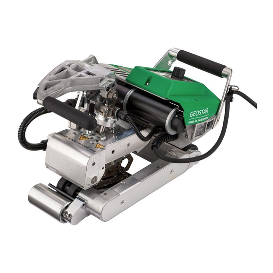
  • Page 66: Description De L'appareil

    Description de l’appareil 1. Câble d’alimentation secteur 14. Système de contact, en haut 2. Interrupteur principal 15. Système de contact, en bas 3. Panneau de commande 16. Rouleau d'entraînement/de pression du haut 4. Bras de serrage 17. Rouleau d'entraînement/de pression du bas 5.
  • Page 67: Panneau De Commande

    Panneau de commande 27. Touche « Haut » 28. Touche « Bas » 29. Touche « Marche/Arrêt » du chauff age 30. Touche « Marche/Arrêt » de l’entraî- nement 31. LED d’état 32. « e-Drive » 33. Affi chage de fonction 34. Affi chage de travail 35. Affi chage d’état « Zone 1 » 36.
  • Page 68: Description De L'unité De Commande

    État affichage LED « Chauffage » La LED de la touche « Marche/Arrêt » du chauffage (29) indique les états du chauffage. État LED (31) État Cause Chauffage Marche/Arrêt (29) LED éteinte Le chauffage est éteint. Le chauffage est allumé. La tempé- La LED clignote en vert rature est hors limites de la plage de tolérance.
  • Page 69: Description De L'écran

    Description de l’unité de commande La valeur réglée est reprise directement La fonction Appuyer sur Sélection de la position et la sélection revient sélectionnée « e-Drive » (32) marquée. automatiquement à l’af- est exécutée. fi chage des fonctions. • Modifi e la position Réglage des valeurs de dans le menu Setup.
  • Page 70 Affichage de fonction et de travail Affichage de travail (34) Symbole Signification Vitesse de l'entraînement [m/min / ft./min] Vitesse de l'entraînement bloqué [m/min / ft./min] Température de la panne chauff ante [°C/°F] Force d’assemblage [N/lbs] Fenêtre d’informations Appareils en mode veille. Après écoulement du temps de compteur, le chauff age est éteint.
  • Page 71: Aperçu De L'affichage De Travail

    Aperçu de l’affichage de travail Affichage de lancement Sélection de profil Affi chage lors du lance- Sélectionnez un profi l que ment avec version logiciel vous avez défi ni. La sélec- et type d'appareil. tion de profi l est décrite au chapitre « ...
  • Page 72 Aperçu de l’affichage de travail Veille Show Duty Info Le mode veille est activé. Hours Drive : Si le moteur est coupé, le Temps de fonctionnement chauff age éteint et si au- actuel de l'entraînement cune touche n'est activée Hours Heating : pendant le temps défi...
  • Page 73 Aperçu de l’affichage de travail Machine Setup Show Set Values Si la fonction «  Show Set Select Unit : Values  » (Affi cher valeurs Réglage de l’unité utilisée prédéfi nies) est activée, les (métrique/impériale) valeurs réelles (en grand) LCD Contrast : et les valeurs de consigne Réglage du contraste LCD (en petit) sont affi chées.
  • Page 74: Navigation Dans Le Menu

    Navigation dans le menu Disponible uniquement en « Advanced Mode »...
  • Page 75: Environnement De Travail/Sécurité

    Environnement de travail/Sécurité L'appareil ne doit être utiliser qu’à l’extérieur ou dans des locaux bien ventilés. Veiller à ne pas brûler le matériau lors du processus de soudage. Consulter la fiche technique de sécurité matériau du fabricant et suivre les indications. Avant la mise en service, contrôler le câble d'alimentation secteur (1) et la fiche ainsi que la rallonge pour repérer tout dommage électrique ou mécanique.
  • Page 76: Réglage Des Paramètres De Soudage

    Réglage des paramètres de soudage ATTENTION ! La panne chauffante a été réglée en usine pour les membranes de 2 mm. Pour le réglage, la panne chauffante (5) doit être refroidie. Risque d'écrasement en fermant le bras de serrage (4). Éteindre GEOSTAR à l'interrupteur principal (2) et le débrancher du réseau. Force d’assemblage et système de contact A.
  • Page 77 Réglage des paramètres de soudage C. Rentrer les bandes d'essai (membrane inférieure et supérieure) du matériau à souder entre les rouleaux d'en- traînement/de pression du haut et du bas (16/17) et entre les systèmes de contact du haut et du bas (14/15) et la panne chauffante (5).
  • Page 78 Réglage des paramètres de soudage E. Éteindre l'interrupteur principal (2) et débrancher GEOSTAR du réseau. À l'état serré, visser le système de contact du bas (15) avec la vis de réglage du système de contact du bas (19) en direction de la panne chauff ante (5) jusqu'à...
  • Page 79: Description De La Fonction

    Description de la fonction Système de chauffage : • La température de la panne chauff ante est réglable et réglée électroniquement entre 80 °C et 460 °C. • La température peut être réglée par pas de 5 °C. Force d'assemblage • La force d'assemblage est réglable progressivement. La force d'assemblage est transmise sur les rouleaux d'entraînement/de pression du haut et du bas (16/17) via le levier de serrage (7) et le bras de serrage (4).
  • Page 80: Réglage De Vitesse Et De Température Pendant Le Soudage

    Réglage de vitesse et de température pendant le soudage Si l'entraînement est activé, les paramètres de soudage Température et Vitesse sont réglés dans l'affichage de travail (34) comme suit : • Pendant le soudage, l'affichage de travail Vitesse (34) est verrouillé. •...
  • Page 81: Procédure De Soudage

    Procédure de soudage Avant d'utiliser la soudeuse automatique à panne chauffante, procéder à des essais de sou- dage conformément aux instructions de soudage du fabricant de matériaux et aux normes ou directives nationales. Les essais de soudage doivent être contrôlés. •...
  • Page 82: Affichage De Distance Journalière

    Affichage de distance journalière Dès que l'entraînement est en marche et que plus de 200 N de force est affi ché dans l'affichage de travail (34), la distance de soudure est enregistrée. La distance journalière peut être appelée de la manière suivante : Pas en processus de soudage •...
  • Page 83: Effacer La Distance Journalière

    Effacer la distance journalière • Dans l’affichage des fonctions (33), sélectionner le menu Réglages en tournant le bouton « e-Drive » • Appuyer brièvement sur le bouton « e-Drive » • Dans le menu « Setup », sélectionner « Show Duty Info » en tournant le bouton « e-Drive » et en appuyant brièvement sur cette commande •...
  • Page 84: Saisie De Noms Et De Mots De Passe

    Saisie de noms et de mots de passe Le mode clavier permet de défi nir des noms ou de saisir des mots de passe comportant 12 caractères au maximum. Clavier Sélection d’un caractère (37) Sélection d’un symbole (38) Vers le haut (27) Sélection verticale d’un caractère Vers le bas (28) Tourner...
  • Page 85 Définition de profils Réglage d’un nouveau profi l : • Dans l'affichage de travail (34), régler les valeurs de consigne souhaitées avec l'« e-Drive » • Dans l'affichage des fonctions (33) avec l'« e-Drive » , sélectionner le menu Réglages et confi rmer en appuyant sur le bouton « e-Drive » •...
  • Page 86: Coupure De Secteur

    Coupure de secteur État de l’appareil avant la coupure Durée coupure État de l’appareil après coupure de secteur de secteur de secteur L’appareil continue de fonctionner sans L’entraînement et le chauffage sont enclen- protection anti-redémarrage selon les ≤ 5 s chés ( processus de soudage).
  • Page 87: Changer D'étage D'engrenage

    Changer d'étage d'engrenage Étage d'engrenage lent Étage d'engrenage rapide Avec l'étage d'engrenage « rapide » (fast), la machine dispose de moins de force d'avance (couple de rotation plus petit). Avant le démontage, il faut s'assurer que la panne chauffante est refroidie et que l'appareil est éteint sur l'interrupteur principal (2) et que le câble de réseau est débranché.
  • Page 88 Changer d'étage d'engrenage D. Monter le couvercle d'engrenage (43) avec les vis à tête fraisée (42). E. Adaptation du rapport de transmission • Dans l'affichage des fonctions (33), sélectionner Réglage avec l'« e-Drive » et confi rmer ensuite & • Sélectionner ensuite « Gear Ratio Drive » (Rapport de transmission de l'entraîne- ment) en tournant le bouton « e-Drive »...
  • Page 89: Remplacement Des Rouleaux De Pression

    Remplacement des rouleaux de pression Avant le démontage, il faut s'assurer que la panne chauffante est refroidie et que l'appareil est éteint sur l'interrupteur principal (2) et que le câble de réseau est débranché. Diff érents rouleaux d'entraînement/de pression peuvent être utilisés en fonction de l'application. Démontage des rouleaux d'entraînement/ de pression du bas (17) : Séquence 1 à...
  • Page 90 Remplacement panne chauffante Avant le démontage, il faut s'assurer que la panne chauffante est refroidie et que l'appareil est éteint sur l'interrupteur principal (2) et que le câble de réseau est débranché. A. Tourner la bague du connecteur de panne chauff ante (13) dans le sens contraire des aiguilles d'une montre jusqu'à...
  • Page 91: Avertissements Et Messages D'erreur

    • Si une erreur se produit, l’appareil coupe le chauff age et l’entraînement se verrouille. • En cas de blocage de l'entraînement, éteindre l'interrupteur principal (2) et débrancher le câble d’alimenta- tion (1) du réseau électrique. Contacter le centre de service Leister. Type de...
  • Page 92: Accessoires

    Accessoires • Seuls des accessoires Leister doivent être utilisés. Formation • Leister Technologies AG et ses centres de services agréés offrent des formations et des cours de soudure. Informations sur le site www.leister.com. Entretien • Débrancher l'appareil du réseau avant d'eff ectuer des travaux de maintenance.
  • Page 96 ® © Copyright by Leister Your authorised Service Centre is: Leister Technologies AG Galileo-Strasse 10 CH-6056 Kaegiswil/Switzerland Tel. +41 41 662 74 74 +41 41 662 74 16 www.leister.com sales@leister.com...

Ce manuel est également adapté pour:

Geostar g7

Table des Matières